Transcript
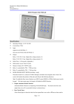
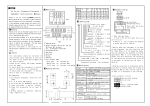
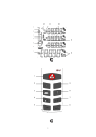
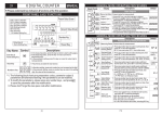
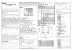
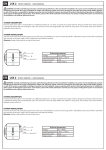
MYPIN
Intelligent Timer & Counter
User Manual
Thanks a lot for selecting
③ Parameters/timing/delay time display
④ Preset value/timing/delay time setting display
⑤ Key setting:
SET: Confirm key
Before operating this instrument, please carefully read this manual and
fully understand its contents. If any probroms, please contact our sales or
distributors whom you buy from. This manual is subject to change without
prior notice.
! Caution
Avoid interference sources . If the signal cable is too long, you’d better use shield
cable.Please don’t install the signal cable together with the power.
Avoid using this instrument in environment of strong shock or concussion.
Avoid using this instrument in environment full of corrosivity,flamable gas,
dust,strong viabration.
Storage -10℃~+70℃,avoid direct sunshine
★ Application
1,Various timing range setting
2,2 segments control output
3, High accuracy timing
4, RS485 interface, MODBUS protocol
↓ SET
Start timing setting:
<±0.1%
Termina reset <0.1S, Manual reset<2S
0.01S-9999H(4 digit)
0.01S-99999(5 digit)
Contact load
AC 250V 3A COS¢=1
Communication
RS485
Timing value setting & Display types conversion
★Timing value setting: In timing estate, press /M to shift,LED flashes,
Press
/
to set the value, SET key to confirm.Then press , time
unit lamps changes,press SET to confirm.
★Display types conversion:
N type: timing to PV value and hold the value
F type: timing to PV value and keep timing up
R type: timing to SV delay value,PV dispay remain delay time
★Manual reset:Press /M for more than 2 seconds to start or reset the
timer.
Or reset by external terminal RST
Time value
SET
Display 0
oN: timing by RST terminal/manual reset
OUT
Power-failure protection:
90-260VAC 50/60Hz Power comsump.< 5VA
Accuracy
Reset time
Timing/delay
range
Reset
oFF: timing by power on,
↓ SET
Specification
Power
key for more than 3 seconds
Timing direction: uP: increase timing
dn: decrease timing
Dimensions: 96*48*80mm
Holing size: 91+0.5 X 45+0.5mm
Warning
Do not turn on the power supply until all of the wiring is completed. Otherwise
electrical shock, fire or malfunction may result.
Do not turn on the power supply when cleaning this instrument.
Do not disassemble, repair or modify the instrument. This may cause electrical
shock, fire or malfunction.
Use this instrument in the scope of its specifications. Otherwise fire or malfunction may result.
Display estate
↓
Model MHH8-RR4E
Output & Rest modes
N type output:
Press both
/M:Shift/reset key
: Up key
: Down key
MYPIN product!
★ All the listed values are the factory settings
↓SET
No:without YES: time value protection
Communication speed: 0:9.6K Bit/S
1-3: of no use
↓SET
F type output:
Reset
Communication address:
↓SET
After output, output & display value HOLD untill input reset
Dispaly value MAX
Timing value SET
Range:000-255
Password:Range: 0-200,
LCK=000 All parameters can be changed.
Display 0
LCK=010 Parameters can be read only.
Wiring control:
OUT1 is to connect AC contactor or other equipment for
switching ON ageing equipment.
OUT2 is for seitching OFF ageing equipment.
OUT
After output, display value keep going on until till reaches Max
display value. Output HOLD until input reset
Diagram
R type output:
. Parameters Setting
Display estate
↓
AL1
①
SV
AL2
S
SET <</M
M
④
↓SET
↓SET
↓SET
①
Segments Alarm output indicate lamps
②
OUT: Single output indicate lamp
ON: output
Time units:
S: second
↓SET
7
6
5
response to S, M, H respectively
Time units selection:
OUT2
NO
4
3
2
1
Timing value SET
Delay time value
SET
Display 0
220V AC
COM NC
OUT1
OUT
After output: When timing value reaches the setted value,the realy
keeps working for setted delay time,then reset.
response to S, M, H respectively
Output type setting:
0: N type 1: F type
2: R type others: of no use
Timing cycle index setting,
Range:1~1 million
OFF: no output
M: munite
8
Time units selection:
Delay time value setting,
Range:0.01~9999
H
<<
⑤
OUT
<<
②
10 9
SET
→
↓
Timing value setting,
Range:0.01~9999
↓
PV
Reset
SET>3S
→
③
Marks
H: hour
↓SET
1