1
User’s Manual
32
RZ/T1 Group
Renesas Starter Kit Code Generator Tutorial Manual
For e2 studio
RENESAS MCU
RZ Family / RZ/T1 Series
All information contained in these materials, including products and product specifications, represents
information on the product at the time of publication and is subject to change by Renesas Electronics
Corporation without notice. Please review the latest information published by Renesas Electronics
Corporation through various means, including the Renesas Electronics Corporation website
(http://www.renesas.com).
Rev. 1.00 Mar 2015
Notice
1.
Descriptions of circuits, software and other related information in this document are provided only to illustrate the
operation of semiconductor products and application examples. You are fully responsible for the incorporation of these
circuits, software, and information in the design of your equipment. Renesas Electronics assumes no responsibility for
any losses incurred by you or third parties arising from the use of these circuits, software, or information.
2. Renesas Electronics has used reasonable care in preparing the information included in this document, but Renesas
Electronics does not warrant that such information is error free. Renesas Electronics assumes no liability whatsoever
for any damages incurred by you resulting from errors in or omissions from the information included herein.
3. Renesas Electronics does not assume any liability for infringement of patents, copyrights, or other intellectual property
rights of third parties by or arising from the use of Renesas Electronics products or technical information described in
this document. No license, express, implied or otherwise, is granted hereby under any patents, copyrights or other
intellectual property rights of Renesas Electronics or others.
4. You should not alter, modify, copy, or otherwise misappropriate any Renesas Electronics product, whether in whole or
in part. Renesas Electronics assumes no responsibility for any losses incurred by you or third parties arising from such
alteration, modification, copy or otherwise misappropriation of Renesas Electronics product.
5. Renesas Electronics products are classified according to the following two quality grades: “Standard” and “High
Quality”. The recommended applications for each Renesas Electronics product depends on the product’s quality grade,
as indicated below.
“Standard”: Computers; office equipment; communications equipment; test and measurement equipment; audio
and visual equipment; home electronic appliances; machine tools; personal electronic equipment; and industrial
robots etc.
“High Quality”: Transportation equipment (automobiles, trains, ships, etc.); traffic control systems; anti-disaster
systems; anticrime systems; and safety equipment etc.
Renesas Electronics products are neither intended nor authorized for use in products or systems that may pose a
direct threat to human life or bodily injury (artificial life support devices or systems, surgical implantations etc.), or may
cause serious property damages (nuclear reactor control systems, military equipment etc.). You must check the quality
grade of each Renesas Electronics product before using it in a particular application. You may not use any Renesas
Electronics product for any application for which it is not intended. Renesas Electronics shall not be in any way liable
for any damages or losses incurred by you or third parties arising from the use of any Renesas Electronics product for
which the product is not intended by Renesas Electronics.
6. You should use the Renesas Electronics products described in this document within the range specified by Renesas
Electronics, especially with respect to the maximum rating, operating supply voltage range, movement power voltage
range, heat radiation characteristics, installation and other product characteristics. Renesas Electronics shall have no
liability for malfunctions or damages arising out of the use of Renesas Electronics products beyond such specified
ranges.
7. Although Renesas Electronics endeavors to improve the quality and reliability of its products, semiconductor products
have specific characteristics such as the occurrence of failure at a certain rate and malfunctions under certain use
conditions. Further, Renesas Electronics products are not subject to radiation resistance design. Please be sure to
implement safety measures to guard them against the possibility of physical injury, and injury or damage caused by fire
in the event of the failure of a Renesas Electronics product, such as safety design for hardware and software including
but not limited to redundancy, fire control and malfunction prevention, appropriate treatment for aging degradation or
any other appropriate measures. Because the evaluation of microcomputer software alone is very difficult, please
evaluate the safety of the final products or systems manufactured by you.
8. Please contact a Renesas Electronics sales office for details as to environmental matters such as the environmental
compatibility of each Renesas Electronics product. Please use Renesas Electronics products in compliance with all
applicable laws and regulations that regulate the inclusion or use of controlled substances, including without limitation,
the EU RoHS Directive. Renesas Electronics assumes no liability for damages or losses occurring as a result of your
noncompliance with applicable laws and regulations.
9. Renesas Electronics products and technology may not be used for or incorporated into any products or systems whose
manufacture, use, or sale is prohibited under any applicable domestic or foreign laws or regulations. You should not
use Renesas Electronics products or technology described in this document for any purpose relating to military
applications or use by the military, including but not limited to the development of weapons of mass destruction. When
exporting the Renesas Electronics products or technology described in this document, you should comply with the
applicable export control laws and regulations and follow the procedures required by such laws and regulations.
10. It is the responsibility of the buyer or distributor of Renesas Electronics products, who distributes, disposes of, or
otherwise places the product with a third party, to notify such third party in advance of the contents and conditions set
forth in this document, Renesas Electronics assumes no responsibility for any losses incurred by you or third parties as
a result of unauthorized use of Renesas Electronics products.
11. This document may not be reproduced or duplicated in any form, in whole or in part, without prior written consent of
Renesas Electronics.
12. Please contact a Renesas Electronics sales office if you have any questions regarding the information contained in this
document or Renesas Electronics products, or if you have any other inquiries.
(Note 1) “Renesas Electronics” as used in this document means Renesas Electronics Corporation and also includes its
majority owned subsidiaries.
(Note 2) “Renesas Electronics product(s)” means any product developed or manufactured by or for Renesas Electronics.
(2012.4)
Disclaimer
By using this Renesas Starter Kit (RSK), the user accepts the following terms:
The RSK is not guaranteed to be error free, and the entire risk as to the results and performance of the RSK is
assumed by the User. The RSK is provided by Renesas on an “as is” basis without warranty of any kind whether
express or implied, including but not limited to the implied warranties of satisfactory quality, fitness for a particular
purpose, title and non-infringement of intellectual property rights with regard to the RSK. Renesas expressly
disclaims all such warranties. Renesas or its affiliates shall in no event be liable for any loss of profit, loss of data,
loss of contract, loss of business, damage to reputation or goodwill, any economic loss, any reprogramming or recall
costs (whether the foregoing losses are direct or indirect) nor shall Renesas or its affiliates be liable for any other
direct or indirect special, incidental or consequential damages arising out of or in relation to the use of this RSK, even
if Renesas or its affiliates have been advised of the possibility of such damages.
Precautions
The following precautions should be observed when operating any RSK product:
This Renesas Starter Kit is only intended for use in a laboratory environment under ambient temperature and humidity
conditions. A safe separation distance should be used between this and any sensitive equipment. Its use outside the
laboratory, classroom, study area or similar such area invalidates conformity with the protection requirements of the
Electromagnetic Compatibility Directive and could lead to prosecution.
The product generates, uses, and can radiate radio frequency energy and may cause harmful interference to radio
communications. However, there is no guarantee that interference will not occur in a particular installation. If this
equipment causes harmful interference to radio or television reception, which can be determined by turning the
equipment off or on, you are encouraged to try to correct the interference by one or more of the following measures;
·
ensure attached cables do not lie across the equipment
·
reorient the receiving antenna
·
increase the distance between the equipment and the receiver
·
connect the equipment into an outlet on a circuit different from that which the receiver is connected
·
power down the equipment when not in use
·
consult the dealer or an experienced radio/TV technician for help NOTE: It is recommended that wherever
possible shielded interface cables are used.
The product is potentially susceptible to certain EMC phenomena. To mitigate against them it is recommended that the
following measures be undertaken;
·
The user is advised that mobile phones should not be used within 10m of the product when in use.
·
The user is advised to take ESD precautions when handling the equipment.
The Renesas Starter Kit does not represent an ideal reference design for an end product and does not fulfil the
regulatory standards for an end product.
How to Use This Manual
1.
Purpose and Target Readers
This manual is designed to provide the user with an understanding of how to use Code Generator for RZ
2
together with the e studio IDE to create a working project for the RSK platform. It is intended for users
designing sample code on the RSK platform, using the many different incorporated peripheral devices.
2
The manual comprises of step-by-step instructions to generate code and import it into e studio, but does not
intend to be a complete guide to software development on the RSK platform. Further details regarding
operating the RZT1 microcontroller may be found in the Hardware Manual and within the provided sample
code.
Particular attention should be paid to the precautionary notes when using the manual. These notes occur within the body
of the text, at the end of each section, and in the Usage Notes section.
The revision history summarizes the locations of revisions and additions. It does not list all revisions. Refer to the text of
the manual for details.
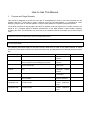
The following documents apply to the RZT1 Group. Make sure to refer to the latest versions of these
documents. The newest versions of the documents listed may be obtained from the Renesas Electronics Web
site.
Document Type
Description
Document Title
Document No.
User’s Manual
Describes the technical details of the RSK hardware.
RSK+RZT1
Manual
User’s
R20UT3242EG
Tutorial
Provides a guide to setting up RSK environment,
running sample code and debugging programs.
RSK+RZT1 Tutorial
Manual
R20UT3243EG
Quick Start Guide
Provides simple instructions to setup the RSK and
run the first sample.
RSK+RZT1
Start Guide
Quick
R20UT3244EG
Code Generator
Tutorial
Provides a guide to the standalone code generation
tool.
RSK+RZT1
Code
Generator Tutorial
Manual
R20UT3281EG
Schematics
Full detail circuit schematics of the RSK.
RSK+RZT1
Schematics
R20UT3241EG
Hardware Manual
Provides
technical
microcontroller.
RZ/T1
RZT1 Group, User’s
Manual: Hardware
R01UH0483EJ
NOR Boot Loader
Application Note
Describes operational details of the NOR Boot
Loader Program.
RZT1 NOR Boot
Loader Application
Note
R01AN2470EG
QSPI Boot Loader
Application Note
Describes operational details of the QSPI Boot
Loader Program.
RZT1 QSPI Boot
Loader Application
Note
R01AN2471EG
details
of
the
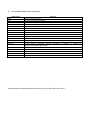
2.
List of Abbreviations and Acronyms
Abbreviation
Full Form
ADC
Analog-to-Digital Converter
API
COM
Application Programming Interface
COMmunications port referring to PC serial port
CPU
DVD
Central Processing Unit
Digital Versatile Disc
E1
GUI
Renesas On-chip Debugger
Graphical User Interface
IDE
IRQ
Integrated Development Environment
Interrupt Request line
LCD
LED
Liquid Crystal Display
Light Emitting Diode
MCU
PC
Micro-controller Unit
Personal Computer
TM
Pmod
Digilent Pmod™ Compatible connector.
Digilent-Pmod_Interface_Specification
PLL
QSPI
Phase-locked Loop
Quad Serial Peripheral Interface
RSK
SCI
Renesas Starter Kit
Serial Communications Interface
SPI
Serial Peripheral Interface
PmodTM
is
registered
All trademarks and registered trademarks are the property of their respective owners.
to
Digilent
Inc.
Table of Contents
1. Overview............................................................................................................................ 7
1.1
1.2
Purpose ...................................................................................................................................................... 7
Features ..................................................................................................................................................... 7
2. Introduction ........................................................................................................................ 8
3. Project Creation with e2 studio ........................................................................................... 9
3.1
3.2
Introduction ................................................................................................................................................ 9
Creating the Project ................................................................................................................................... 9
4. Using the Code Generator ............................................................................................... 14
4.1
4.2
4.3
Introduction .............................................................................................................................................. 14
Code Generator Tour ............................................................................................................................... 14
Code Generation ...................................................................................................................................... 16
4.3.1
Peripheral Function Configuration ................................................................................................. 16
4.3.2
Generating the Code ...................................................................................................................... 22
5. Adding Code to Generated Files ...................................................................................... 23
5.1
5.2
Excluding Files ......................................................................................................................................... 23
Adding Code to Generated Files ............................................................................................................. 24
5.2.1
r_cg_userdefine.h Code Insertion .................................................................................................. 24
5.2.2
r_cg_icu_user.c Code Insertion...................................................................................................... 24
5.2.3
r_cg_icu.h Code Insertion .............................................................................................................. 24
5.2.4
r_cg_cmt_user.c Code Insertion .................................................................................................... 24
5.2.5
r_cg_main.c Code Insertion ........................................................................................................... 25
5.3
Additional include paths ........................................................................................................................... 26
5.4
Release Build Section Map ...................................................................................................................... 27
6. External Linker File .......................................................................................................... 28
6.1
6.2
Linker File Over-ride ................................................................................................................................ 28
Building the Project .................................................................................................................................. 30
7. Executing the Project ....................................................................................................... 31
8. Usage Notes .................................................................................................................... 32
8.1
8.2
iodefine.h File ........................................................................................................................................... 32
RIIC Module ............................................................................................................................................. 32
9. Additional Information ...................................................................................................... 33
RSK+RZT1
RENESAS STARTER KIT
R20UT3281EG0100
Rev. 1.00
Mar 21, 2015
1. Overview
1.1
Purpose
2
This RSK is an evaluation tool for Renesas microcontrollers. This manual describes how to use the e studio
IDE Code Generator plug in to create a working project for the RSK platform.
1.2
Features
This RSK tutorial guides the user through creating a project to evaluate the following features:
2
·
Project creation with e studio,
·
Code Generation using the Code Generator plug in,
·
User circuitry such as switches, LEDs and a potentiometer.
The RSK board contains all the circuitry required for microcontroller operation.
R20UT3281EG0100 Rev. 1.00
Mar 21, 2015
Page 7 of 37
RSK+RZT1
2. Introduction
2. Introduction
This manual is designed to answer, in tutorial form, how to use the Code Generator plug in for the RZ family
2
together with the e studio IDE to create a working project for the RSK platform. The tutorials help explain the
following:
·
Project generation using the e studio,
·
Detailed use of the Code Generator plug in for e studio,
·
Integration with custom code,
·
Building and running the project e studio.
2
2
2
The project generator will create a tutorial project with two selectable build configurations:
·
‘HardwareDebug’ is a project built with the debugger support included. Optimisation is set to zero.
·
‘Release’ is a project with optimised compile options, producing code suitable for release in a product.
Some of the illustrative screenshots in this document will show text in the form RZxx. These are general
screenshots and are applicable across the whole RZ family. In this case, simply substitute RZxx for RZT1
These tutorials are designed to show you how to use the RSK and are not intended as a comprehensive introduction to
2
the e studio debugger, compiler toolchains or the J-Link emulator. Please refer to the relevant user manuals for more indepth information.
R20UT3281EG0100 Rev. 1.00
Mar 21, 2015
Page 8 of 37
RSK+RZT1
2
3. Project Creation with e studio
3. Project Creation with e2 studio
3.1
Introduction
In this section the user will be guided through the steps required to create a new ‘C’ project for the RZT1
microcontroller, ready to generate and add peripheral driver code using Code Generator. This project
generation step is necessary to create the MCU-specific source, project and debug files.
3.2
Creating the Project
·
Start e studio and select a suitable
location for the project workspace.
2
Start e studio and select a suitable
location for the project workspace.
·
In the Welcome page, click ‘Go to the
workbench’.
2
R20UT3281EG0100 Rev. 1.00
Mar 21, 2015
Page 9 of 37
RSK+RZT1
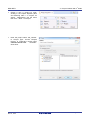
·
Create a new C project by rightclicking in the Project Explorer pane
and selecting ‘New -> C Project’ as
shown. Alternatively, use the menu
item ‘File -> New -> C Project’.
·
Enter the project name ‘CG_Tutorial’.
In ‘Project type:’ choose ‘Sample
Project’. In ‘Toolchains’ choose ‘KPIT
GNUARM-NONE-EABI
Toolchain’.
Click ‘Next’.
R20UT3281EG0100 Rev. 1.00
Mar 21, 2015
2
3. Project Creation with e studio
Page 10 of 37
2
RSK+RZT1
3. Project Creation with e studio
·
In the ‘Target Specific Settings’ dialog,
select the options as shown in the
screenshot opposite.
·
The R7S910018 MCU is found under
RZ/T -> RZ/T1 -> RZ/T1 - 320 pin ->
R7S910018.
·
Click ‘Next’.
·
Select
‘Use
Generator’.
·
Click ‘Next’.
Peripheral
R20UT3281EG0100 Rev. 1.00
Mar 21, 2015
code
Page 11 of 37
RSK+RZT1
·
In ‘Select Additional CPU Options’
leave everything at default values.
·
Click ‘Next’.
·
In the ‘Library Generator Settings’
leave everything at default values.
·
Click ‘Finish’.
R20UT3281EG0100 Rev. 1.00
Mar 21, 2015
2
3. Project Creation with e studio
Page 12 of 37
RSK+RZT1
·
2
3. Project Creation with e studio
A summary dialog will appear, click
‘OK’ to
complete
the
project
generation.
The generated sample is a fully functional sample that can be built and executed, however, for the purpose of
this tutorial, the sample’s functionality will not be tested.
Note: the sample toggles LED0 on the RSK+RZT1 board. The toggling rate changes with variations of the
potentiometer (RV1). Pressing SW3 enables/disables the LED toggling. This manual does not focus on the
functionality of the sample.
Use ‘Build Project’ from the ‘Project’ menu or the
no errors.
R20UT3281EG0100 Rev. 1.00
Mar 21, 2015
button to build the tutorial. The project will build with
Page 13 of 37
RSK+RZT1
4. Using the Code Generator
4. Using the Code Generator
4.1
Introduction
Code Generator is a GUI tool for generating template ‘C’ source code. This tool comes in two versions, either
2
as an integrated plugin in e studio or as a standalone application. The Code Generator tool distributed with
the RSK+RZT1 is the plugin version. Code Generator enables the user is to configure various MCU features
and operating parameters using intuitive GUI controls, bypassing the need, in most cases, to refer to sections
of the Hardware Manual.
2
By following the steps detailed in this tutorial, the user will generate an e studio project called CG_Tutorial. A
2
fully completed CG_Tutorial project is contained on the DVD and may be imported into e studio by following
the steps in the Quick Start Guide. This tutorial is intended as a learning exercise for users who wish to use
2
the Code Generator to generate their own custom projects for e studio.
Once the user has configured the project, the ‘Generate Code’ function is used to generate three code
modules for each specific MCU feature selected. These code modules are named ‘r_cg_xxx.h’, ‘r_cg_xxx.c’,
and ‘r_cg_xxx_user.c’, where ‘xxx’ is a three letter acronym for the relevant MCU feature, for example ‘scifa’.
Within these code modules, the user is free to add custom code to meet their specific requirement. Custom
code should be added between the following comment delimiters:
/* Start user code for adding. Do not edit comment generated here */
/* End user code. Do not edit comment generated here */
Code Generator will locate these comment delimiters, and preserve any custom code inside the delimiters on
subsequent code generation operations. Any code outside of these comment delimiters will be overwritten on
subsequent code generation sessions.
The CG_Tutorial project uses the ADC module with external trigger, Interrupt Controller Unit (ICU) and
Comapare Match Timer (CMT) and an LED (I/O Port). As a demonstration this tutorial performs the following
actions:
·
·
·
·
Configure an LED to be toggled.
Configure an A/D channel for setting the toggling period.
Configure a timer channel to generate the toggling period.
Configure a switch used to enable or disable toggling of the LED.
Following a tour of the key user interface features of Code Generator in Section 4.2, the reader is guided
through each of the peripheral function configuration dialogs in Section 4.3.1. In Section 5, the reader is
familiarised with the structure of the template code, as well as how to add custom code in the areas provided
by the Code Generator and any other changes required to be made in the project generated in Section 3.2.
4.2
Code Generator Tour
This section presents a brief tour of Code Generator. AP4 is the stand-alone version of Code Generator and
this manual is applicable to the Code Generator.
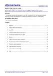
2
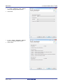
From the e studio menus, select ‘Window -> Open Perspective -> Other. In the ‘Open Perspective’ dialog
shown in Figure 4-1, select ‘Code Generator’ and click ‘OK’.
R20UT3281EG0100 Rev. 1.00
Mar 21, 2015
Page 14 of 37
RSK+RZT1
4. Using the Code Generator
Figure 4-1: Changing Perspectives
A Code Generator project file with extension ‘.cpg’ exists in the CG_Tutorial project’s .settings/CodeGenerator
directory. Code Generator also creates a folder named ‘cg_src’ in the ‘src’ folder to store generated source
and header files. The user is encouraged to add non-CodeGenerator files to the ‘src’ folder.
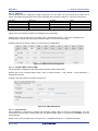
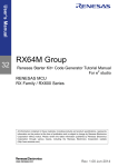
The Code Generator’s Peripheral View is displayed as illustrated in Figure 4-2.
Figure 4-2: Peripheral View
Code Generator provides GUI features for configuration of MCU sub-systems and peripherals. Once the user
has configured all required MCU sub-systems and peripherals, the user can click the ‘Generate Code’ button,
2
resulting in the creation of a number of source and header files in the e studio project’s ‘src’ folder. A few
more steps will need to be carried out before the project is fully configured and ready for use.
Navigation to the MCU peripheral configuration screens may be performed by double-clicking the required
function in the Code Generator -> Peripheral Function under the Project View pane.
It is also possible to see a preview of the code that will be generated for the current peripheral function
settings by double-clicking the required function in the Code Generator -> Code Preview on the left.
R20UT3281EG0100 Rev. 1.00
Mar 21, 2015
Page 15 of 37
RSK+RZT1
4.3
4. Using the Code Generator
Code Generation
In the following sections, the reader is guided through the steps to configure the MCU peripherals required.
Note: Configuration options that are not shown should be left with the default settings.
4.3.1
Peripheral Function Configuration
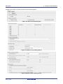
4.3.1.1 Clock Generator
Figure 4-3 shows a screenshot of Code Generator with the Clock Generator function open.
In this tutorial we are using the 25 MHz crystal resonator for the main clock source with the PLL circuit used as
a multiplier. Some peripherals can be configured to use the main clock or PLL circuitry sources to generate
their clock.
Double click on the ‘Clock Generation Circuit’ entry in Code Generator -> Peripheral Functions list in the
Project Tree.
Configure the Clock Generation Circuit options under the ‘Clock Settings’ tab as shown in Figure 4-3.
A block diagram of the Clock Generation Circuit is provided under ‘Block Diagram’ tab, shown on the next
page. This helps to see the different clock configurations available for the system and peripheral clocks.
R20UT3281EG0100 Rev. 1.00
Mar 21, 2015
Page 16 of 37
RSK+RZT1
4. Using the Code Generator
Figure 4-3: Clock setting tab
R20UT3281EG0100 Rev. 1.00
Mar 21, 2015
Page 17 of 37
RSK+RZT1
4. Using the Code Generator
4.3.1.2 I/O Ports
This peripheral will be configured to assign output pins for user LEDs. The CG_Tutorial only makes use of
LED0. User LED connectivity port pins on the schematic are as shown in Table 4-1: I/O Ports Connectivity.
Function
LED0
LED1
LED2
LED3
MCU Pin
A5
E3
K16
J18
I/O Port
PF7
P56
P77
PA0
Table 4-1: I/O Ports Connectivity
Note
Not used
Not used
Not used
Please refer to the RSK schematic for full details of the connectivity.
Double click on the ’I/O Ports’ entry in Project Tree -> Peripheral Functions -> I/O Ports. Expand the list.
Configuration is required for the port pins listed in Table 4-1: I/O Ports Connectivity.
Configure the port as shown in Figure 4-4: LED Port Pin Configuration.
Figure 4-4: LED Port Pin Configuration
4.3.1.3 Compare Match Timer (CMT)
This peripheral is configured to generate regular intervals used to flash LED0.
Double click on the ‘Compare Match Timer’ entry in Project Explorer -> CG_Tutorial -> Code Generator ->
Peripheral Functions.
Configure the CMT channel as shown in Figure 4-5.
Figure 4-5: CMT Setting Tab
4.3.1.4 A/D Converter
This peripheral is configured to sample the analogue output value of the RV1 potentiometer. The A/D
Converter is set to perform a sample when the user presses SW3, which is connected to the AN007 pin of the
microcontroller.
Double click on the ‘S12AD0’ entry in Project Tree -> Peripheral Functions -> 12-Bit A/D Converter.
R20UT3281EG0100 Rev. 1.00
Mar 21, 2015
Page 18 of 37
RSK+RZT1
4. Using the Code Generator
Configure the ‘Setting 1’ sub-tab as shown in the following figures:
Figure 4-6: A/D Converter Setting tab
Figure 4-7: A/D Converter Setting tab (2)
Figure 4-8 A/D Converter Setting tab (3)
R20UT3281EG0100 Rev. 1.00
Mar 21, 2015
Page 19 of 37
RSK+RZT1
4. Using the Code Generator
Figure 4-9 A/D Converter Setting tab (4)
Figure 4-10: A/D Converter Setting tab (5)
4.3.1.5 Interrupt Controller Unit (ICU)
This peripheral is used to configure external interrupts input pins connected to user switches. The CG_Tutorial
only makes use of switch SW3. User switch connectivity on the schematic are shown in Table 4-2: ICU
Connectivity
Function
NMI
IRQ5
IRQ12
MCU Pin
H3
W3
W15
I/O Port
P35
PN5
P44
Table 4-2: ICU Connectivity
Note
Not used.
Not used.
SW3
Please refer to the RSK schematic for full details of the connectivity.
Double click on the ‘Interrupt Controller’ entry under the Project Tree -> Peripheral Functions list.
This is to configure switch SW3 to trigger IRQ12 interrupts.
Figure 4-11: ICU Setting tab
4.3.1.6 Multi-Function Pin Controller (MPC)
This peripheral is used to select and map port/peripheral functionalities of the MCU pins. By default, mapping
of functionalities to pins is done during peripheral configuration as shown in the setup of the I/O Ports, A/D and
ICU modules. The Multi-Function Controller is used to re-assign the default functionalities mapping if required.
Double click on the ‘Device List View’ entry under the Project Tree -> Pin View.
Please ensure to verify the port pin functions for each configured peripheral by viewing the ‘Pin Number’ and
‘Pin Function’ tabs as shown in Figure 4-12: Pin Number Device List View tab and Figure 4-13: Pin Function
Device List View tab
R20UT3281EG0100 Rev. 1.00
Mar 21, 2015
Page 20 of 37
RSK+RZT1
4. Using the Code Generator
Figure 4-12: Pin Number Device List View tab
Figure 4-13: Pin Function Device List View tab
Figure 4-13 shows IRQ12 (Pin Name) function assigned to MCU pin number V4 but on the RSK+RZT1
schematic, V4 is connected to I/O port pin P44. The IRQ12 function needs to be re-assigned to P44 (MCU pin
number W15).
To assign/re-assign a pin, click on the pin to reveal a drop-down menu button. Click on the button to reveal a
list of available pins, then select W15 as shown in Figure 4-14.
R20UT3281EG0100 Rev. 1.00
Mar 21, 2015
Page 21 of 37
RSK+RZT1
4. Using the Code Generator
Figure 4-14: Pin Function Assignment/Re-assignement
The MPC assigns pins in the order in which the peripherals were configured. Once a pin has been assigned to
a function, configuring another peripheral that uses the same function will result in the assignment of that
function to an alternate pin. In addition, the MPC does not automatically map functions to pins based on
the connectivity on the RSK+RZT1. This is why it is important to verify the pin functions in the Device List
View.
A pin name will be shown in red if configuration clashes exist.
A remark will be shown on the Pin Remark column of the Device List View if a pin function is assigned without
configuring the peripheral that uses the function.
4.3.2
Generating the Code
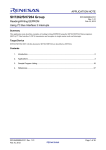
Peripheral function configuration is now complete. Click ‘Generate Code’ button located at the top right of the
Peripheral Function tab. The Output pane should report ‘The operation of generating file was successful’, as
shown Figure 4-15 below.
Figure 4-15: Code Generator’s Output pane
R20UT3281EG0100 Rev. 1.00
Mar 21, 2015
Page 22 of 37
RSK+RZT1
5. Adding Code to Generated Files
5. Adding Code to Generated Files
At this stage of a typical project development the user would expand on the generated code to create the
application required.
When inserting code in Code Generator created files, it must be placed in the areas delimited by comments as
follows:
/* Start user code for _xxxxx_. Do not edit comment generated here */
/* End user code. Do not edit comment generated here */
Where _xxxx_ depends on the particular area of code, i.e. ‘function’ for insertion of user functions and
prototypes, ‘global’ for insertion of user global variable declarations, or ‘include’ for insertion of pre-processor
include directives. User code inserted inside these comment delimiters is protected from being overwritten by
Code Generator, if the user regenerates the Code Generator code.
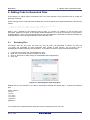
5.1
Excluding Files
All sample code can only have one main file. The init_main.c file generated in Section 3.2 and the
r_cg_main.c file generated by Code Generator both include a main function. The init_main.c file is
automatically excluded following code generation. To exclude a file from the project following these steps:
1.
2.
3.
4.
Locate the source file in the ‘Project Explorer’ view.
Right click on the file and select ‘Exclude from build…’.
Click on ‘Select All’ to make change on all available build configurations.
Click ‘OK’.
Figure 5-1: Excluding files from the project
Multiple files can be excluded in on step by selecting the desired files during step 1. Exclude the following
files:
loader_param.c
r_ecm.c
r_ecm.h
r_icu_init.c
r_icu_init.h
r_system.h
typdefine.h
To re-include a file, repeat the above steps and click on ‘Deselect All’ then click ‘OK’.
R20UT3281EG0100 Rev. 1.00
Mar 21, 2015
Page 23 of 37
RSK+RZT1
5.2
5. Adding Code to Generated Files
Adding Code to Generated Files
This section covers inserting code in to the newly created Code Generator files.
Each subsection is a Code Generator generated source file that needs to be opened by double clicking on the
2
file name in e studio’s Project Tree window under the ‘src’ folder.
The code from each section should be copied from this document and pasted in to the relevant file at the
location indicated.
5.2.1
r_cg_userdefine.h Code Insertion
2
Open this file by double clicking on the file name in e studio’s Project Tree window.
Insert the following at the end of the file between the user code delimiter comments as shown below.
/* Start user code for function. Do not edit comment generated here */
#define LED0
(PORTF.PODR.BIT.B7)
/* End user code. Do not edit comment generated here */
5.2.2
r_cg_icu_user.c Code Insertion
2
Open this file by double clicking on the file name in e studio’s Project Tree window.
Insert the followings between the specific user code insertion delimiter comments as shown below.
/* Start user code for global. Do not edit comment generated here */
volatile uint8_t g_switch_press = 0;
/* End user code. Do not edit comment generated here */
/* Start user code. Do not edit comment generated here */
/* Invert the flag */
g_switch_press = (~g_switch_press);
/* End user code. Do not edit comment generated here */
5.2.3
r_cg_icu.h Code Insertion
2
Open this file by double clicking on the file name in e studio’s Project Tree window.
Insert the following at the end of the file between the user code delimiter comments as shown below.
/* Start user code for function. Do not edit comment generated here */
extern volatile uint8_t g_switch_press;
/* End user code. Do not edit comment generated here */
5.2.4
r_cg_cmt_user.c Code Insertion
2
Open this file by double clicking on the file name in e studio’s Project Tree window.
Insert the following between the user code delimiter comments as shown below in the file section designated
Global variables and functions:
/* Start user code for include. Do not edit comment generated here */
#include "r_cg_icu.h"
#include "r_cg_cmt.h"
#include "r_cg_s12ad.h"
/* End user code. Do not edit comment generated here */
R20UT3281EG0100 Rev. 1.00
Mar 21, 2015
Page 24 of 37
RSK+RZT1
5. Adding Code to Generated Files
/* Start user code for global. Do not edit comment generated here */
/* Function prototype for scaling a value */
static uint32_t scale_value (const uint32_t value, const uint32_t in_max, const uint32_t out_max);
/* End user code. Do not edit comment generated here */
Insert the following in to the function void r_cmt_cmi1_interrupt(void)
/* Start user code. Do not edit comment generated here */
/* Update the period based on the flag set in the switch handler interrupt */
if (0 == g_switch_press)
{
/* scale the ADC value. ADC range: 0-4095, CMT range: 0 - 65478 */
CMT1.CMCOR = scale_value ((uint32_t)(S12ADC0.ADDR7), 4095, 65478);
}
else
{
/* Do not update the CMT period */
}
LED0 = (~LED0);
/* End user code. Do not edit comment generated here */
Insert the following between the user code delimiter comments at the end of the file:
/* Start user code for adding. Do not edit comment generated here */
/******************************************************************************************
* Function Name: scale_value
* Description : This function is CMI1 interrupt service routine.
*
The formula used
*
output = 1 + (value - 0) * (out_max - 0) / (in_max - 0)
*
*
Note - The actual and desired ranges' minimum value is assumed to be 0.
* Arguments
: uint32_t value
- value to scale
*
uint32_t in_max - maximum range of value to scale
*
uint32_t out_max - maximum range of desired scale
* Return Value : None
******************************************************************************************/
static uint32_t scale_value (const uint32_t value, const uint32_t in_max, const uint32_t out_max)
{
uint32_t output;
output = (out_max - 0) / (in_max - 0);
output = (value - 0) * output;
output = (1 + output);
}
return output;
/******************************************************************************************
* End of function scale_value
******************************************************************************************/
/* End user code. Do not edit comment generated here */
5.2.5
r_cg_main.c Code Insertion
Insert the following in to the function void main (void).
/* Start user code. Do not edit comment generated here */
/* The rest of the code is executed in interrupt handlers */
while (1U)
{
asm("nop");
}
/* End user code. Do not edit comment generated here */
R20UT3281EG0100 Rev. 1.00
Mar 21, 2015
Page 25 of 37
RSK+RZT1
5. Adding Code to Generated Files
Insert the following in to the function void R_MAIN_UserInit (void):
/* Start user code. Do not edit comment generated here */
uint32_t delay = 0x3FFFF;
/* Clear the switches' interrupt flags before enabling the interrupts */
VIC.PIC0.LONG = 0x00000200UL;
VIC.PIC0.LONG = 0x00010000UL;
/* Enable the switch interrupts */
R_ICU_IRQ12_Start();
/* Enabling interrupts can cause generation of an interrupt which should
be ignored. Allow some delay to catch the interrupt should it occur. */
while ((0 == g_switch_press) && (delay--))
{
asm("nop");
}
/* Ensure the switch pressed flag is cleared to enable timer period updates */
g_switch_press = 0;
/* Enable continuous A/D conversions */
R_S12AD0_Start();
/* Enable the timer's count */
R_CMT1_Start();
/* End user code. Do not edit comment generated here */
5.3
Additional include paths
Before the project can be built the compiler needs some additional include paths added. Select the
button in the toolbar to open the project settings.
CG_Tutorial project in the Project Explorer pane. Use the
Navigate to ‘C/C++ Build -> Settings ->Compiler -> Source and click the
Figure 5-2.
button as shown in below in
Figure 5-2: Adding additional search paths
R20UT3281EG0100 Rev. 1.00
Mar 21, 2015
Page 26 of 37
RSK+RZT1
5. Adding Code to Generated Files
In the ‘Add directory path’ dialog, click the ‘Workspace’ button and in the ‘Folder selection’ dialog browse to the
2
‘CG_Tutorial/src’ folder and click ‘OK’. e studio formats the path as shown in Figure 5-3 below.
Figure 5-3 Adding workspace search path
Repeat the above steps to add the workspace search paths and press OK to exit the Properties dialog.
2
button. e studio will build the project with no
Select ‘Build Project’ from the ‘Project’ menu, or use the
errors. The project may now be run using the debugger as described in §7.
5.4
Release Build Section Map
Code Generator makes changes to Linker Section addresses while generating code. These changes are only
performed on the build configuration currently selected.
The steps followed above will create a working ‘HardwareDebug’ build configuration. Follow the steps below to
create a working ‘Release’ build configuration. For details of the differences in these build configurations
please see Section 2.
Select the ‘Release’ Build configuration by clicking:
Project > Build Configurations > Set Active > Release (Release – No Debug).
In the Project Explorer tree, right click the entry ‘Code Generator’ and select ‘Generate Code’. This will run an
update for the generated code and make the required changes to Linker Section addresses.
Open the Release configuration from:
Debug Configurations > Renesas GDB Hardware Debugging . CG_Tutorial Release
Select the ‘Startup’ tab. Ensure the ‘Set breakpoint at:’ option is unticked.
Note:
Section 6 will need to be done for both
R20UT3281EG0100 Rev. 1.00
Mar 21, 2015
Page 27 of 37
RSK+RZT1
6 External Linker File
6. External Linker File
2
e studio allows specifying a different linker file to be used by the linker. The default linker map declaration can
be found in:
Project properties > C/C++ Build > Settings > Linker > Sections
The CG_Tutorial code does not make use of the default linker mapping declaration. The loader_init.asm file
includes variables declared in the default linker map. These variables are used for storing specific addresses
in the linker file. Open the loader_init.asm and change #if 1 to #if 0
6.1
Linker File Over-ride
The following steps are used to create a new linker file, define the linker sections of the RZ/T1 device and set
the GNU Linker to use the file created.
·
·
·
·
·
·
Create a new file in the project
Right click on the ‘src’ source folder.
Select New > File
Specify the name as: linker_file.ld
Open the file by double-clicking on it.
Copy and paste the following text:
/***************************************Start copying after this line******************************************/
OUTPUT_FORMAT("elf32-littlearm", "elf32-bigarm", "elf32-littlearm")
OUTPUT_ARCH(arm)
ENTRY(_PowerON_Reset)
MEMORY
{
/* Internal RAM address range H'2000_0000 to H'2001_FFFF is configured as data retention RAM */
/* Write access to this address range has to be enabled by writing to registers SYSCR1 and SYSCR2 */
ATCM
(rwx) : ORIGIN = 0x00000000, LENGTH = 0x00080000 /* (512KB) H'00000000 to H'0007FFFF */
BTCM
(rwx) : ORIGIN = 0x00800000, LENGTH = 0x00800000 /* (32KB) H'00800000 to H'00807FFF */
BUFFER_RAM (rwx) : ORIGIN = 0x08000000, LENGTH = 0x10000000 /* (128MB) H'08000000 to H'10000000 */
DATA_RAM (rwx) : ORIGIN = 0x20000000, LENGTH = 0x00080000 /* (512KB) H'20000000 to H'2007FFFF */
/* Mapped memory type */
SPI_ROM (rw) : ORIGIN = 0x30000000, LENGTH = 0x04000000
CS0_ROM (rw) : ORIGIN = 0x40000000, LENGTH = 0x04000000
CS1_ROM (rw) : ORIGIN = 0x44000000, LENGTH = 0x04000000
SDRAM0_EXT (rw) : ORIGIN = 0x48000000, LENGTH = 0x04000000
SDRAM1_EXT (rw) : ORIGIN = 0x4C000000, LENGTH = 0x04000000
}
SYS_STACK_SIZE
SVC_STACK_SIZE
IRQ_STACK_SIZE
FIQ_STACK_SIZE
UND_STACK_SIZE
ABT_STACK_SIZE
HEAP_STACK_SIZE
= 0x200;
= 0x200;
= 0x100;
= 0x100;
= 0x100;
= 0x100;
= 0x1000;
/* Application stack size
/* SVC mode stack
/* IRQ mode stack
/* FRQ mode stack
/* SVC mode stack
/* ABT mode stack
/* Heap stack size
*/
*/
*/
*/
*/
*/
*/
ATCM_BASE
= 0x00000000; /* User application located here
*/
BTCM_BASE
= 0x00800000; /* BTCM base address
*/
USER_EXEC_BASE
= 0x00000000; /* Application loads and runs from here */
USER_RAM
= 0x20000000; /* Application's RAM base
*/
STACK_BASE
= 0x00807800; /* Stacks located in BTCM
*/
SECTIONS
{
.loader_text USER_EXEC_BASE :
{
reset_start = .;
*(.loader_text);
. = ALIGN(0x4);
reset_end = .;
} > ATCM
R20UT3281EG0100 Rev. 1.00
Mar 21, 2015
Page 28 of 37
RSK+RZT1
6 External Linker File
.text :
{
text_start = .;
*(.text)
*(.text.startup)
text_end = .;
} > ATCM
.rodata :
{
rodata_start = .;
_start_data_ROM = .;
*(.rodata)
*(.rodata.*)
. = ALIGN(0x8);
*(.data)
*(.data.*)
_end_data_ROM = .;
*(.got.plt)
*(.got)
. = ALIGN(0x8);
rodata_end = .;
PROVIDE(end = .);
} > ATCM
_ram_data_size = (_end_data_ROM - _start_data_ROM);
.data USER_RAM :
{
_start_data_RAM = .;
data_start = .;
start_data_RAM = .;
. += _ram_data_size;
data_end = .;
}
.bss data_end :
{
bss_start = .;
PROVIDE(__bss_start__ = .);
*(.bss)
*(.bss.**)
*(COMMON)
. = ALIGN(0x4);
PROVIDE(__bss_end__ = .);
ebss_end = .;
_end = .;
PROVIDE(end = .);
}
.heap :
{
heap_start = .;
. = ALIGN(0x8);
*(.heap_stack)
. += HEAP_STACK_SIZE;
heap_end = .;
} > ATCM
.sys_stack 0x807800 : AT (0x807800)
{
sys_stack_start = .;
. = ALIGN(0x8);
*(.sys_stack)
. += SYS_STACK_SIZE;
sys_stack_end = .;
_sys_stack = .;
} > BTCM
.svc_stack 0x807A00 : AT (0x807A00)
{
svc_stack_start = .;
. = ALIGN(0x8);
*(.svc_stack)
. += SVC_STACK_SIZE;
svc_stack_end = .;
R20UT3281EG0100 Rev. 1.00
Mar 21, 2015
Page 29 of 37
RSK+RZT1
6 External Linker File
_svc_stack = .;
} > BTCM
.irq_stack 0x807C00 : AT (0x807C00)
{
irq_stack_start = .;
. = ALIGN(0x8);
*(.irq_stack)
. += IRQ_STACK_SIZE;
irq_stack_end = .;
_irq_stack = .;
} > BTCM
.fiq_stack 0x807D00 : AT (0x807D00)
{
fiq_stack_start = .;
. = ALIGN(0x8);
*(.fiq_stack)
. += FIQ_STACK_SIZE;
fiq_stack_end = .;
_fiq_stack = .;
} > BTCM
.und_stack 0x807E00 : AT (0x807E00)
{
und_stack_start = .;
. = ALIGN(0x8);
*(.und_stack)
. += UND_STACK_SIZE;
und_stack_end = .;
_und_stack = .;
} > BTCM
.abt_stack 0x807F00 : AT (0x807F00)
{
abt_stack_start = .;
. = ALIGN(0x8);
*(.abt_stack)
. += ABT_STACK_SIZE;
abt_stack_end = .;
_abt_stack = .;
} > BTCM
}
/*****************************************Stop copying on the above line******************************************/
Click File > Save
·
·
·
·
·
·
·
Open Project properties > C/C++ Build > Settings > Linker Other
Change the ‘Command file overide’ option to ‘External Linker script(-T)’.
Add the following to the ‘File’ entry (including the speech marks):
"${workspace_loc:/${ProjName}/src/linker_file.ld}"
Click ‘Apply’.
Navigate to Project properties > C/C++ Build > Settings > Linker Other > Miscellaneous
Ensure to untick the ‘Enable garbage collection of unused input sections(-gc-sections) if it is ticked.
Click ‘OK’.
The above 7 steps needs to be done for the HardwareDebug and Release configurations.
6.2
Building the Project
The project template created by Code Generator can now be built. In the Project Explorer pane expand the
‘src’ folder.
Use ‘Build Project’ from the ‘Project’ menu or the
will build with no errors.
R20UT3281EG0100 Rev. 1.00
Mar 21, 2015
button to build the CG_Tutorial project. The project
Page 30 of 37
RSK+RZT1
7 Executing the Project
7. Executing the Project
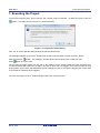
In the Project Explorer pane, ensure that the ‘CG_Tutorial’ project is selected. To debug the project, click the
button. The dialog shown in Figure 7-1 will be displayed.
Figure 7-1: Perspective Switch Dialog
Click ‘OK’ to confirm that the debug window perspective will be used.
2
The debugger will start up and the e studio will show the Code Generator function ‘PowerOn_Reset’.
button. The debugger will stop again at the beginning of the main() function.
Click the ‘Resume’
again to run the code.
Press
The program will toggle LED0 at a rate set by the position of RV1. Slowly rotate RV1 fully clockwise then
counter-clockwise and observe the change in the rate at which the LED toggles. Press SW3 to keep the rate
at the position of RV1 when the SW3 was pressed. Rotating RV1 will not change the toggling rate. Press SW3
to re-enable the variations to the toggling.
2
For more information on the e studio debugger refer to the Tutorial manual.
R20UT3281EG0100 Rev. 1.00
Mar 21, 2015
Page 31 of 37
RSK+RZT1
8. Usage Notes
8. Usage Notes
8.1
iodefine.h File
Location of the iodefine.h file.
By default, the r_cg_macrodriver.h header file which includes the iodefine.h file expects the iodefine.h file to
be located in the ‘src’ folder.
8.2
RIIC Module
The RIIC peripheral contains an error in one of its interrupt handler functions. In the r_cg_riic_user.c file, in the
function void r_riic0_error_interrupt(void), replace the existing else if condition and the encapsulated lines of
code with the following:
else if (_IIC_MASTER_RECEIVE == g_riic0_mode_flag)
{
if ((_IIC_MASTER_SENDS_ADR_7_R == g_riic0_state) || (_IIC_MASTER_SENDS_ADR_10A_W == g_riic0_state))
{
RIIC0.ICSR2.BIT.START = 0U;
RIIC0.ICIER.BIT.STIE = 0U;
RIIC0.ICIER.BIT.SPIE = 1U; /* Enable stop condition detection to prepare for the next receive */
/* Enable the TXI0 interrupt */
VIC.IEN3.LONG |= 0x08000000UL;
/* Enable the RXI0 interrupt */
VIC.IEN3.LONG |= 0x04000000UL;
}
else if (_IIC_MASTER_RECEIVES_RESTART == g_riic0_state)
{
RIIC0.ICSR2.BIT.START = 0U;
RIIC0.ICIER.BIT.STIE = 0U;
g_riic0_state = _IIC_MASTER_SENDS_ADR_10A_R;
}
else if (_IIC_MASTER_RECEIVES_STOP == g_riic0_state)
{
RIIC0.ICMR3.BIT.RDRFS = 0U;
RIIC0.ICMR3.BIT.ACKWP = 1U;
RIIC0.ICMR3.BIT.ACKBT = 0U;
RIIC0.ICSR2.BIT.NACKF = 0U;
RIIC0.ICSR2.BIT.STOP = 0U;
RIIC0.ICIER.BIT.SPIE = 0U;
RIIC0.ICIER.BIT.STIE = 1U; /* Enable start condition detection to prepare for the next receive */
/* Clear TXI0 interrupt flag */
VIC.PIC3.LONG = 0x08000000UL;
/* Disable TXI0 interrupt */
VIC.IEC3.LONG = 0x08000000UL;
/* Clear RXI0 interrupt flag */
VIC.PIC3.LONG = 0x04000000UL;
/* Disable RXI0 interrupt */
VIC.IEC3.LONG = 0x04000000UL;
}
}
r_riic0_callback_receiveend();
R20UT3281EG0100 Rev. 1.00
Mar 21, 2015
Page 32 of 37
RSK+RZT1
9.
Additional Information
9. Additional Information
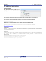
Technical Support
2
For details on how to use e studio, refer to
2
the help file by opening e studio, then
selecting Help > Help Contents from the
menu bar.
For information about the RZ/T1 group microcontroller refer to the RZ/T1 Group Hardware Manual.
For information about the RZ assembly language, refer to the RZ Series Software Manual.
Technical Contact Details
Please refer to the contact details listed in section 11 of the “Quick Start Guide”
General information on Renesas microcontrollers can be found on the Renesas website at:
http://www.renesas.com/
Trademarks
All brand or product names used in this manual are trademarks or registered trademarks of their respective
companies or organisations.
Copyright
This document may be, wholly or partially, subject to change without notice. All rights reserved. Duplication of
this document, either in whole or part is prohibited without the written permission of Renesas Electronics
Europe Limited.
© 2015 Renesas Electronics Europe Limited. All rights reserved.
© 2015 Renesas Electronics Corporation. All rights reserved.
© 2015 Renesas Solutions Corp. All rights reserved.
R20UT3281EG0100 Rev. 1.00
Mar 21, 2015
Page 33 of 37
REVISION HISTORY
Rev.
RSK RZT1 Code Generator Tutorial Manual (e2 studio)
Date
Description
Page
1.00
Mar 21, 2015
¾
Summary
First Edition issued
Renesas Starter Kit Manual: Code Generator Tutorial Manual
Publication Date:
Rev. 1.00
Mar 21, 2015
Published by:
Renesas Electronics Corporation
http://www.renesas.com
SALES OFFICES
Refer to "http://www.renesas.com/" for the latest and detailed information.
Renesas Electronics America Inc.
2801 Scott Boulevard Santa Clara, CA 95050-2549, U.S.A.
Tel: +1-408-588-6000, Fax: +1-408-588-6130
Renesas Electronics Canada Limited
9251 Yonge Street, Suite 8309 Richmond Hill, Ontario Canada L4C 9T3
Tel: +1-905-237-2004
Renesas Electronics Europe Limited
Dukes Meadow, Millboard Road, Bourne End, Buckinghamshire, SL8 5FH, U.K
Tel: +44-1628-585-100, Fax: +44-1628-585-900
Renesas Electronics Europe GmbH
Arcadiastrasse 10, 40472 Düsseldorf, Germany
Tel: +49-211-6503-0, Fax: +49-211-6503-1327
Renesas Electronics (China) Co., Ltd.
Room 1709, Quantum Plaza, No.27 ZhiChunLu Haidian District, Beijing 100191, P.R.China
Tel: +86-10-8235-1155, Fax: +86-10-8235-7679
Renesas Electronics (Shanghai) Co., Ltd.
Unit 301, Tower A, Central Towers, 555 Langao Road, Putuo District, Shanghai, P. R. China 200333
Tel: +86-21-2226-0888, Fax: +86-21-2226-0999
Renesas Electronics Hong Kong Limited
Unit 1601-1611, 16/F., Tower 2, Grand Century Place, 193 Prince Edward Road West, Mongkok, Kowloon, Hong Kong
Tel: +852-2265-6688, Fax: +852 2886-9022
Renesas Electronics Taiwan Co., Ltd.
13F, No. 363, Fu Shing North Road, Taipei 10543, Taiwan
Tel: +886-2-8175-9600, Fax: +886 2-8175-9670
Renesas Electronics Singapore Pte. Ltd.
80 Bendemeer Road, Unit #06-02 Hyflux Innovation Centre, Singapore 339949
Tel: +65-6213-0200, Fax: +65-6213-0300
Renesas Electronics Malaysia Sdn.Bhd.
Unit 1207, Block B, Menara Amcorp, Amcorp Trade Centre, No. 18, Jln Persiaran Barat, 46050 Petaling Jaya, Selangor Darul Ehsan, Malaysia
Tel: +60-3-7955-9390, Fax: +60-3-7955-9510
Renesas Electronics India Pvt. Ltd.
No.777C, 100 Feet Road, HALII Stage, Indiranagar, Bangalore, India
Tel: +91-80-67208700, Fax: +91-80-67208777
Renesas Electronics Korea Co., Ltd.
12F., 234 Teheran-ro, Gangnam-Gu, Seoul, 135-080, Korea
Tel: +82-2-558-3737, Fax: +82-2-558-5141
© 2015 Renesas Electronics Corporation. All rights reserved.
Colophon 4.0
RZT1 Group
R20UT3281EG0100