1
ISSN 0280-5316
ISRN LUTFD2/TFRT--5737--SE
Memory Protection in a
Real-Time Operating System
Rune Prytz Anderson
Per Skarin
Department of Automatic Control
Lund Institute of Technology
November 2004
Department of Automatic Control
Lund Institute of Technology
Box 118
SE-221 00 Lund Sweden
Document name
MASTER THESIS
Date of issue
November 2004
Document Number
ISRNLUTFD2/TFRT--5737--SE
Author(s)
Supervisor
Rune Prytz Anderson and Per Skarin
Karl-Erik Årzén at LTH in Lund.
Peter Hansson and Fredrik Latz at Volvo Technology in
Gothenburg.
Sponsoring organization
Title and subtitle
Memory Protection in a Real-Time Operating System (Minnesskydd i ett realtidsoperativsystem).
Abstract
During the last years the number of Electrical Control Units (ECU) in vehicles have increased rapidly with the
effect of increasing costs. To meet this trend and reduce costs, applications have to be centralized into more
powerful ECUs. This gives rise to new problems such as data and temporal integrity. The thesis gives an
introduction to these new problems and a solution based on static time-triggered scheduling combined with
memory protection. Memory protection mechanisms and hardware are evaluated, resulting in the
recommendation of a platform. The thesis also propose modification and extensions to a real-time operating
system used today within the Volvo Group. The work has been conducted at Volvo Technology (VTEC) in
Gothenburg. VTEC is a combined research and consulting company within the Volvo Group
Keywords
Classification system and/or index terms (if any)
Supplementary bibliographical information
ISSN and key title
ISBN
0280-5316
Language
Number of pages
English
79
Recipient’s notes
Security classification
The report may be ordered from the Department of Automatic Control or borrowed through:University Library, Box 3, SE-221 00 Lund, Sweden Fax +46 46
222 42 43
Contents
Acknowledgment . . . . . . . . . . . . . . . . . . . . . . . . . . . . . . . .
5
1.
Introduction . . . . .
1.1 Background . . .
1.2 Method . . . . .
1.3 Course of action
1.4 Result . . . . . .
.
.
.
.
.
.
.
.
.
.
.
.
.
.
.
.
.
.
.
.
.
.
.
.
.
.
.
.
.
.
.
.
.
.
.
.
.
.
.
.
.
.
.
.
.
.
.
.
.
.
.
.
.
.
.
.
.
.
.
.
.
.
.
.
.
.
.
.
.
.
.
.
.
.
.
.
.
.
.
.
.
.
.
.
.
.
.
.
.
.
.
.
.
.
.
.
.
.
.
.
.
.
.
.
.
.
.
.
.
.
.
.
.
.
.
.
.
.
.
.
6
6
6
6
7
2.
Objectives . . . . . . . . . .
2.1 Requirements . . . . . .
2.2 Desired features . . . .
2.3 Assignments . . . . . .
2.4 The software component
.
.
.
.
.
.
.
.
.
.
.
.
.
.
.
.
.
.
.
.
.
.
.
.
.
.
.
.
.
.
.
.
.
.
.
.
.
.
.
.
.
.
.
.
.
.
.
.
.
.
.
.
.
.
.
.
.
.
.
.
.
.
.
.
.
.
.
.
.
.
.
.
.
.
.
.
.
.
.
.
.
.
.
.
.
.
.
.
.
.
.
.
.
.
.
.
.
.
.
.
.
.
.
.
.
.
.
.
.
.
.
.
.
.
.
8
8
8
9
9
3.
Time-triggered scheduling
3.1 Introduction . . . . . .
3.2 Time-triggered tasks .
3.3 Scheduling . . . . . .
3.4 Resource allocation . .
3.5 Synchronization . . .
3.6 Idle time . . . . . . .
.
.
.
.
.
.
.
.
.
.
.
.
.
.
.
.
.
.
.
.
.
.
.
.
.
.
.
.
.
.
.
.
.
.
.
.
.
.
.
.
.
.
.
.
.
.
.
.
.
.
.
.
.
.
.
.
.
.
.
.
.
.
.
.
.
.
.
.
.
.
.
.
.
.
.
.
.
.
.
.
.
.
.
.
.
.
.
.
.
.
.
.
.
.
.
.
.
.
.
.
.
.
.
.
.
.
.
.
.
.
.
.
.
.
.
.
.
.
.
.
.
.
.
.
.
.
.
.
.
.
.
.
.
.
.
.
.
.
.
.
.
.
.
.
.
.
.
.
.
.
.
.
.
.
.
.
.
.
.
.
.
12
12
12
14
15
15
16
4.
Memory management . . . . . . . . . . . .
4.1 Introduction . . . . . . . . . . . . . . . .
4.2 Memory setup with software components
4.3 Criteria for evaluation . . . . . . . . . .
4.4 Base & Bounds . . . . . . . . . . . . . .
4.5 Partitioning / Segmentation . . . . . . . .
4.6 Paging (the MMU) . . . . . . . . . . . .
4.7 External hardware . . . . . . . . . . . .
4.8 Software techniques . . . . . . . . . . .
4.9 Conclusions . . . . . . . . . . . . . . . .
.
.
.
.
.
.
.
.
.
.
.
.
.
.
.
.
.
.
.
.
.
.
.
.
.
.
.
.
.
.
.
.
.
.
.
.
.
.
.
.
.
.
.
.
.
.
.
.
.
.
.
.
.
.
.
.
.
.
.
.
.
.
.
.
.
.
.
.
.
.
.
.
.
.
.
.
.
.
.
.
.
.
.
.
.
.
.
.
.
.
.
.
.
.
.
.
.
.
.
.
.
.
.
.
.
.
.
.
.
.
.
.
.
.
.
.
.
.
.
.
.
.
.
.
.
.
.
.
.
.
.
.
.
.
.
.
.
.
.
.
17
17
17
17
18
19
19
23
26
28
5.
Hardware support .
5.1 Introduction . . .
5.2 Requirements . .
5.3 Microcontrollers
5.4 Conclusions . . .
.
.
.
.
.
.
.
.
.
.
.
.
.
.
.
.
.
.
.
.
.
.
.
.
.
.
.
.
.
.
.
.
.
.
.
.
.
.
.
.
.
.
.
.
.
.
.
.
.
.
.
.
.
.
.
.
.
.
.
.
.
.
.
.
.
.
.
.
.
.
.
.
.
.
.
.
.
.
.
.
.
.
.
.
.
.
.
.
.
.
.
.
.
.
.
.
.
.
.
.
.
.
.
.
.
.
.
.
.
.
.
.
.
.
.
.
.
.
.
.
.
.
.
.
.
30
30
30
31
34
6.
Transferring data . . . . .
6.1 Introduction . . . . . .
6.2 Shared memory . . . .
6.3 Transfer buffers . . . .
6.4 Export buffers . . . .
6.5 Using the stack . . . .
6.6 Kernel bound resources
6.7 Publisher - Subscriber
6.8 Client - Server . . . .
6.9 Conclusions . . . . . .
.
.
.
.
.
.
.
.
.
.
.
.
.
.
.
.
.
.
.
.
.
.
.
.
.
.
.
.
.
.
.
.
.
.
.
.
.
.
.
.
.
.
.
.
.
.
.
.
.
.
.
.
.
.
.
.
.
.
.
.
.
.
.
.
.
.
.
.
.
.
.
.
.
.
.
.
.
.
.
.
.
.
.
.
.
.
.
.
.
.
.
.
.
.
.
.
.
.
.
.
.
.
.
.
.
.
.
.
.
.
.
.
.
.
.
.
.
.
.
.
.
.
.
.
.
.
.
.
.
.
.
.
.
.
.
.
.
.
.
.
.
.
.
.
.
.
.
.
.
.
.
.
.
.
.
.
.
.
.
.
.
.
.
.
.
.
.
.
.
.
.
.
.
.
.
.
.
.
.
.
.
.
.
.
.
.
.
.
.
.
.
.
.
.
.
.
.
.
.
.
.
.
.
.
.
.
.
.
.
.
.
.
.
.
.
.
.
.
.
.
.
.
.
.
.
.
.
.
.
.
.
.
.
.
.
.
.
.
.
.
35
35
35
36
37
38
39
40
41
41
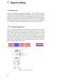
7.
Signal routing . . . . . . . . . . . . . . . . . . . . . . . . . . . . . . .
7.1 Introduction . . . . . . . . . . . . . . . . . . . . . . . . . . . . . .
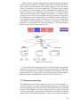
7.2 The signal routing layer . . . . . . . . . . . . . . . . . . . . . . .
42
42
42
4
.
.
.
.
.
.
.
.
.
.
.
.
.
.
.
.
.
.
.
.
.
.
.
.
.
.
.
.
.
.
.
.
7.3 When to transfer data . . . . . . . . . . .
7.4 Conclusions . . . . . . . . . . . . . . . .
8. Operating systems . . . . . . . . . . . . . .
8.1 Introduction . . . . . . . . . . . . . . . .
8.2 The OSEK specification . . . . . . . . .
8.3 Rubus OS . . . . . . . . . . . . . . . . .
8.4 Other . . . . . . . . . . . . . . . . . . .
8.5 Conclusions . . . . . . . . . . . . . . . .
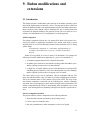
9. Rubus modifications and extensions . . . . .
9.1 Introduction . . . . . . . . . . . . . . . .
9.2 Hardware . . . . . . . . . . . . . . . . .
9.3 Memory setup . . . . . . . . . . . . . .
9.4 API calls affected by memory protection
9.5 Communicating signals . . . . . . . . . .
9.6 Signal routing . . . . . . . . . . . . . . .
9.7 Initialization . . . . . . . . . . . . . . .
9.8 Shutdown and restart . . . . . . . . . . .
9.9 Error handling . . . . . . . . . . . . . .
10. Discussion . . . . . . . . . . . . . . . . . . .
10.1 Summary and conclusions . . . . . . . .
10.2 Future work . . . . . . . . . . . . . . . .
Definitions and abbreviations . . . . . . . . . . .
References . . . . . . . . . . . . . . . . . . . . .
.
.
.
.
.
.
.
.
.
.
.
.
.
.
.
.
.
.
.
.
.
.
.
.
.
.
.
.
.
.
.
.
.
.
.
.
.
.
.
.
.
.
.
.
.
.
.
.
.
.
.
.
.
.
.
.
.
.
.
.
.
.
.
.
.
.
.
.
.
.
.
.
.
.
.
.
.
.
.
.
.
.
.
.
.
.
.
.
.
.
.
.
.
.
.
.
.
.
.
.
.
.
.
.
.
.
.
.
.
.
.
.
.
.
.
.
.
.
.
.
.
.
.
.
.
.
.
.
.
.
.
.
.
.
.
.
.
.
.
.
.
.
.
.
.
.
.
.
.
.
.
.
.
.
.
.
.
.
.
.
.
.
.
.
.
.
.
.
.
.
.
.
.
.
.
.
.
.
.
.
.
.
.
.
.
.
.
.
.
.
.
.
.
.
.
.
.
.
.
.
.
.
.
.
.
.
.
.
.
.
.
.
.
.
.
.
.
.
.
.
.
.
.
.
.
.
.
.
.
.
.
.
.
.
.
.
.
.
.
.
.
.
.
.
.
.
.
.
.
.
.
.
.
.
.
.
.
.
.
.
.
.
.
.
.
.
.
.
.
.
.
.
.
.
.
.
.
.
.
.
.
.
.
.
.
.
.
.
.
.
.
.
.
.
.
.
.
.
.
.
.
.
.
.
.
.
.
.
.
.
.
.
.
.
.
.
.
.
.
.
.
.
43
46
47
47
47
50
53
53
54
54
55
55
59
61
64
65
65
66
69
69
69
71
74
5
6
Acknowledgment
This report is a thesis for a master’s degree at Lund Institute of Technology.
A special thanks go to our supervising professor Karl-Erik Årzén at the Department of Automatic Control at Lund Institute of Technology as well as to Peter Hansson and Fredrik Latz, our supervisors at Volvo Technology.
Many thanks also to Kurt-Lennart Lundbäck and colleagues at Arcticus Systems
for valuable information on Rubus OS and very useful feedback.
We would also like to thank the people from group 6242 and 6260 at Volvo Technology for creating a great work environment.
A very special thanks goes to Mats Honnér’s mother in law for an endless supply
of crossword puzzles.
7
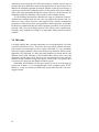
1. Introduction
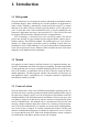
1.1 Background
The goal of the thesis is to investigate the software and hardware mechanisms needed
to maintain integrity while centralizing the execution platforms for applications in
todays vehicle. Normally a subcontractor would provide their own ECU to control
their part of the vehicle. This has resulted in growing numbers of ECUs the past few
years. To meet this trend, vehicle manufactures have a need for bundling the sub
contractor’s applications into larger, more powerful ECUs. This will raise the need
for integrity and fault tolerance mechanisms in the execution platform.
Volvo Technology is concerned not to favor any RTOS vendor. This led the
project into choosing an open standard for time-triggered RTOS aimed at the automotive industry - the OSEKtime standard. The original goal was to verify the functionality of a simple memory protection system by extending an open source implementation of the OSEK standards. It was soon realized that no implementation
exists with an open source license. Without a RTOS to modify the focus of the thesis
changed to an in depth theoretical examination.
1.2 Method
Our approach to ensure integrity and fault tolerance is to implement memory protection in combination with static time triggered scheduling. Through encapsulation
of each application into a memory container and limiting the access to memory outside of the container, an application will not be able to directly corrupt the data of
another application. The time-triggered schedule will guarantee execution time for
each application and by combining the two, a complete separation of applications
from different vendors is possible.
1.3 Course of action
The work began with a study of the OSEKtime and the Rubus operating system. After followed a study on memory protection methods which combined with a study of
the supervising company’s needs, led to an investigation of the hardware needed for
an implementation of the different protection mechanisms. The next step was to take
everything to a higher level and specify software structures to implement IPC (Inter
Process Communication). This naturally led to a specification of the basic IPC and
necessary changes needed to adapt these structures to a memory protected environment. The last area studied before our attention was focused upon extending Rubus,
was to look at how to integrate an external communication module, Volcano, and
make the communication transparent to whether the signal travels over a CAN-bus
or is local within the same ECU. With all the background theory in place a proposal
for modifications of the Rubus operation system was developed.
8
1.4 Result
The work has resulted in a proposal for updates of the Rubus operating system with
added memory protection. Rubus is a time-triggered RTOS from Arcticus systems
which was chosen upon failing to find a suitable OSEKtime implementation. The
thesis also contains a thorough analysis of the implications of memory protection
and methods to solve integrity and fault tolerance issues. A study of available microcontrollers targeted at the automotive industry has also been conducted and has
resulted in a preferred target platform for our implementation proposal.
9
2. Objectives
2.1 Requirements
Volvo Technology’s main goal is to reduce the number of ECUs in vehicles to reduce
costs. This is done by merging software from several vendors onto a shared piece
of hardware. Isolation between applications from different vendors and fault detection is needed due to legal and liability issues. Prior to the thesis it was decided that
the introduction of a time-triggered operating system is a preferable way of isolating applications for temporal integrity (i.e. allocation of the central processing unit).
Memory protection is a further addition to also guarantee data integrity. Finally, a
fault tolerant system should be capable of detecting errornous operations and implement ways to handle critical situations. Hence, we have the following basic needs
• the possibility of running several applications on one ECU
• introduction of a time-triggered operating system
• memory protection
• error detection and handling
• must confirm to previous basic requirements such as determinism and fault
tolerance issues
The boundaries of memory protection must be further defined. This is somewhat part
of the study although the system should aim at supplying the following property
• a subcontractor should be able to supply a piece of software that is protected
from software developed by other suppliers
Since the exact definition of such a component was not necessary for the first part of
the study, a piece of software with its own protected domain was simply be referred
to as a software component, without further definition. The software component was
later refined and compared to other terms such as applications and processes. The
concept is desccribed at the end of this chapter.
2.2 Desired features
As work progressed new features where discussed and some of them where added
to the objectives of the thesis. The possibility of running an event-based system in
conjunction with the time-triggered, was discussed early into the work cycle. The
event-based model has some beneficial properties that can be used for not-so-timecritical tasks utilizing the spare time of a time-triggered system.
A need to further optimize the system resource utilization (i.e. processing time
and memory) was stressed by Volvo. This led to a more modularized application approach in which the interpretation and practical definition of the software component
became an important aspect. A need for flexibility and small modules was taken into
consideration as the software component definition was refined.
The basic isolation requirement had to do with write protection between software components. The possibility of detecting also read errors is a natural extension.
10
Taking it even further, one may also consider internal faults, such as stack overflow
within a specific piece of software. Such aspects were also considered as memory
protection could allow them to be efficiently implemented. All fault detection is good
for isolation and identification of software errors. The system may become more tolerant if errors can be detected and dealt with at an early stage. Isolation of errors also
decrease development times.
2.3 Assignments
The work has been aimed at the following assignments
1. study and describe time-triggering and memory protection
2. study the effects of software isolation
3. choose a platform (hardware and operating system) for development and testing
4. propose extensions to the chosen platform
5. identify areas for further work
Aspects on fault tolerance, determinism, etc. are considered throughout the complete
study.
Assignment one is presented in Chapters 3 and 4. Following the discussion of
memory management, a selection of relevant hardware is presented in Chapter 5.
Chapters 6 and 7 handle the effects of memory isolation. Chapter 7 also discuss how
to implement a common transparent distributable communication layer. The choice
of operating system is discussed in chapter 8 and chapter 9 proposes some extensions.
Finally, further work is presented in chapter 10 after a summary of this report.
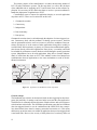
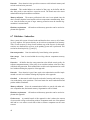
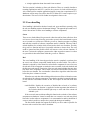
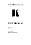
2.4 The software component
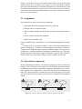
In todays distributed environment, sub contractors typically provide the vehicle manufacturer with a ”black box” in the form of an ECU hardware environment and the
controlling software. Software from different suppliers communicate over a bus network (typically CAN) independent of from where and whom the information originate. The vehicle manufacturer administrate the network and supply the developer
with vital information concerning the period, latencies and jitter of communicated
signals.
Application
architect
Application1
ECU1
Application
architect
Application2
ECU2
Application3
Application
architect
ECU3
Figure 2.1 In todays system, the developer supplies an application and the ECU.
11
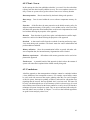
The primary purpose of the centralization is to reduce the increasing number of
ECUs in todays automotive systems. The first step then, is to relieve the developer
of the additional task of supplying an ECU and let them focus on the software application. It is necessary for the vehicle developer to involve a system coordinator to
handle the deployment of applications to ECUs.
Centralization causes a concern for application integrity as serveral application
may share an ECU. There are five main areas to this issue.
1. Guaranteed execution
2. Concurrency
3. Independence
4. Data consistency
5. Data privacy
Guaranteed execution time is realized through the adoption of a time-triggered system. Concurrency deals with the problems of sharing system resources. Software
must be guaranteed exclusive access to resources to avoid race conditions. Data consistency and privacy is in the context of other applications being able to modify or
read local data. Data consistency is primary as it ensures that malfunctional applications do not directly affect other applications. Data privacy is secondary and could
be excluded for performance reasons. Both are realized through a memory protection
system. Independence has to do with applications being able to function independently of with whom they share an ECU. This attribute restricts local interprocess
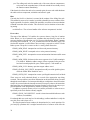
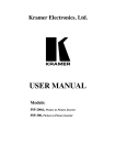
communication between applications to the same mechanisms as used in the distributed environment.
Component1
Component5
Application
architect
Application
architect
Application
architect
Component7
Component2
Component3
ECU1
Component4
ECU2
Component6
ECU3
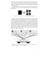
Figure 2.2 Applications are divided into several components.
General concept
The introduced new real-time environment is based on time-triggering but also incorporate the possibility of running event based tasks in one and the same application.
The difference is commonly discussed in terms of hard-real-time and soft-real-time or
critical and non-critical tasks. The OSEKtime specification states that for OSEKtime
(the time-triggered kernel) to run in combination with OSEK/VDX (the event/priority based kernel) there must be memory protection between the two. This means
that memory protection must exist within an application between time-triggered and
event-based tasks. However, the severity of faulty behavior of a task may differ not
12
because of its hard- or soft-real-time requirement but because of the function it performs. We therefore propose a different view where parts of an application are separated because of their function and not because of their real-time properties (although,
this may very well be tightly coupled). We call these isolated parts of an application
software components.
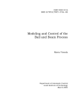
The proposed software component is a more flexible structure than separation
between hard- and soft-realtime. The OSEKtime separation is still possible through
design decisions.
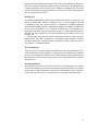
Figure 2.3 Software components are pieces of the puzzle creating an application.
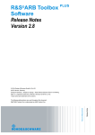
The basic isolation derived from the previous discussion, is that every software
component is memory protected individually. A further requirement is that software
components should be arbitrarily distributable over ECUs. This implies that they
are at least partially hardware independent. Software components can be supplied as
source code and compiled for a specific CPU but interactions with the system must be
performed through a common interface. Thus, the components are restricted to using
distributed communication protocols while communicating. Internal communication
between tasks of a component is not affected. Suppliers may find it preferable to
supply software components as compiled object code. In such case, also the CPU
architecture must be common to all ECUs or the supplier will have to be involved in
transfers of components between ECUs.
Component5
Application
architect
Application
architect
Component1
Application
architect
Component2
Component7
Component4
Component6
Component3
Component 1, 3, 5 and 6
Component 2, 4 and 7
System
configuration
ECU1
ECU2
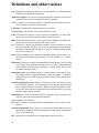
Figure 2.4 In the new system, a developer supplies a set of software components that can be
freely distributed over ECUs by the vehicle manufacturer.
13
3. Time-triggered scheduling
This chapter will introduce a time-triggered approach as used in the OSEK and Rubus
operating systems. We specifically discuss time-triggering and not event-triggering
since the former plays a central role in the proposed system, and the latter has been
around since long in the vehicle industry. Time-triggering does not necessarily imply
static scheduling, but since this is the case for both OSEKtime and the Rubus timetriggered kernel, it goes without saying for the remainder of this document.
3.1 Introduction
Time triggered scheduling is used in applications such as ABS breaks, All Wheel
Drive and other critical systems. Its main purposes are to guarantee deadlines and
execution time. Another feature, which is of interest from the centralizing point of
view, is the ability to separate applications from each other. In the time-triggered system, all tasks run under the same conditions as compared to a priority based system
where tasks are differently privileged. This causes problems between applications as
discussed in the problem formulation.
The time-triggered approach is relatively simple. This makes it easy to grasp and
get a complete view of a system. The predefined schedule allows us to make guarantees, even at 100% processor utilization.
If the system coordinator has the worst case execution times, periods, and deadlines for tasks within every application she can use the information to group the tasks
on forehand and possibly reduce the number ECUs required. Naturally, the system
coordinator may set restrictions to the worst case execution times in cooperation with
the application engineers, while the sub contractors sets the period and deadline restraints within each application.
3.2 Time-triggered tasks
It is important to characterize the time-triggered task and understand what makes it
different from its event-triggered counterparts. A typical event-triggered tasks has
four states
running The task is assigned to the CPU and is executing its instructions.
ready The task is ready to be assigned to the CPU. A task enters this state when it is
activated or preempted.
waiting The task is waiting for at least one event before it is ready to continue its
execution.
suspended The task is passive and can be activated.
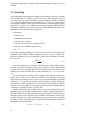
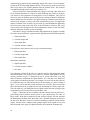
Figure 3.1A illustrate these states and the possible transitions.
For time-triggered tasks, the waiting state does not exist. This means that they are
not allowed to use blocking resources or wait for events. Another notable difference
is the direct transition from the suspended state to the running state. The execution
states and transitions of time-triggered tasks are shown in Figure 3.1B.
14
Suspended
activate
Suspended
terminate
preempt
Ready
preempt
Executing
start
release
terminate
activate
Ready
Executing
start
wait
Wait
A
B
Figure 3.1 Execution states of event-triggered (A) and time-triggered (B) tasks.
The time-triggered task runs periodically, leaving and entering the suspended
state upon each invocation. The event-triggered task would typically only leave the
suspended state at system startup and enter it again before system shutdown1 . It
would release the processor during temporary inactivity using the wait state. A timetriggered task is never ready without returning to the suspended state. It only releases
the processor if
• it terminates
• it is preempted
• an interrupt causes the processor to switch to an interrupt service routine
There is of course, also the possibility of the kernel identifying an error, causing the
system to enter a special state. This is seen as a special case and is not of interest for
the general discussion.
The time spent utilizing the processor between leaving the suspended state and
reentering it, is the execution time of the invoked time-triggered task. This time may
vary due to conditional statements and iterations in the code. The worst possible
execution time on any invocation is referred to as the tasks worst case execution time
(WCET).
Since the discussion has compared the time-triggered and event-based task, it is
worth pointing out the existence of a third type. Anyone familiar with OSEK/VDX
knows it as the basic task. Others commonly refer to it as a single-shot or one-shot
task. This task is similar to the time-triggered task but executes in the event-triggered,
priority based environment. It does not have a waiting state and hence, should always
actively perform its task when it has not been preempted by a higher priority task or
an interrupt. When the task is complete, it returns to the suspended state. A difference
between the single-shot task (due to its execution in the priority based environment)
1
Although several real-time systems also implement event-based tasks without the waiting state
(basic tasks in OSEK).
15
and the time-triggered task, is that the single-shot task enters the ready state as it is
activated.
3.3 Scheduling
The fundamentals of time-triggered scheduling is that through a worst case execution
time and definition of a deadline for each task, create a static schedule that allow
every task to meet its respective deadline. In general, building a schedule is NP-hard
(i.e. verifiable in nondeterministic polynomial time [O(nk ), where n is input and k is
a non-negative number]). However, the characteristics of the time-triggered system
makes it a wise choice to use deadlines for an heuristic approach. Earliest Deadline
First (EDF) scheduling is the common name for dynamic deadline scheduling. In its
simplest for we have the following requirements
• preemptive
• periodic tasks
• independent task execution
• each task t has a period Pt
• each task t has a worst-case computation time Ct
• each task t has a deadline requirement Dt
• Dt = Pt
In EDF, the scheduling technique is to always execute the task with the shortest time
remaining until its deadline. With the requirements met, it is easy to calculate CPU
utilization and make sure it is less than 100%, which is the requirement for all deadlines to be met.
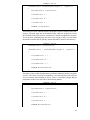
t=n
X
Ct
≤1
(3.1)
U=
P
t=1 t
In our static approach, we could base scheduling on this simple EDF principle.
However, the preferred technique used to create a schedule is usually undefined and
up to the end user. Note though, that basic EDF guarantees that we can find a valid
schedule up to 100% utilization. However, the requirement Dt = Pt is very restrictive.
One of the benefits of creating a static schedule is that analysis becomes very
simple. All we need to do to validate the schedule is to go through it and check
that all timing requirements are met. We can try to set some deadlines less than the
periods (Dt < Pt ), generate the schedule, and run through it to check validity. We
may sometimes be able to handle special cases and tweak the schedule by hand. We
could also use a more sophisticated computer program to generate schedules that try
to minimize for example the jitter of specific tasks.
Another benefit of the static schedule is the ease of use by the kernel. The system
scheduler simply runs through a schedule stored in memory. Dynamic approaches require the kernel to perform steps such as altering dynamic priorities and searching for
the highest priority task. On the down side, a schedule could consume relatively large
amounts of memory. In fact the schedule length may grow rapidly when increasing
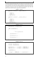
the number of tasks. The length can be calculated as the least common multiplier of
the periods of all scheduled tasks
Lschedule = lcm(P1 , P2 , . . . , Pn )
16
(3.2)
If the task count is kept small, the schedule length will most likely not be much of a
problem. However, when centralizing many tasks to one ECU, the length can become
very large. The need to keep the schedule small could potentially drive a system coordinator to limit the accepted periods to multiples of a given integer or set of integers.
This could force periods to be smaller than necessary and create an unnecessary load
on the CPU. This would also limit the flexibility for system developers.
The kernel may want to perform some special operations at the end of the schedule. Long intervals between these operations are not desired. Often, methods to schedule these operations to occur within the schedule are used instead. An example of
such a specific operation could be deadline monitoring.
Possitive aspects of time-triggered scheduling are
• possible to guarantee execution time pre-run-time
• easy to create reproducible results since the execution order is static
• deterministic behavior
• even at high load, we can guarantee deadlines
• easy to analyze the schedule
and the following drawbacks are the main disadvantages
• relies on polling for events.
• schedule must be defined pre-runtime.
3.4 Resource allocation
It is clear that dynamic memory allocation gives rise to fragmentation issues and the
possibility of running out of memory. Both result in a system with non deterministic
behavior. This is generally unacceptable in a real-time system and especially for the
hard-real-time nature of the time-triggered system.
In a time-triggered system, all task can share the same stack. This is due to the
fact that a preempted task will never continue its execution until the preempting task
has exited, thus restoring the stack. For every task, there must be a defined maximum
stack usage. The total allocated stack memory must be as large as the largest sum
of maximum stack usages within the schedule, i.e. to calculate the stack size, step
through the schedule. Every time a thread starts, add its maximum usage to the stack
size. Every time a thread exists, remove its maximum usage from the size. The largest
value obtained during this procedure is the required stack size.
To be able to guarantee the deterministic features of a time-triggered system, resources must be statically defined. Although it is the most common case, off-line
allocation is not necessarily required (resources could be statically set up during system initialization). The off-line scheduling described earlier, is an allocation of the
central processor unit resource.
3.5 Synchronization
Since time-triggered tasks are not allowed to block, resource management must be
taken into consideration while scheduling the tasks. Mutual exclusion on shared resources must be guaranteed by the scheduler. Common techniques such as semaphores
17
and mutexes are not allowed at all. Thus, tasks sharing a common resource may not
preempt each other. Methods to ensure no preemption between certain tasks can be
added to the scheduling algorithm. Sorting the schedule so that the task writing to a
resource precedes the tasks reading the resource is also possible. This ensures minium
delay to the signal transmitted through the resource. However, all this increases the
scheduling complexity and makes it less possible to find a suitable solution.
It is the blocking restriction that eliminates the usage of synchronous resources.
Asynchronous communication does not cause any problems and atomic sized variables never cause concern. However, time-triggered tasks could also communicate
grouped sets of data as long as the system guarantees atomic operations. It must then
be taken into consideration that any atomic operation not intrinsic to the processor,
basically ”halts” the system during operation. This affects system responsiveness.
Preferably, only methods fast enough to be neglectable during analysis should be
available.
3.6 Idle time
It is highly unlikely that a real-time application (or several applications) will reach
a processor utilization of 100%. This can be due to precedence relations and exclusion relations between threads as well as resource constraints. It is very uncommon
that a time-triggered schedule will result in full processor utilization. When a system
approaches very high loads, it is likely that some deadlines are missed and no valid
schedule can be found. Therefore, a valid schedule almost always leave a few (and
often more) percent unused. Also, the worst case execution times used to create the
schedule are worse than the average time spent to execute tasks, so in general, there
is even more free processor time than the schedule suggests.
Both Rubus and OSEKtime use this spare capacity to execute an event-triggered
sub-system. In Rubus, it is an incorporated part of the operating system. In OSEKtime, it is done by running an OSEK/VDX system in the idle task of the timetriggered system.
18
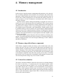
4. Memory management
4.1 Introduction
In this section we introduce memory management and protection to solve the problem of isolating applications from each other. We will discuss and evaluate some
approaches, starting with the most basic ideas as used in older operation systems. In
its basic form, memory management is not concerned with memory protection. Instead, its purpose is to create a multiprocess environment and to utilize memory as
efficiently as possible.
Dynamic memory and the loading and unloading of programs into and out of
memory, gives rise to a phenomenon known as fragmentation. This is of great concern
in a general purpose system and therefore memory management has developed a lot
within this area of computer science. For special purpose systems we can more or
less predefine memory and thereby avoid fragmentation. Another problem solved
by predefined memory is that of relocation. In a general purpose multiprogramming
system, processes will be swapped in and out of memory. It is impossible to determine
exactly where in memory a program will be placed and so, static addressing becomes
a problem. We will not look into this as our presumptions are that the complete system
has been set up off-line.
Our special purpose system will greatly reduce the complexity of memory management. The statically defined system does not need to be concerned with effective
memory swapping and there is no need for logical addressing or relative addresses
and address redefinitions.
4.2 Memory setup with software components
Each software component contains the memory of the included tasks stack, data
memory and code. The code is often located in flash memory and therefore has a
natural separation. The data memory must be shared between all tasks of the same
software component. This to allow direct communication between these tasks. The
stacks can be separated go gain security. This would require one extra memory region
of the hardware compared to when tasks share memory for the stacks. It is desired
that the stack of the executing task is surrounded by small segments of memory with
write and read protection acting as trip wires for stack overflows.
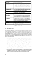
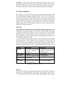
4.3 Criteria for evaluation
The memory protection techniques discussed in this section are evaluated through a
list of pros (+) and cons (−). A property may have more than one positive sign if
it is very good and more that one negative if it is very bad. This marking is relative
to the other concepts. The (±) notation is used for uncertainties. Every property is
followed by a short comment to describe why it was chosen as a positive or negative
aspect. Choices are made from what would be expected to gain from the concept but
also as a result of the hardware support found. Table 4.1 lists the involved evaluation
criterias with a short description.
19
Analyzability / Predictability
Is it easy to analyze and predict system properties
and are the results certain?
Overhead
The extra work conducted by the CPU when introducing access rights (read/write, user/supervisor)
and additional functionality such as logical addressing.
Functionality
The protection properties supported.
Context Switch
The work load required to update the memory management system during context switches.
Initialization
The work load required to initialize the memory
management system during startup.
Memory utilization
How well the memory is utilized.
Portability
Can we expect to be able to easily port to several different architectures or will implementations be very
specific.
Complexity
Simpler systems will be easier to work with and understand. This could decrease development time and
be less error prone than complex alternatives.
Cost
Expected cost relative to other approaches.
Remarks
Negative if the concept imposes restriction not included in the properties above.
Table 4.1 Evaluation criteria
4.4 Base & Bounds
With simple base and bounds, an application owns a single private memory area. Two
registers define the starting address of the memory area (the base register) and the
size (bounds register). Every memory reference is compared to the bounds register
and then added to the base register. An error trap is triggered upon bounds violation.
The kernel runs in supervisor mode unrestricted by any bounds. This approach is
attractive due to its simplicity and minimal overhead. However, it is not useful to our
purpose for several reasons:
1. Since every process is restricted to a single continuous partition we cannot execute directly from Flash-memory. This would require a very large RAM to
host all executable code and data. We could instead load tasks into RAM at execution time but that would increase the time for context switches enormously.
Also, we would need to allocate and use an area of RAM large enough to fit
the largest executable entity to avoid external fragmentation issues.
2. The stack memory cannot be separate from static/global memory. This allows
the stack to grow into data memory and pointers to corrupt the stack without
notice. Detection would, of course, not solve invalid pointers and overflowing stack issues but it would simplify debugging and could spot errors before
serious damage is done.
3. For optimization purposes and code reusability, we may want tasks to share
common parts of memory. One example is shared libraries and global constants. This may become problematic with only one partition per task.
20
4.5 Partitioning / Segmentation
Base & Bounds is too restrictive but it is not far fetched to think that the addition
of a few more simultaneously active regions would be enough to serve our purpose.
Partitioning simply refers to dividing the memory into several regions. In its basic
form, every partition hosts a complete process. The term segmentation can be seen
as an extension, where every process is divided between several partitions. These
partitions are called segments. We could, for example, separate a program into a code,
a data and a stack segment. For dynamic systems, this is useful for relocation issues
as well as for reducing the size of partitions, making for better memory utilization.
The segmentation aspect does not need to be explicitly included in the hardware,
especially in our static system. The off-line memory definition frees us from the need
to use any logical addressing. We are free to compile all modules into one package
and use direct memory addressing as long as we have the ability to define offsets
for each module (linking stage) and restrictions on different areas in memory (during
execution).
The realization could be done in several ways by exploiting opportunities in simple or more complex memory systems. Our goal though, is to use a system that is
as simple as possible. Typically, systems that support simple partitioning have one
or more drawbacks. Basic support is most commonly found on low-end systems and
with the main ambition to separate kernel and user space. Another problem is the lack
of standardization. In Chapter 5 however, we will discuss two hardware architectures
with good potential. These micro-processors have embraced the concept of a MPU
(Memory Protection Unit). This is a simple and fast unit designed for special purpose
systems, as opposed to the MMU (Memory Management Unit), suitable for general
purpose designs.
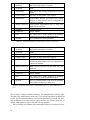
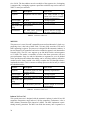
Pros and cons
We state two cases for pros and cons, weak hardware support (Table 4.2) and strong
hardware support (Table 4.3). The first case is based on what is typically found in
older, commonly used hardware specifications. The second case is based on the concept of MPUs which comes really close to fulfilling all our requirements.
4.6 Paging (the MMU)
Unequal fixed-size as well as variable-size partitions are inefficient memory management techniques in general purpose systems. With paging, main memory as well as
processes are divided into equal fixed-size, relatively small chunks. Process chunks
are referred to as pages. Pages can be assigned to available chunks of memory, called
frames. Frames are not required to be aligned in phyiscal memory, although to processes the virtual memory looks continuous. MMUs are designed for paging systems.
Paging is often associated with virtual memory. It is important to distinguish between virtual memory and logical addressing. Virtual memory extends logical addressing with page swapping to a larger and slower memory. This adds a huge overhead and is of no interest in a real-time environment.
Utilizing a memory management unit
When using a MMU the CPU does not have direct access to the memory. All communication passes through the MMU. The MMU interprets the logical address the
21
+
Analyzability / Predictability
Simple to calculate the exact cycles required to update the limited amount of registers.
+
Overhead.
None
−
Functionality
Only able to deny writing, no detection of read violations.
+
Context switch
Fast since we only update a few registers.
+
Initialization
None needed. Regions are fetched from constant
memory or in the extreme case even compiled in as
instruction constants.
−− Memory utilization
Large internal fragmentation due to a large minimum size for partitions.
−
Portability
Lacking standards
+
Complexity
Simple method.
+
Cost
We expect such a simple method to be relatively
cheap and to be found in older architectures.
−
Remarks
Few simultaneously active partitions.
Table 4.2 Partitioning/Segmentation - Weak hardware support (e.g. MPC555)
+
Analyzability / Predictability
Simple to calculate the exact cycles required to update the limited amount of registers.
+
Overhead.
None
+
Functionality
Read, write and no access support.
+
Context switch
Fast since we only update a few registers.
+
Initialization
None needed. Regions are fetched from constant
memory or in the extreme case even compiled in as
instruction constants.
±
Memory utilization
Better than the previous case but could still cause
problems.
−
Portability
Lacking standards
+
Complexity
Simple method.
+
Cost
We expect such a simple method to be relatively
cheap and to be found in older architectures.
±
Remarks
Still very limited amount of simultaneous partitions
but probably satisfactory in most cases.
Table 4.3 Partitioning/Segmentation - Good hardware support (e.g. 940T ARM, MPU support)
CPU is using to a physical address in memory. This translation from virtual to physical adds some overhead to the access time. To overcome long delays the MMU has
a cache, the TLB (described below), where recent translations are stored. The drawback is different access times between pages cached in the TLB and pages not yet
cached, which implies a system with poor real-time qualities.
This is normally not a problem since deterministic behavior is not crucial in com-
22
mon operating systems. In hard real-time applications this cannot be tolerated, thus
using a MMU in an ordinary fashion is not a viable solution. In our case, we are dealing with static predetermined memory areas. It is possible to determine the maximum
overhead caused by table lookups during the execution of a task but it is not possible
to determine exactly when TLB misses occur, hence, the system cannot be said to
be completely deterministic. The question is whether exact knowledge of when the
overhead occurs is required.
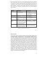
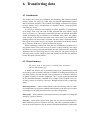
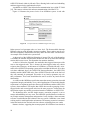
The translation look-aside buffer (TLB)
The TLB is a small, very fast, array of registers. Each entry in the TLB contains a
virtual page address and a corresponding physical page address. Depending on page
table implementation, the TLB also include a status field with information regarding
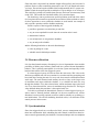
page sizes and access rights. A typical TLB has about 32 registers. Figure 4.1 shows
a sketch of a simple TLB.
Figure 4.1 TLB Layout
Deterministic memory protection using a MMU
In this approach we discuss the possibility of completely deterministic memory protection using a memory management unit (MMU). A problem with all implementations utilizing a cache is that it is hard to make it deterministic due to cache misses.
In this approach we will consider the case when not using more memory than the
cache (TLB) can contain at the same time. This will ensure a fast and deterministic
behavior since no TLB misses can occur.
The problem lies in filling the TLB during context switch in a fast and efficient
manner. TLB misses are handled in different ways for every processor family. In
some architectures a TLB update is done completely in hardware without the OS
ever knowing. This makes it hard to control the update. One way would be to generate a memory access to every page a task needs, during its context switch. The
overhead added to every context switch is an interrupt for every page associated with
the process and the time it takes to read these from memory. This method will need a
separate analysis to prove that the TLB will actually contain all relevant pages when
a context switch is finished, else deterministic behavior will not be guaranteed. More
on how to fill the TLB can be read in [9].
Another way of handling a TLB miss is to let the programmer handle the update.
This is called a software update. Whenever a TLB miss occurs an interrupt fires and it
is up to the interrupt routine to update the TLB. In this way the kernel is in full control
23
of the update process. This implies some demands on the instruction set of the CPU.
There must be a way to update a specific entry with given address. With such a feature
it would be possible to pre-fill the TLB during a context switch and then eliminate all
further TLB misses for the next task to execute. The TLB interrupt routine mentioned
above would only execute every time a process tries to access memory outside of its
boundaries, thus a fault.
Filling up the TLB impose a large overhead on context switches, making it an
unwise decision to perform a complete context switch on every kernel interference.
There must be a way for the kernel to execute without refreshing the TLB. One way
would be to reserve space for the kernel in the TLB (for every application) and protect it with super user rights. This would on the other hand waste some TLB entries
and probably impose a demand of variable page sizes to reduce internal memory
fragmentation.
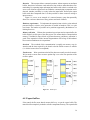
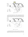
Another possibility would be to combine the TLB with some segmentation technique. In this setup the TLB will impose a more fine-grained protection between tasks
while the registers setting up the segments divide the memory into segments defining
OS specific memory, program memory and data memory (referred to in Figure 4.2 as
Segment 1, Segment 2 and Segment 3). The TLB protection is only active in segment
2 and 3. To access memory in segment 1 the task must be in supervisor mode. This
makes it ideal to store the kernel in segment 1 since it is fast to switch between user
and supervisor mode.
Figure 4.2 RAM layout
Pros and cons
We state two cases of pros and cons. One for full utilization of the MMU with TLB
updates performed as needed (Table 4.4) and one where the TLB is updated completely during the context switch (Table 4.5).
24
−− Analyzability / Predictability
−
Overhead.
Complex to analyze and cannot be exactly predicted.
It may not even be possible to guarantee an exact
overhead caused by table lookups.
TLB misses cause overhead.
++ Functionality
Read, write and no access support for user and supervisor modes. Implicitly adding logical addressing.
+
Context switch
Update one or a few MMU registers.
−
Initialization
Requires setting up the MMU functionality.
±
Memory utilization
Depends on available page sizes and TLB entries.
Minimum of 4 kb page size seems to be standard but
support for smaller sizes exist. TLB with 32 entries
are common but larger and smaller variants exist.
+
Portability
MMU standard.
−
Complexity
Complex technology.
+
Cost
The MMU is a well spread technology and is quite
cheap.
+
Remarks
No further negative aspects found.
Table 4.4 MMU - Full utilization
+
Analyzability / Predictability
Requires a careful analysis to guarantee no TLB
misses. Predictability is good if this requirement is
met.
++ Overhead.
None. TLB lookups are included in the processor
pipeline.
++ Functionality
Read, write and no access support for user and supervisor modes. Implicitly adding logical addressing.
−
Context switch
Extensive update of the TLB entries.
−
Initialization
Requires setting up the MMU functionality.
±
Memory utilization
Depends on available page sizes and TLB entries.
Minimum of 4 kb page size seems to be standard but
support for smaller sizes exist. TLB with 32 entries
are common but larger and smaller variants exist.
+
Portability
Special MMU requirements.
−
Complexity
Complex technology.
−
Cost
Advanced MMUs are new to embedded systems
+
Remarks
TLB and page size may restrict available memory to
applications/tasks.
Table 4.5 MMU - TLB update during context switch (deterministic memory protection)
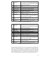
4.7 External hardware
In this section we will have a look at an example of a memory protection system using
an external programmable logic device attached to the memory bus. Two protection
25
techniques are discussed, a variant of partitioning and more advanced version with
similarities to a MPU or MMU. It is material for discussion and should in no way
be thought of as a recommendation for implementation. However, to create a clear
picture we go into some basic details and therefore it is worth pointing out that
• The name of pins, registers or any other component are not in any way related
to a real set-up. Names may coincide with pins found on a real implementation
performing a completely different task or with different or additional synchronization.
• The PLD memory controller implementation is always referred to as the PLD
as to not confuse it with the memory controller of the microprocessor.
PLD internals
The PLD controller is meant to function as a simple comparator used to partition
memory. No logical addressing is involved so the PLD does not need to perform any
conversions. Functionality is very similar to partitioning but could be extended with
additional functions since we are in control of the hardware implementation.
We consider two distinct operational techniques. One is where the PLD knows
nothing of applications and tasks. In this case, the PLD works with a small set of
registers that define memory protection for a fixed amount of partitions at the current
point in time. These registers need to be updated by the kernel whenever there is a
context switch. The other variant is where the PLD knows all memory information associated with applications and tasks. In this case, the PLD keeps a record of memory
information for every application and/or task. The kernel simply updates applicationand task-id’s when a context switch occurs.
The latter case requires an extensive initialization during system boot and a more
complex PLD module. The former requires more work during a context switch. The
kernel needs to lookup the memory definition of active application and task, and use
this information to update the PLD registers. Not many registers need an update, but
relative to the latter case, the update process would take considerable time. However,
relative to the tasks, the context switch could probably still perform really well (e.g.
compared to updating a TLB).
Whichever way we choose to implement the PLD, we need to develop a short and
fast algorithm for boundary comparison. To do this, restrictions may be imposed on
how memory regions are defined (e.g. sizes and starting addresses to the power of
two). If it is possible to create a fast enough PLD able to define regions of any size
and located at any offset in memory, it would be a great argument for this approach.
General operation
This section applies to Figures 4.3, 4.4 and 4.5.
The PLD waits for the Operation Enable pin to become active. This signals that
either a read/write or a PLD control operation is in progress. A bit in the MemCtrl
array is used to determine if the kernel is sending a PLD control operation. The
MemInt, MemCtrl and MemStat ports are used by the kernel to operate the PLD and
should be accessed by the kernel only.
In case of a regular memory access operation (Control signal bit inactive) the
PLD will compare the address to an active memory partition scheme. This scheme
has areas with read only, read/write or no access permission. Write operations are
signaled by the Write Enable pin being active. When an invalid request is sent the
PLD fires an interrupt through a dedicated interrupt pin. The kernel gets information
about the invalid action through the status port.
26
A simple PLD implementation could use the Control bus to switch between user
and supervisor modes. Since there is no logical addressing involved the supervisor
gets direct, unrestricted access to memory and the PLD is simply put into an idle state.
It is common for a memory controller to also include supervisor access permissions
on a memory region basis (e.g. per page in a paging system). This could be useful to
restrict also the kernel and aid in detecting any malfunctions.
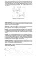
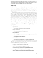
Hardware setup (wiring) considerations
In the case of the Observer setup (Figure 4.3) the PLD simply listens in on all communication. In the Gateway setup (Figure 4.4) the PLD intercepts communication
and forwards it to the memory only when access is granted. When a read error occurs
the PLD fires an interrupt and the kernel has the possibility of resolving the issue.
The observer setup has no ability to halt an ongoing write operation, thus no write
protection.
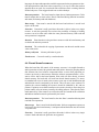
The extended observer case (Figure 4.5) has a solution to the write protection
problem. The PLD is able to inactivate the WriteEnable input of the memory with
an AND-gate. A potential problem with this setup is that it could disturb the timing
requirements of pin activation/deactivation, especially if flank-triggering, and thereby
cause erroneous results. It might also not be hard to ensure that the PLD acts fast
enough to actually cancel the operation before some part of the memory has been
altered.
The gateway case lets the PLD handle all transmissions as it sees fit. This setup
has the ability to completely hide restricted memory whereas the former cases actually allow applications to read data with the addition of the kernel being notified. To
make this a robust implementation we allow the use of extra wait states to analyze
permissions and thereafter forward data to the memory or return some null (zero or
undefined) result and fire the violation interrupt. The setup could potentially decrease
performance by adding overhead to memory operations but also increase robustness
and portability.
The observer cases, without synchronization registers, will only require the address signal to pass through short gate logic before a result is output. It is not uncommon for a memory operation to include one or more synchronization cycles where
e.g. the Write Enable pin is active and the address is on the bus, however the data is
not yet transferred to the data bus. Such a stage would probably be enough for the
PLD to conclude its result and cancel the operation.
Timings must be carefully considered and studied for each and every case. Neither can we take for granted that switching a single input reliably and effectively
cancels the operation, other problems could arise due to not following protocol.
Another definite problem is accessing on-chip memory. The micro-controller
must support an external slave device that is allowed full access to internal memory or we have no choice but to use external memory.
In the pros and cons lists 4.6, 4.7 and 4.8, we only consider the different hardware
setups. The PLD boundary setup affects context switch initialization in all cases. In
the two cases discussed earlier one leads to a fast finalization but a slower context
switch and vice versa. The flexibility given by creating a specialized PLD allows us
to make this a later design issue. However, it is important to keep this in mind when
comparing these variants to other concepts.
27
Figure 4.3 Observer layout
Figure 4.4 Gateway layout
Figure 4.5 Extended observer layout
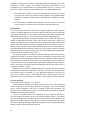
4.8 Software techniques
It is tempting to exclude memory protection through software techniques because of
the extreme overhead it would cause. For pure software implementations this could be
justified but software techniques could potentially also be handy to support features
28
+
Analyzability / Predictability
The hardware analysis could be quite complex but is
of no relevance to the kernel/application developers
and administrators. Knowing the hardware specifics
implies good predictability.
Overhead.
None.
−− Functionality
No write protection.
±
Context switch
Depends on the chosen implementation
±
Initialization
Depends on the chosen implementation.
+
Memory utilization
Designed to fit the purpose.
+
Portability
Interaction with memory make coupling with surrounding more complex.
−
Complexity
The concept is simple enough and kernel implementation can be made fairly simple. The hardware interaction could be very complex.
−− Cost
−
Hardware development and the addition of external
hardware increase costs.
Remarks
May not be able to utilize internal memory.
Table 4.6 External PLD - Observer setup
+
Analyzability / Predictability
The hardware analysis could be quite complex but is
of no relevance to the kernel/application developers
and administrators. Knowing the hardware specifics
implies good predictability.
−
Overhead.
Extra wait states delays memory access.
+
Functionality
Read and write protection.
±
Context switch
Depends on the chosen implementation
±
Initialization
Depends on the chosen implementation.
+
Memory utilization
Designed to fit the purpose.
+
Portability
As long as the micro controller supports wait states.
−− Complexity
The concept is simple enough and kernel implementation can be made fairly simple. The hardware interaction could be very complex.
−− Cost
Hardware development and the addition of external
hardware increase costs.
−
Remarks
May not be able to utilize internal memory.
Table 4.7 External PLD - Gateway setup
perhaps lacking in hardware. However, we have found pure software techniques that
indicate an acceptable performance loss. Such losses could be compensated with a
faster processor. The documentation of such techniques is very sparse and mostly
teasers introducing the reader to current research. The general idea is to use off-line
analysis through theorem provers (the common name for artificial intelligence logic
analyzers) and add instructions to compiled code in potentially dangerous areas.
29
+
Analyzability / Predictability
Knowing the hardware specifics implies good predictability.
−
Overhead.
None.
+
Functionality
Read and write protection.
±
Context switch
Depends on the chosen implementation
±
Initialization
Depends on the chosen implementation.
+
Memory utilization
Designed to fit the purpose.
−
Portability
Interaction with memory make coupling with surrounding more complex.
−
Complexity
The concept is simple enough and kernel implementation can be made fairly simple. The overall hardware/software interaction however, could be quite
complex.
−− Cost
−
Hardware development and the addition of external
hardware increase costs.
Remarks
May not be able to utilize internal memory.
Table 4.8 External PLD - Extended Observer setup
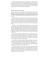
The most basic approach would be to add address checking or restricting code
at every memory access. Such an approach would create enormous amounts of overhead. To improve it, we could let the analyzer allow code that access static addresses
within acceptable areas. This could cover a large part of the accesses made in our
predefined system. The analyser must also take care of the increment of pointers and
other ways to access memory in a more dynamic manner. This is when things start to
get complex and it becomes hard to guarantee complete protection.
We state a hypothetical pros and cons list for a pure software solution in Table
4.9. The few and short introductory articles we have encountered claim that write
protection can be ensured with as small overhead as 4%. Incorporating read error
detection, increases the overhead a lot.
4.9 Conclusions
The MMU has established itself as a standard for memory management and memory
protection, at least for the desktop market. It seems that many designers of embedded
real-time systems blindly pursue the idea of embracing the MMU concept and use it
in their systems. For dynamic systems, this is the best choice as the paging system
of MMUs is well suited for dynamic allocation and supports logical addressing. For
static systems, the MMU supports features that are beyond the requirements.
The non determinism of TLB misses is not the largest concern. It is clear that in a
static system, the amount of misses is restricted and could be calculated or determined
through a trace utility. Also, the overhead of loading an entry into the TLB is very
small compared to other delays in most systems. The flaw of the MMU in our targeted
system is its complexity. Whether or not this complexity is costly is unclear. Usually
we have to pay for the development of advanced systems but the availability and
standardization of MMUs reduce their relative cost. There are other concerns to the
MMU. Kernel development will be more challenging on a complex system. The fact
30
−− Analyzability / Predictability
It is hard to guarantee that the analyzers will find
every possible case access violations.
−− Overhead.
Lots of overhead compared to hardware approaches
(although some argue that simple write protection
only gives about 4% overhead on average).
+
Functionality
Could do almost anything but adding functionality
will increase overhead.
+
Context switch
None since everything is within the application code
itself.
+
Initialization
(Like above).
+
Memory utilization
Quite exact bounds could be used.
−
Portability
The method could work on object code generated by
the compiler.
−− Complexity
Severe.
−
Cost
Extensive development cost. Low production costs
but fast processors are needed to compensate for
added work load.
−
Remarks
Adding security code will increase program size.
Table 4.9 Software techniques
that TLBs consume relatively large amounts of power could be a serious issue in
small embedded systems but for a vehicle this may be more or less indifferent. The
last and most serious property is the paging system. Paging will always suffer from
a minimum page size creating internal fragmentation issues, reducing the memory
utilization.
It is more fitting to use the simpler MPU approach, based on the usage of a simple
partitioning/segmentation setup with static addressing. Notably, this can be deduced
by simply considering the respective names of these systems. The Memory Management Unit is designed for complex memory management. Our static system does not
make use of such advanced techniques as dynamic allocation and virtual memory.
All we require is memory protection, hence, the Memory Protection Unit suits well
with our purpose.
Creating specialized hardware or using a software approach can be excluded because of the complexity, timely development and (at least for hardware development)
the large costs involved. Hardware would have been a interesting approach to challenge the wide spread MMU concept. However, the market analysis, partly presented
in the following chapter, has proven the availability of simpler, sufficient hardware
utilizing MPUs.
31
5. Hardware support
5.1 Introduction
In this section a number of potential microcontrollers are compared. The hardware
is a selection of the controllers that have been investigated [26], [27], [28], [29],
[30], [31], [32], [34], [35] throughout the thesis work. What distinguishes these microcontrollers are that they have a suitable memory protection mechanism and additional components such as a CAN bus. Almost all of the microcontrollers are marked
“suited for automotive industry”. This means the device has an operational temperature range from -40 to 80 degrees Celsius. There are often more than one candidate based on the same architecture, with minor differences. To reduce the amount
of presented controllers, only the most appropriate from each of the architectures is
included.
Note that the text makes no distinction between the terms microcontroller and
microprocessor. The devices are refered to as microcontrollers or in a shorter form as
controllers or processors.
5.2 Requirements
Segments The number of active segments the memory can be divided into is important. Basically there must exist at least three areas. Then the memory can be split
into the following areas: Currently running application, kernel, and the rest of the
memory. This is a simplified picture of our memory protection scheme. The size and
placement restrictions are also of importance. Normally there exists a minimum size
to a protected region and starting addresses are limited to a certain set. These requirements are implications of speed and resource optimizations within the hardware.
Access rights The possible access rights for each block or segment are of course
crucial. No access, Read/Execute, Write and Read & Write are the common levels.
Necessary levels are Read/Execute and Write & Read. These are also the minimum
requirements.
Run modes There must be a way of disabling the memory protection. The kernel
and other trusted code (such as drivers) need full access to the applications memory
pools. This is often called supervisor mode and user mode. When the processor is put
in supervisor mode the execution application will have full access to the complete
address range. This feature is very common and included in every modern microcontroller.
Run mode handling How the handling of supervisor mode is implemented in hardware has a major impact on low level memory protection implementation. The overhead of entering supervisor mode is crucial for performance and should not be too
large. If the mode can be changed through an instruction, limiting the address range
from where supervisor mode can be entered is also an important feature, but not necessary.
32
Performance Rather fast processors are desired but not required. Our focus is the
performance impact relative to the system running with or without memory protection. Since applications are supposed to be merged into running on the same ECU,
the end result will require a processor that is much faster than today’s standards.
5.3 Microcontrollers
The remainder of this chapter will introduce the following microcontrollers which
all support partitioning or paging: ARM 940T, MPC 555, MPC 5554, Infineon TriCore 1765 and Renesas SH7760. In addition to these, more or less every controller
designed for the automotive industry and with some sort of memory protection has
been studied during the work. The ones described in this chapter represent the vast
majority of the most suiting hardware the market has to offer. Every controller is
briefly presented with a short description and a list of pros and cons based on the
requirements described previously.
ARM 940T
This microcontroller is designed with the automotive industry in mind. It is a general controller for embedded systems. It has no internal CAN-controller and is not
certified for the automotive industry. The 940T has a MPU and thus uses simple
partitioning as protection mechanism. There exist a sister processor to the 940T, the
920T which sports a complete MMU instead of a MPU. This is not subject to further investigation by us, due to various reasons. One being that it has no easy way of
controlling the content of the TLB.
The 940T MPU has 8 available segments. They are divided into a base address
and an segment size. The base address must be a multiple of the segment size. The
minimum segment size is 4 kb, which is very large in relevance to our target system.
The processor also has the possibility to turn off cache ability of segments. This will
improve deterministic behavior. Table 5.1 shows the pros and cons for this processor.
Feature
Description
Pro or con
Segment
8 data and code segments
with size limitations. See
note above.
8 registers are very nice but
the min. size will cause some
wasted memory.
Access rights
R, R/W
Good support
Run modes
User mode, supervisor mode.
Average support.
Run mode handling
Not specified
Performance
185 MHz RISC processor.
Harvard architecture.
Very good performance.
Table 5.1 Summarize of ARM 940T
MPC 555
This processor is PowerPC compatible and developed with the automotive industry in
mind. It has 2 CAN controllers and is operational in the temperature range -40 to 125
◦ C. It has a MPU and no MMU. The MPU supports 4 data segments with a minimum
33
size of 4 kb. The base address must be a multiple of the segment size. Overlapping
is supported. By overlapping segments a protection with 4 kb steps can be achieved.
Table 5.2 states pros and cons.
Feature
Description
Pro or con
Segment
4 segments with size limits.
The small amount of segments will lead to internal
memory fragmentation.
Access rights
R, R/W.
Average support
Run modes
User mode, supervisor mode
Average support
Run mode handling
Not specified
Performance
40 MHz RISC processor.
Harvard architecture.
Slower than the average of
the other compared CPUs.
Table 5.2 Summarize of MPC 555
MPC5554
This processor is a new PowerPC compatible processor from Motorola. It looks very
promising since it has both a MMU with a 24 entry fully associative TLB and a
MPU supporting 8 registers. The processor is designed for the automotive industry. It
has two internal CAN-controllers and can be extended to support Local Interconnect
Network (LIN). The CPU core supports up to 600 MHz but this variant operates
at 133 MHz. This makes it reasonable to believe that future processors will have
great performance. Page size and size limitations on segments are yet to be defined
in the specification and without that nothing can be said about memory utilization.
Another specific feature needed is the ability to update the TLB through softwareimplemented routines. This is common on desktop processors but has not yet reached
the embedded market.
Feature
Description
Pro or con
Segment
8 segments with size limits.
24 entry in TLB
Memory fragmentation.
Access rights
R, R/W.
Average support
Run modes
User mode, supervisor mode
Average support
Run mode handling
Not specified
Performance
133 MHz RISC processor
Maybe enough for a real implementation.
Table 5.3 Summarize of MPC 5554
Infineon TriCore 1765
This special processor is designed with the automotive industry in mind. It has full
automotive temperature range and two CAN bus controllers. Furthermore, it has a
MPU (Memory Protection Unit) instead of a MMU. The MPU implements a partitioning memory protection. The MPU can divide the memory into 4 segments at a
34
time. The processor can hold two sets with 4 segments each. In this way 8 partitions
can be held but only 4 can be active at same time. Switching between the two sets
of partitions is fast. When entering supervisor mode the memory protection is not
switched off. Context switches are fast. Store and load of half of the registers are
done in hardware. A complete context switch of all registers can be done in 2 clock
cycles. The CPU has a frequency of 40 MHz, a bit slow but would be sufficient in
todays vehicles.
Feature
Description
Pro or con
Segment
2x4 data segments. 2x2 instruction segments
4 segments are just enough
but nothing more. Very fine
grained and precise segment
limits is a plus.
Access rights
R, R/W, X.
Good support
Run modes
User mode, User mode with
peripheral access, supervisor
mode
Above average support with
two user modes.
Run mode handling
Fast context switches and
run mode switches. Does not
seem to have any method of
limiting mode changes.
Performance
optimized.
Have all necessary features.
Performance
40 MHz RISC processor. 3
parallel pipelines which are 4
steps deep. Harvard arch.
Slower than the average of
the other compared CPUs.
Table 5.4 Summarize of Infineon TC1765
Renesas SH7760
The SH7760 processor is based on the SH4 platform from Hitachi. Although it does
not fulfill the automotive requirements or is a target platform for Rubus, we feel it is
still worth mentioning. This architecture has a very good MMU. The MMU supports
64 data region and four instruction regions. The SH7760 runs at 200 MHz, which
makes it a good candidate for a real implementation. Even though it is fast the MMU
is the most interesting part of the device. It has some very unique features. The MMU
supports tasks to share the same virtual address space. In this case an identifier in the
TLB links the entry to the right task. By doing so, no flush or pre-fill of the TLB is
needed during context switch. This performance optimization is very useful for tasks
with short periods. If the number of tasks is low it may be possible to completely
eliminate the need to update the TLB during context switch. The MMU also supports
variable page size, 1 KB pages and is fully associative. The contents of the TLB can
be updated by software which gives the possibility to pre-fill the TLB during the
context switch. The minimum page size of 1 KB is still too big to make it a realistic
candidate. The 1 KB resolution is good enough for instruction memory located in
flash but for variables located in RAM the fragmentation will lead to too much wasted
memory. The controller has no internal RAM.
35
Feature
Description
Pro or con
4 instructions
segments and
64
segments
for data and
instructions.
The 64 segments can contain both data or instructions
while the four other segments
are reserved for instructions.
1 KB min page size.
This one of the best MMUs
we have found still the page
size is too big.
Access rights
R, R/W
Average support
Run modes
User mode, User and supervisor mode support
Normal support
Run mode handling
Does not have any method to
limiting mode changes.
This feature is not very important
Performance
200 MHz RISC processor.
Will be sufficient for a real
implementation.
Table 5.5
Summarize of Renesas SH7760
5.4 Conclusions
In our comparison of microcontrollers we have emphasized memory utilization and
the possibility to ensure deterministic behavior. A built in CAN controller has also
been considered an advantage but no requirement. Our recommendation for further
investigation is the Infineon Tri Core. This is also the microcontroller the Rubus modification is based on (Chapter 9). The future of the MPU is some what diffuse and
currently there are only a few processor vendors still developing new versions. Most
vendors have chosen to include both a MMU and a MPU or only a MMU in newer
controllers. These raise some doubt about the future of the MPU. Another trend observed is the adaptation of the MMU to embedded systems. The page size gets smaller
and variable page sizes are coming. The TLB update in future processors also tend
to be software based. This is a natural progression since the desktop market have had
this feature for a while. To go with a MMU could potentially be a better choice considering where the industry is heading in the future. But since our requirements are
not met by any other than the TC1765 the choice was rather easy.
36
6. Transferring data
6.1 Introduction
This chapter notes some basic techniques for transferring data between protected
memory regions. We relieve the reader from any in-depth implementation aspects
and focus on basic properties. The overhead of a technique is discussed in relevance
to direct memory access. All operations are considered atomic, if not specifically
stated that they are not.
As always, no technique can completely avoid the possibility of programming
errors (bugs). Such errors can result in badly generated data, stray pointers, illegal
access to resources etc. The transfer routine itself does not care about the actual data
content. Invalid data must be identified as an additional sanity check, for example
in the software at the receiving end. Other errors can be more or less identified depending on how well each resource is isolated. Just as the stack is separated from the
data region, not to protect one piece of software from another but to identify internal
errors, resources could also be isolated for detection purposes.
When considering overhead, one must take into consideration execution over a
long period of time. Even if one access to a resource is always relatively fast, a large
amount of accesses may consume considerable amounts of processor time. Optimized
approaches then save processing power. For the most part, the general savings of
processing time is reason enough to study and consider not just the fault tolerance
but also the speed of kernel routines.
6.2 Shared memory
The fastest form of inter-process communication provided in
UNIX is shared memory[1].
A simple and effective way of performing inter-process communicating would
be to open up a part of memory and make it available for reading and writing by all
execution software. For some amount of access restriction we could allow access to
be granted to groups of software components. This is a more general approach and
the way that shared memory is handled in for example UNIX. Grouped access can,
of course, always be reverted to ”all access” through creating of only a single large
group.
Data transportation Data is written directly to the same memory where it is later
read. Applications use resources within the shared memory with direct access so there
is no transfer by any third part between the write and read operations.
Data storage Data is stored in a shared part of memory accessible for reading and
writing by a group of software.
Protection In this mode, anyone in the group can overwrite and corrupt any data.
Race conditions can occur if software do not use API calls to guarantee mutual exclusion or atomic operations. Due to memory utilization and hardware requirements
37
(below) it is reasonable to believe that groups will be quite large. Therefore, the protection is generally weak.
Detection Erroneous read and write by software not included in the group with
access to the memory can be detected. Just as described for protection, the groups
can be expected to often be quite large. Therefore, the error detection is poor since
the kernel cannot easily detect any erroneous reading or writing of illegal resources
within the group.
Overhead ”All access” shared memory has no execution overhead at all. When the
components are grouped, the overhead is the time taken to set up access rights during
context switches.
Memory utilization As long as the shared memory is divided into large blocks the
memory utilization will be good regardless of the hardware used. As protection and
detection gets better when memory is divided into smaller groups, memory utilization
gets severely worse due to internal memory fragmentation.
Hardware requirements Shared memory can be implemented without any protection mechanisms (i.e. one large partition). The number of available partitions available in the hardware and restrictions to their minimum sizes will limit the amount of
possible groups.
6.3 Transfer buffers
One way of achieving total isolation between software components would be to use
local buffers. We can view this as shown in Figure 6.1a. The buffers store outgoing
messages and supply input from other software components. A software component
sends information by writing to data resources located in its local buffer. The information is transferred to receiving ends by the kernel at some relevant execution point.
Data transportation The kernel performs the actual transfer of data between the
two protected regions. It is the sending part that initiates the transmission. The transfer will always take place if a task within the sending software has updated a resource,
regardless of whether the receiving software makes use of it or not.
Data only needs to be transferred whenever a context switch moves execution
from one protected region to another and if any resource communicated by the two
has been updated. The transfer routine is preferably called during every context
switch, at task startup or as a result of a task voluntarily ending its execution. This
would relieve the programmer from explicitly initiating the transfer and ensure when
and how often the routine is invoked. However, task startup and termination does
not work for event based tasks may continue their execution indefinitely. These tasks
must call the routines explicitly. It is also important that the check for updated data is
fast, especially if it is to be performed at every context switch.
Data storage Data is stored within each protected region participating in the communication. One region stores it as output data and one or many store it as input
data.
Protection Both read and write protection can be applied. If the buffer is split into
two as illustrated in Figure 6.1b, it is even possible to protect input data from writing
and output data from reading.
38
Detection This concepts allows at normal operation, without separate out and input
buffers, detection of erroneous reads and writes from software other than those communicating. By separating input and output into buffers with exclusive read and write
access even erroneous operations from within the communicating component can be
detected. Another possibility is to only isolate the input buffer and keep the output
buffer with other component data. It is then possible to detect errornous writing to
input resources.
Figure 6.1c serves as an example of a scattered memory setup that potentially
allows for even better detection of stray pointers and stack overflows.
Hardware requirements To implement the separation into exclusive write and read
protected buffers, exclusive write protection is needed in hardware. This is a quite
rare feature. The number of possible active partitions supported by the hardware is a
limiting factor too.
Memory utilization Without the separation into an input and an output buffer, the
buffer might as well be part of the data region. This means that the communication
memory is included in larger blocks of protected memory and hence, utilization is
good. If the separation is made, internal fragmentation will be large if the hardware
has a restricted minimum size on partitions.
Overhead The overhead of this communication is roughly one memory copy instruction and the time required by the kernel to decide which resources to transfer
(i.e. which resources have been updated).
Further notes Write operations to the buffers do not necessarily need to be atomic.
We just need to ensure that a resource update flag is set as the last operation of the
resource update.
Figure 6.1 RAM layout
6.4 Export buffers
If the transfer buffer meets shared memory half way, we get the export buffer. The
transfer buffers completely isolated a software components memory. The export buffer
39
is less restrictive but eliminates the need for the kernel to transfer data. Figure 6.2
illustrates the approach. Here, the output buffer (circle) available to task 1, is read/write enabled while task 1 executes. As the context switches from task 1 to task 2,
the write permission is removed from the buffer. Task 2 reads from the same area as
task 1 wrote to.
Figure 6.2 Export buffers communication
Data transportation Data is written directly to the same memory where it is later
read. Software use the resources with direct access so there is no transfer by any third
part between the write and read operations.
Data storage Data is stored within the protected region where it was produced.
Input is obtained by others by reading directly from this memory.
Detection Default for this configuration erroneous reads will not be detected. The
error detection can be increased by using a grouped approach as with shared memory.
By doing so both erroneous read and write operations are detectable (to a limited
extent).
Overhead The overhead is added at the context switch. The number of clock cycles
needed to modify the permissions of a memory region is hardware dependent. In the
worst case a complete update of the TLB in a MMU is needed. In a more realistic
situation one or a few regions in a MPU needs to be updated. The latter case compares
to updating registers in the CPU, for most micro controllers.
Hardware requirements Since the method is based on changing permissions on a
region containing a buffer, a small minimum region size is preferred. The number of
possible active partitions can also be a limiting factor.
Memory utilization Restricted minimum size for partitions will generally result in
internal memory fragmentation.
6.5 Using the stack
We could also consider a buffered approach moving data via the stack. As we suspect most programming are to be performed in the C language or other higher level
40
languages, the input and output data would be represented to the programmer as function input parameters and return values respectively. It is easy to realize that such an
approach does not work for event based tasks which have their executing function
invoked only once. Time-triggered tasks can use this technique.
Data transportation The kernel transfers input data as function parameters. Tasks
transfer output data as return values. Data is transferred during function invocations
and return (task startup and task shutdown).
Data storage Data must be stored with the kernel and software is served local
copies via the stack.
Protection Protection is really good since this mode is able to isolate every single
resource. A task does generally not even have the possibility of altering or reading
resources served to other tasks within the same protected memory. Both read and
write protection is supported.
Detection Error detection is also good since resources reside in kernel memory and
are both read and write protected.
Overhead The overhead is the copying of parameters onto the stack and the return
values of the stack.
Memory utilization
Further notes
Memory utilization is good.
Can not be used by event based tasks.
6.6 Kernel bound resources
When the kernel has full control of the memory resources it is straight forward to
enable protection of more fine grained nature than before. Instead of grouping shared
data elements into local software component buffers we now allow protection per
resource (previously a data structure within the software component buffer). All resources can be kept in the kernel domain. Write calls will write directly to kernel
domain memory and read calls will read from kernel domain memory. To ensure
no unauthorized access is made to the resources some sort of task identification and
authorization must be conducted by the kernel. This will cause some overhead. To
optimize the resource handling the resources should be identified by id’s and not
pointers. If pointers are used the kernel has to do extensive checks to ensure the given
pointer actually refers to memory owned by the calling software. These checks can be
made unnecessary if the resources are referred to with id’s. Instead an ID verification
and address translation must be performed by the kernel.
Data transportation The kernel transfers the data. Data is transferred during both
read and write operations.
Data storage Data is stored in the kernel domain. Software components operate on
local copies since the kernel memory is read protected and the buffer must be reached
via system calls.
Protection Protection is really good since this mode is able to isolate every single
resource. Both read and write protection are supported.
41
Detection Error detection is also good since resources reside in kernel memory and
are both read and write protected.
Overhead This method induces an overhead of data copy to the buffer and the
time being used to enter and leave supervisor mode. The kernel must also ensure
authorization and perform address translation.
Memory utilization The memory utilization in this case is not optimal since the
data is stored in both the kernel and the software components communicating. However, since the buffers are part of larger memory protection areas the internal fragmentation is assumed small.
Hardware requirements
plement this approach.
All hardware with memory protection can be used to im-
6.7 Publisher - Subscriber
Since system calls operate in kernel mode and therefore have access to all of memory, they might as well operate directly on the software components local memory.
Thus, it is not necessary to keep a kernel resident copy of the resource. In this mode,
resources are distributed to receivers as the updating system call is performed. This
section has been inspired by [7] and [15].
Data transportation
Data storage
domains.
Data is transferred by kernel during write operation.
Data is stored within the receiving software components memory
Protection All buffers have the same protection as the default security policy for
software component memory. If the policy is set to neither read nor write access they
will inherit this protection. Write authorization could even be implemented on a task
level without affecting the properties of the approach.
Detection Error detection is good. Once again, write authorization could be implemented on a task level without affecting the properties of the approach.
Overhead A data transfer suffer from the overhead of entering and leaving supervisor mode during write operations. The kernel must also ensure authorization and
perform address translation.
Memory utilization Since the communication buffers are stored with other software component data, the internal memory fragmentation will be limited.
Hardware requirements
plement this approach.
All hardware with memory protection can be used to im-
Further notes A potential benefit of this approach is that it reduces the amount
of system calls as long as subscribing software components make use of the updated
data and in a case where several tasks within a software component use the same
resource.
42
6.8 Client - Server
In this concept the idea from publisher-subscriber is reversed. Now the subscribers
(clients) fetch the data from the publisher (server). The server updates resources locally. Clients use system calls to get the resource from servers’ memory domain.
Data transportation
Data storage
main.
Data is transferred by the kernel during read operation.
Data is stored within the server software components memory do-
Protection All buffers have the same protection as the default security policy for
software component memory. If the policy is set to neither read or write access they
will inherit this protection. Read authorization could even be implemented on a task
level without affecting the properties of the approach.
Detection Error detection is good. Once again, read authorization could be implemented on a task level without affecting the properties of the approach.
Overhead A data transfer suffer from the overhead of entering and leaving supervisor mode during read operations. The kernel must also ensure authorization and
perform address translation.
Memory utilization Since the communication buffers are stored with other software component data, the internal memory fragmentation will be limited.
Hardware requirements
plement this approach.
All hardware with memory protection can be used to im-
Further notes A potential benefit of this approach is that it reduces the amount of
system calls when data is updated often without actually being used.
6.9 Conclusions
A definite approach to data transportation techniques cannot be concluded without
a clear definition of the transported resources. For example, export buffers cannot
be easily used with resources that require updating when they are read. Examples
of this are queues, that require updating of indexes, and resources with update flags
(signaling that the resource has been updated since it was last read). The latter can
be easily solved through the use of local memory (which is also necessary if several
tasks read the same resource) but the former cannot be so easily solved. The last three
techniques all operate in supervisor mode. They are never concerned with such problems but induce more overhead. In Chapter 7 we will see that buffered approaches
are good from an analysis point of view.
43
7. Signal routing
7.1 Introduction
The software component was introduced in Chapter 2. One of the objectives was to
make these components independently distributable over ECUs. For this reason, the
coupling between components and between a component and surrounding hardware
must be low. The components should be completely oblivious to whether communication with external sources is performed locally on the ECU or over a network and
whether the other end consists of a hardware device or another software component
etc. This requires a hardware abstraction which is referred to as signal routing.
7.2 The signal routing layer
Figure 7.1 illustrates the addition of an interface layer for Volcano. Volcano is a communication specification and library used for communication over CAN and LIN
buses. This layer would provide applications with necessary functions to read and
write Volcano signals. The arrow in the interface layer that points back to its origin
is meant to illustrate the idea that signals do not necessarily have to be written to
the Volcano sub-system. Instead, signals could be routed to their destination directly
from the interface layer whenever the receiving application resides on the same ECU
as the sender. Such functionality is also an implementation aspect that should be of
no concern to the application developer.
Figure 7.1
44
Volcano interface layer
Today, Volcano is typically configured by the vehicle manufacturer and the software developer in cooperation. Application functionality is compiled into the supplied system by the subcontractor while network properties (CAN setup, such as
baud rate) are handled by the vehicle manufacturer. Volcano must now be handled
as a whole by the kernel developer or vehicle manufacturer. The application developers only concern are the guaranteed latency properties. It is straight forward to
remove the Volcano system and use another CAN interface or even another type of
network, as long as it does not affect application timings. Taking this one step further
we could abstract away more hardware below the middleware, making it indifferent
to the application whether a signal is output directly to local I/O, to another application locally, to another application over a network or even directly to local I/O on
another ECU via the network. This is illustrated in Figure 7.2. The Volcano interface
has now become a general signal routing system.
Figure 7.2 Signal routing system
As long as the system can guarantee worst case timings for signals, this approach
would be very attractive. It would basically mean that an application is made indifferent to surrounding hardware. Signals are defined by their transported value and a
maximum delay time. As long as the system setup keeps timing restrictions valid, the
administrator may switch applications in and out of ECUs as she sees fit.
7.3 When to transfer data
The implementation of the signal routing layer may use any of the techniques described in Chapter 6. For signals traveling through Volcano the actual sending and
receiving of data takes place at regular intervals. The application stores or reads data
from the Volcano database. The Volcano routines that convert signals to and from
CAN frames and output or read them from the network, are invoked in a predefined
manner outside of the communicating tasks. As long as an executing task completes
45
without being preempted by the committing Volcano task, there is no use transporting data to the Volcano signal database directly. The system only needs to ensure that
data is up to date in the Volcano database when the commit occurs. This could be
accomplished through transfer buffers (presented in 6.3).
It may feel natural to the programmer that setting or receiving values from local
I/O is performed instantly as a request is made. Buffering may confuse a developer
if he perceives such operations as having direct access to hardware. This will not
be the case since the defined system is based on the concept of hardware definitions
that are indifferent to the developer. The signal routing layer abstracts away hardware
and forces the designer to always work with maximum delay times. The application
imposes restraints to the I/O delay. In cases with very hard demands the application
can be forced to reside on the same ECU as the I/O hardware. However, this is still
of no concern to the developer as the system administrator ensures a worst case delay
and must design the complete system accordingly.
Since there is always a maximum transfer delay attached to any signal it is straight
forward to always buffer data. A typical control algorithm perform the following steps
1. Obtain input data
2. Calculate output data
3. Write output data
4. Calculate memory variables
If we split these steps into two tasks we get one task performing
1. Obtain input data
2. Calculate output data
3. Write output data
and another performing
1. Obtain input data
2. Calculate memory variables
3. Save data
If we adapt this scheme for all tasks it is natural to transfer data during task startup
and task shutdown. The memory used to store the Volcano signal database will be
memory protected. Figure 7.3 illustrates the use of system calls where every read
and write directly manipulates the signal database. It is clear that exact analysis of
when signals are transferred becomes very complex. For worst case analysis this can
be avoided but there are still problems due to the uncertainty of events. Looking at
figure 7.3 we can see that the red task performs two read calls. However, between
these calls the thread is preempted by the task performing the Volcano input call.
This call could very well manipulate the two signals read by the task creating serious
inconsistencies since the first call received an older value.
Figure 7.4 illustrates the use of buffers with data transfers between protected regions during context switches. In this system, we get a much clearer view since we
know exactly when data is transferred to and from the red task. We also eliminate
the inconsistency problem since input data is never updated during the execution of
the task. Note that there was never a similar inconsistency problem with the written
signals. Volcano can be configured with grouped signals. Such signals are not sent
until all signals in the group are updated, and they are transferred simultaneously.
46
Figure 7.3 System calls
It is also worth pointing out that if we analyse a system using the system call
approach, the worst case must be that we receive signals updated before the task
starts and that written signals are sent after the task ends. This reduces to what we
see in figure 7.4 and hence, the worst case is the same for system calls and transfer
buffers.
Figure 7.4 Transfer buffers
Note also that in the buffered case there may be unnecessary invocations of the
input and output tasks. These are the invocations during the execution of the red tasks.
Depending of the implementation of these tasks, the invocations may never actually
47
perform any relevant actions. They can then be removed, reducing the load of the
static schedule.
7.4 Conclusions
To facilitate the deployment of software components transparently over ECUs, there
must be a way for the kernel to handle communication with the surrounding environment, be it local I/O or over a network. This does not mean that the kernel implements
all routines for communicating with hardware but rather that it is always the kernel that invoke them. The system must supply a uniform execution platform making
the software component completely ECU independent. Specific device drivers can
be deployed where the actual hardware interaction occur. Direct access to hardware
devices is implemented through trusted tasks (not part of software components) or
through drivers compiled into the routing layer. Sub contractors supply applications
as software components and additional trusted entities for special hardware access.
The vehicle manufacturer does not have to be too concerned with the operation of
isolated software components but needs to have trusted entities go through special
validation. Device drivers also have the added positive effect of reusability by other
applications.
A routing layer should also provide a common way to deal with timing concerns.
System coordinators should be able to provide latency guarantees and the layer could
provide deadline monitoring on communication for fault detection. Additional extensions could add redundancy and the possibility of providing signal filters. Such a
middleware layer could become very large and complex. Basic functionality should
be kept to a minimum and extensions should be modularized. All kernels on all ECUs
do not need to have the same mechanisms in the routing layer as long as the basic
mechanisms for communication are the same.
It is natural to conclude that an environment of both distributed communication
and distributable applications require a throughout standardization of the platform. In
8.2 it was stated that the creation of independent modules is very much the aim of the
OSEK specification. The flaw in OSEK is that there is no discussion on memory protection and distributable application components. However, the OSEK specification
may be a good source for inspiration.
48
8. Operating systems
8.1 Introduction
Both OSEK and the Rubus operating system have played a central role during the
course of this work. This chapter gives a breif overview of these systems. The work
was initially aimed at studying and modifying the OSEKtime specification along with
appropriate extentions but the work soon turned it attention to the Rubus operating
system instead. The reasons for this are stated in the conclusion of this chapter.
8.2 The OSEK specification
Introduction
Offene Systeme und deren Schnittstellen für die Elektronik in Kraftzeugen (OSEK) is
a joint project of the German automotive industry with the goal set to develop an open
standard for distributed control units in vehicles. The specification covers the areas
of real-time operating systems, communication [17] and network management. The
actual name is OSEK/VDX where VDX stands for (Vehicle Distributed eXecutive).
VDX was a French standard which has been merged with OSEK to OSEK/VDX.
The standards intention is not to guarantee compatibility between the operating
systems fulfilling the standard. Instead, the goal is to achieve portability within the
software modules developed for an OSEK operating system.
The OSEK standard is targeted at the simplest systems as well as highly specialized complex control units. To support such a wide range, conformance classes have
been introduced. Each conformance class includes different capabilities specialized
for certain applications.
OSEKtime
The OSEKtime specification [19] aims at specify a time-triggered RTOS with static
scheduling. It was developed to fulfill the following requirements:
• Predictability (deterministic behavior even under peak load and fault conditions)
• Clear, modular concept as a basis for certification
• Dependability (reliable operations through fault detection and fault tolerance)
• Support for modular development and integration without side-effects (compose ability)
• OSEK/VDX compatible
OSEKtime also include the possibility to slim down the kernel to only support
the features needed by the applications running. In doing so, the OSEKtime kernel
suits even very small ECUs. This can be compared to the conformance classes in
the OSEK/VDX standard [16]. OSEKtime also supports execution of the ordinary
49
OSEK/VDX kernel within its idle-task. Thus, allowing both event based scheduling
and time-triggered to the application developer.
An addition to OSEK is the fault tolerant communication layer called FT COM
[18]. This ensures real-time fault tolerant communication with other ECUs.
Figure 8.1 illustrates the process levels of an OSEKtime system. A task with
Figure 8.1 The process levels of OSEKtime (figure from [19])
higher process level preempts tasks at a lower level. The Non-maskable Interrupt
Routines at the top of the hierarchy preempt everything. These routines must be very
short and completely deterministic since they add to all other tasks execution time.
An example of this would be the system clock.
At the next level the OSEKtime Dispatcher is located. The role of the dispatcher
is to handle the schedule and determine whether the ISR for an mask-able interrupt
routine shall execute or not. The dispatcher also monitors deadlines.
At the level below the dispatcher the mask-able time-triggered interrupts reside
next to time-triggered tasks. This is because the time-triggered tasks may choose
to ignore these interrupts. At the bottom of OSEKtime, we find the idle-task. An instance of the OSEK/VDX operating system can be run within the idle-task. If so, there
exist three additional layers: the OSEK/VDX Interrupt Routines, the OSEK/VDX
scheduler and the OSEK/VDX tasks. Since OSEK/VDX tasks reside at the last level
they will constantly be preempted. This makes it very hard to guarantee any realtime performance. These tasks should therefore not be used for any hard real-time
functionality.
As a side note the OSEKtime specification states that memory protection is needed
to guarantee integrity and stability of very critical applications. It is noticeable that the
requirement is to implement protection between the OSEKtime and the OSEK/VDX
systems, when combined. This implies that OSEK does not allow grouping of timetriggered tasks and event-triggered tasks into the same processes. Neither does the
specification require any memory protection internal to OSEKtime or OSEK/VDX.
The distinction above and the simple memory protection proposed, is not as
strange and unfulfilling as it may seem. The OSEKtime specification does not discuss
any complex memory management and protection. It only includes a short statement
to ensure clear distinction and isolation of the two systems. OSEKtime is not aimed
at being used in a multi-application environment. The memory protection is meant to
isolate the hard-real-time and soft-real-time software originating from one vendor.
Rumors circulate, suggesting that recent proposals to OSEK have been aimed at
50
incorporating OSEKtime into OSEK/VDX. This may very well be the first step towards a framework for a multiple application system and better boundaries for memory protection. Time will tell, whether or not these rumors hold true.
OSEK FT COM
In a distributed environment, such as a modern car, communication must be conducted over a bus, in most cases a CAN bus. Natural restraints in a distributed control
environment are predictability and fault tolerance. These two problems are the main
objectives of the FT COM layer in OSEK. The FT COM layer is not CAN specific.
For communicating with the hardware, FT COM relies on a driver supplied by the
operating system.
The FT COM layer handles messages when transporting data. Each message contains one or more application signals. The messages are mapped into frames which
are sent over the bus. These frames are statically allocated and are sent over the
bus following a static periodic schedule which is defined pre-runtime. To support
fault-tolerant communication each message is mapped to one or more frame every
period of the frame schedule, i.e., one message in every sent frame. If more than one
BUS controller exist the messages can be multiplied over both frames and buses. In
this way redundancy is achieved and fault tolerance gained at the cost of bandwidth.
When a message is multiplied over more than one frame, methods for verifying message consistency are necessary. This is also included into the FT COM layer. Optional
routines to handle duplicated messages can be implemented. These routines process
messages before they are presented to the applications. They typically handle cases
when messages differ from frame to frame. Pick any, average and majority vote are
typical algorithms.
• Application layer
– Provides the API towards the application developer
• Message filtering Layer
– Provides mechanisms for filtering messages
• Fault Tolerant Layer
– Provides judgment mechanisms to ensure message consistency and fault
detection.
– Support message status information
• Interaction Layer
– Provides services for the transfer of messages on different hosts.
To ensure a completely deterministic behavior the FT COM layer is time-triggered.
This makes it possible to schedule and thus take into account the communication
mechanism while designing the complete application.
• An API call from the application to send the signal
• The FT COM packs the signal in appropriate message.
• A time-triggered task transfers the message to the hardware buffer
At the receiving end the FT COM performs the following steps.
• The time-triggered task copies the message from the hardware buffer
51
Figure 8.2 FT COM layers
• The time-triggered task splits the message into signals and converts the signal
to local platform endianness.
• Optional signal processing is performed.
8.3 Rubus OS
The Rubus operating system is developed in Sweden by Arcticus AB. It is a real-time
operating system with support for time-triggered, event based and interrupt based
tasks. Rubus main focus is on safety-critical systems with hard real-time requirements.
52
Rubus is used today by Volvo Construction Equipment (VCE) within Volvo AB.
Rubus is also used by Haldex which is a subcontractor to Volvo Car Corporation
(VCC).
The following text about Rubus OS is based on the Rubus OS tutorial [11].
Task model
In version 3.2 of the Rubus operating system reference manual[13], there exist three
kinds of tasks. Time-triggered tasks (referred to as red tasks), event-triggered (or
priority based) tasks (referred to as blue tasks) and interrupt based tasks (referred to
as green tasks).
Red tasks The part of Rubus handling red tasks is referred to as the red kernel.
These tasks are time-triggered and have their run-time defined in a static schedule.
The kernel is preemptive, which means that when a task is scheduled to start it does
so, preempting any running task. Preempted tasks are stacked and continued accordingly.
A period, worst case execution time and deadline must be specified for each task.
The schedule is setup before the execution is started. It must guarantee that all red
tasks meet their deadline. How the schedule is created is not specified. To ensure
completely deterministic behavior, no dynamic resource allocation is allowed. Thus
this must also be done pre-runtime.
In a typical embedded system implemented with Rubus the red tasks are used
to implement critical periodic tasks such as control algorithms and communication
mechanisms.
Blue tasks Blue tasks are often referred to as event based tasks since they often
wait in a queue for a special event. Once the event occurs the task is moved to the
ready queue and waits for its turn to execute. This makes them ideal for implementing
operations based on sporadic events such as events resulting from GUI manipulations.
The blue kernel uses fixed priority scheduling, thus always guaranteeing the task with
highest priority to execute. The priorities range from 0 to 15 where 0 is the lowest
and 15 the highest.
The blue tasks are executed with lower priority than the red tasks. No blue task
can preempt a red task. This is to guarantee the red tasks deterministic behavior and
execution time. It is realized by executing the blue kernel within the red kernels idle
task. The idle task is the task running when no other red task is running.
In a mixed environment utilizing both red and blue tasks, it might be hard to make
any guarantees concerning the execution of blue tasks. The blue kernel is therefore
typically reduced to handling only non-critical tasks. Critical sporadic events must
then be handled by polling in red threads or through utilization of the green kernel.
Green tasks Green tasks are invoked by an interrupt. They run with the highest
priority of all tasks, which means that they also interrupt the red kernel. The WCET
of red tasks must take this into consideration. This means that the WCET of a red
task must include the sum of WCETs for all green tasks that could possibly interrupt
it during execution. A frequent green task may very well be counted several times.
Normally, the green tasks have a very short WCET and their frequencies should be
kept to a minimum.
Security mechanisms
Rubus sports some security mechanisms such as deadline monitoring and WCET
measurement. If a red task violates its deadline a special error routine is executed.
53
This makes it possible to detect some faulty task and take appropriate action. The
worst case execution time is also possible to measure. This enables the possibility to
trim the red schedule. A task can by itself also invoke the error handler. This makes
it possible to do some internal sanity checking within each task.
Rubus does not implicitly check the status of stacks but it does provide the programmer with API calls for checking and reporting the status of stacks. This makes it
possible to implement simple but unreliable stack verification. Without memory protection, stacks will have to be dealt with in this manner. Extensive stack verification
is not worth the implementational effort and the additional use of processing time.
Memory management
All memory used in Rubus must be statically allocated to simplify analyzability and
ensure deterministic behavior. An API is used to help developers handle memory
structures but there is no run-time memory protection. Thus, the memory management is quite limited.
Red kernel The red tasks are able to share a common stack. This is because a
preempting task always finish executing before the preempted task continues. As
long as the preempting tasks executes correctly, the stack will be restored to where
it was before the preemption. The required size of the common stack can easily be
determined by studying the red schedule.
Blue kernel Pure dynamic memory allocation is not allowed in the blue kernel
either. However, Rubus does support a semi-dynamic structure referred to as memory pools. Memory pools are predefined queue areas from which a task can create
mailboxes.
The blue kernel is run with dynamic scheduling but that does not allow the programmer to create new tasks online. In the blue environment the tasks cannot share a
common stack. This is due to the nature of the blue tasks and their ability to block on
resources.
Inter-process communication
The Rubus API supplies the programmer with three message passing services. The
Basic Queue is a FIFO queue that passes copies messages as opposed to the Basic
Mailbox that passes references to data. Basic Memory Pools are semi-dynamic structures used to allocate mailboxes. The blue kernel additionally supplies the Blue Mutex
which is a binary semaphore with an owner and uses the Priority Ceiling Protocol.
The blue kernel also supplies an ordinary binary semaphore.
Red to Red communication Since these tasks are time-triggered they are not allowed to block. This implies that the communication must be done asynchronously or
synchronized via the schedule. In Rubus, two communicating red tasks may not preempt each other. This ensures the consistency of data. The communication media (or
port) can be either a shared variable or a message queue. By ordering the tasks in the
schedule such that the producing task executes before the receiving task a minimum
latency is achieved. In case the producing task have a shorter period and thus produce
more than one instance of a message between every invocation of the receiving task,
a mailbox is necessary to store the messages.
Red and Blue task communication Red tasks may only communicate to blue tasks
via a message queue or a mailbox. When using a mailbox the red task can signal
54
the blue task that a new message has arrived. The blue task is then responsible for
removing the message. While the blue task fetches a message, the interrupt level is
raised to ensure that no data corruption occurs, i.e. no task is allowed to preempt the
consumer. Thus follows that red tasks can be delayed by blue task while they access
data in the mailbox.
Blue to Blue task communication Blue tasks communicate with each other through
mutexes, signals and message queues. The most basic form of communication is
when a task waits for an event. This is called signaling in Rubus. A blue task can
enter a wait queue through a system call. The waiting task will be made ready again
when the appropriate signal has been received by the system. In extent to signals
there are mutexes. The Rubus implementation of mutexes has been granted an added
support for the priority ceiling protocol.
For data communication, blue tasks rely on message queues. The system API
supplies send and receive calls to add and read a message from the queue. Read operations block indefinitively until there is available data in the queue. Write operations
fail if the queue is full. There is no way of waiting for the queue to be relieved of
messages.
8.4 Other
In the search for an appropriate operating system, an attempt was made to find an
open source implementation of OSEKtime. None was found. SourceForge[24] hosts
a couple of attempts at OSEK/VDX systems. The FreeOSEK OS project was registered at SourceForge in 2001 but shows no progress at all. It does not have a single
release. The same goes for SticOS, registered in 2003. A few commercial OSEKtime operating systems exist but buying licenses for testing purposes in a previously
unknown operating system was not in the best interest of Volvo Technology.
The study led to brief overviews of some other systems, some neither timetriggered nor OSEK compatible. The INTEGRITY[25] operating system from Greenhill Software is one such system. It guarantees execution time through the use of time
slots in an event-triggered system. A short discussion of this can be found in the section on further work (section 10.2).
8.5 Conclusions
There are several problems with using OSEKtime as the basis for extensions. The
unavailability of an operating system is not really a big problem. If the aim is to use
OSEK compatible systems in the future, then the vast amount available will be evaluated and licenses bought eventually. However, getting the necessary changes tested
and in place may prove to be a hard and time consuming task. OSEK is a certification
authority with an extensive specification. Changes are not made over night. OSEK
also incorporate ideas from many contributers, in many ways trying to please everyone. This may be good in a production environment but too much for research and
testing purposes. The distinction between OSEKtime and OSEK/VDX (actually any
system running in the OSEKtime idle-task) also complicate things. The OSEKtime
specification requires them to be memory protected from each other, which is not
in-line with the distinctions considered in this study.
55
The Rubus operating system is simpler and it considers time-triggering and eventtriggering through the use of different kernels, but still as part of the same system.
In cooperation with Arcticus Systems, memory protection could be introduced and
tested in Rubus. The company has expressed a wish to have the system confirm to the
OSEK standard. Pushing for such a change is probably easier and faster than getting
changes through with the OSEK committee and then get hold of an operating system
with the necessary extension.
56
9. Rubus modifications and
extensions
9.1 Introduction
This chapter proposes modifications and extensions to the Rubus operating system
aimed at the requirements put forward by Volvo. The proposal has been worked out
without in depth knowledge of the implementation aspects of the Rubus architecture.
Most sections not only contain concrete statements but also a detailed discussion
to illustrate the thoughts leading to the proposed system. The text could serve as a
reference for implementation or as an inspiration to a similar approach.
POSIX comparison
The software component is based on a view proposed for future Volvo projects. Document [23] defines an application component as the atomic entity from a system
engineers point of view when allocating customer feature/functions to ECUs during
system design.
An application component is a realization (implementation) of
a customer feature/function or part of a customer feature/function[23].
Rubus OS uses POSIX as a basis for many of its definitions. For example, the
following are POSIX definitions of application (1), process (2) and thread (3).
1. A computer program that performs some desired function.
2. An address space with one or more threads executing within that address space,
and the required system resources for those threads.
3. A single flow of control within a process. Each thread has its own thread ID,
scheduling priority and policy, errno value, thread-specific key/value bindings,
and the required system resources to support a flow of control.
This relates nicely to our view of application, software component and task. The
terms task and thread differ only in a matter of personal terminological preference.
Task is the common name at Volvo and the term used in OSEK. The usage of the
term software component is preferred over the POSIX process, which is commonly
associated with a general purpose system and run in single kernel environments. The
software component has the ability of encapsulating tasks distributable over several
kernels, each utilizing different scheduling techniques and provides specialized services.
Software components in Rubus
The proposed Rubus software component has the following attributes:
1. Isolated memory domain protected by the operating system
2. Can be a mix of red and blue tasks
3. May only communicate to other components via the use of signals
57
4. May communicate any kind of data structures between tasks internal to the
software component
A software developer supplies the system coordinator with software components.
Components may be spread among several ECUs. A set of software components
sharing a common purpose create an application.
Green tasks are not incorporated into the software component and therefore not
viewed as regular application components. They are trusted entities used for special
purposes and with access to all ECU resources. With this setup, the green tasks should
be seen as operating system entities rather than part of an application, and they must
be used with special care. The system engineer must be able to verify the code used in
any green tasks supplied by customers. Preferably this is done through examination
of the source code but could also be performed using tools to analyze compiled object
code.
9.2 Hardware
It is been decided to base this extension on the possibilities of the Infineon 1765.
The architecture of this microcontroller has very good potential; it is fairly simple
but adequate for memory protection. Currently the 1765 runs at a maximum of 40
MHz but it expected that newer models with higher frequencies will be available in
the future.
The disadvantage of basing the extension on this specific microcontroller is that
it will not apply directly to other hardware for which Rubus is currently available.
The advantages are that concrete statements can be made and exemplified so that the
reader gets a clear view of the proposed system. It should also be noted that since the
MPU of the Infineon is a simpler piece of hardware than the MMU, it is possible to
transfer these ideas to an architecture utilizing an MMU. If we were to start off using
an MMU, it may be hard to port all mechanisms to the simpler MPU. The MPU of
the Infineon 1765, is also great from a memory utilization point of view.
9.3 Memory setup
Stacks
Currently in Rubus, all red tasks share a common stack. Blue tasks all have their
own stack. Figure 9.1 illustrate the need for separate blue stacks. In this example
the priorities are B3 > B2 > B1. The problem occurs when B3 has added to the
stack and decides to wait for an event, handing over the CPU to B2. B2 continues
executing but works with the data added to the stack by B3.
The memory protection system is supposed to isolate memory within the context
of software components. To do so a separate red stack for each software component
must be introduced. The blue tasks are, as described, required to each use a separate
stack so there will be several stacks associated with software components utilizing
blue tasks.
For error detection purposes it is useful to also protecting the stacks within each
software component. If stacks are not protected individually within components they
could grow into each other without notice. Rubus implement services for software
detection of corrupt stacks and monitoring of stack usage. With protection, software
58
Wait for event
Preempted
Receives event
Enters wait
Enters wait
Enters wait
B3
B2
B1
B1
B3
B2
B2
B3
B2
B3
B2
B3
B2
B3
B2
Stack
Figure 9.1 Example of blue stack usage on a shared stack, to motivate the need for separate stacks. The problem occurs when task B3 decides to wait for an event and B2 continues
executing.
detection becomes obsolete as stack overflows generate memory access errors detected in hardware. This is a more secure approach but because of the possible software version (which, if used correctly, should detect most cases) and the static nature
of the system (stack usage is predetermined and tested), it is a candidate for removal
if a choice must be made between which regions to protect.
Remark In a software component where there is only one blue task, it is possible to
combine the red and blue stack. This is only useful to preserve memory space when
the protected regions have a limited minimal size. With the non-restrictive region
setup of the Infineon MPU the blue and red stack can be aligned in memory without
internal fragmentation. The total size will be the same as if they were combined. If the
hardware impose a restriction to the minimum size of a partition (as with an MMU)
a separation would give rise to additional internal fragmentation since two regions
must fulfill the requirements instead of one.
Defined regions
The separation of memory into regions with different access rights is made to protect
the operating system from customer software and to protect software components
from each other, but also to enable error detection.
All tasks within a software component share a read only data region which typically stores constants. This is useful so that some parameters can be altered without
recompiling the system. Constants could otherwise be compiled into the executable
code. Rubus currently places constant resource information into Flash memory, not
compiled into executable code. This is kept intact. The tasks also share a readable
and writeable region for static variable memory. There is also a region for each the
stack.
A global read only area is provided for the operating system to store information
available to all software. There is also a separate read only area provided for each of
the red and the blue kernel. Red tasks should only have access to the red area and
blue tasks to the blue area. Green tasks have been deemed as trusted (i.e. have full
access) and therefore there is no use specifying a read only area for the green kernel.
A software component must have access to the executable code of its tasks. There
must be one area for basic services (provided to all tasks) and a separate area for
services provided in each of the three kernel modes. A tasks has access to the basic
59
services and the services of the kernel to which it belongs. Once again, green tasks
actually have access to all services due to its privileged access rights.
The separation into these areas means that red tasks will be unable to access
services and resources specific to blue tasks and vice versa. Minimizing the legal
memory for tasks creates a greater chance for detection of illegal pointers. Also, if for
example a red task tries to use a mutex it will generate a memory access error during
runtime. The faulty task can be pinpointed by the system as well as the illegal address.
This information can be used to easily pin down and correct the errornous code.
Illegal access to resources can also be detected by authorization checks performed by
the system API. Choosing memory protection over this approach makes for a faster
system as it reduces the need for such code.
Extra care must be taken for green tasks. Since they are not restricted by memory
protection they must be throughly examined and certified as trusted tasks. This means
that they should be developed in cooperation between the supplier and the system
engineer.
Protection
The Infineon MPU supplies two sets of four data protection regions (DPRs) and two
code protection regions (CPRs). Only one of these sets is active at a time making
for four data regions and two code regions specified during normal operation. Each
region is specified through two 32 bit registers, the lower bound and the upper bound.
If an attempt is made to access memory not defined in the active regions, the MPU
generates a trap exception. Therefore, all memory not specified in any of the active
regions is inaccessible, protected memory.
The system will mainly be concerned with one set of DPRs and CPRs. The second
set is used to quickly change protection settings for interrupt routines, during kernel
operation etc. This will not require any complex setup of the second set since no
changes are ever made to this table.
The setup in the first set of DPRs and CPRs is used for standard red and blue
tasks. The scheme is possible to implement (although maybe not as efficiently) on
other types of memory protecting hardware. For simplicity we will refer to the data
regions as DA , DB , DC , DD and the code regions as CA , CB .
Region
CA
CB
DA
DB
DC
DD
Purpose
Shared executable code (shared library)
Software component executable code
Global read only (kernel and library data)
Software component read only
Software component variable data
Component red stack or blue task stack
Access
Execute
Execute
Read only
Read only
Read/Write
Read/Write
Table 9.1 Region setup during execution of red and blue tasks
Table 9.1 shows the setup during execution of red and blue tasks. The red stack
is protected as a single unit and each blue stack separately. To be able to detect stack
overflow (or the very uncommon underflow), stack regions are not allowed to be
adjacent to another writeable area. The only such area is the data area of the software
component to which the stack belongs. Stack and data must be separated by an area
belonging to another software component or by a small piece of unused, restricted
memory.
60
Section 9.3 stated three active areas for executable code (software component,
basic services and kernel services) as well as for read only data. Table 9.1 seems
inadequate. The MPU restriction of only two defined regions for executable code is
solved through the setup in figure 9.2. During execution of the red kernel CA encapsulate the red services and the basic services. During execution of the blue kernel CA
instead provides the basic services and the blue services. The same setup is applied
for the read only data in DA .
Inaccessible
Accessible
Red services
Red services
Basic services
Basic services
Blue services
Blue services
Accessible
Inaccessible
Blue kernel setup
Figure 9.2
Red kernel setup
The layout of executable code for system services.
Another cause for concern is that the system may want to supply global constants
stored in Flash memory but also updatable read only variables such as the system
clock. This would create a problem since there is only one global read only region.
However, most constant data used by the software is concerned with resources. Since
resources are statically assigned to software components, this data will be placed in
the software component read only area. Any additional data could either be duplicated in the Flash memory in every software components respective area or gathered
through system calls that utilize supervisor mode. The first alternative is preferred as
long as the amount of additionally required memory is acceptable.
Table 9.2 shows the updates to the protection scheme that are required during
different transitions concerning the red and the blue kernels.
Transition
Change kernel mode
Change software component
Execute blue task
Execute red task
Required updates
CA and DA
CB , DB and DC
DD
DD if the previous task was not a red task of the
same software component
Table 9.2 Redefinitions of MPU regions due to state transition
The memory protection setup is not automatically overridden as the processor
enter supervisor mode due to an interrupt or trap. This is different from many other
designs and may at first appear as a bit strange. A positive effect is that the system
engineer has the choice of preserving the memory restrictions during interrupts that
don not require special memory access. Currently, all green tasks are set as trusted
so this feature is not used. The second set of data memory protection registers and
code memory protection registers are set up statically and used during kernel operation and execution of green tasks. In its simplest form, two data registers and two
code registers would be set up to include all of memory with full access rights. The
61
protection scheme can then be altered by a simple switch of a bit in a special purpose
register.
The code to alter the protection scheme must be available when the interrupt/trap
occur. The Infineon architecture solves this by reserving a small piece of memory
for executable code within the interrupt/trap table. I.e. interrupt/trap routines are not
reached through an associative table, they have a well defined location in memory and
a small section available for performing basic tasks. Otherwise, these kernel routines
could have been included within area CA .
9.4 API calls affected by memory protection
This section presents shortly the parts of the current Rubus API that require special modifications due to the incorporation of the software component concept. Some
parts are intentionally left out since the list does not include precise implementation aspects. For example, the function getRedTime provides the Red Schedule Timer
value relative to the beginning of the current red schedule. This value could be stored
in the red global read area and the function is simply a wrapper for obtaining the
value from the correct address. The call could also run in supervisor mode and fetch
the value from elsewhere. The former should always be preferred in all similar basic
calls.
The list has been derived from a study of the Rubus Reference Manual API Reference[14] for version 3.2 of the operating system.
Basic Timer Control
halBsTimerMain Performs context switches and must therefore be modified to
handle MPU manipulation.
Rubus OS Control
bsRubusInit Initialization routines require a thorough change. Each software component must have a separate init function and there must be a way to perform specific initialization for green tasks.
bsRubusStart Require a thorough changes. Software components of an application distributed over several ECUs should be able to synchronize their execution.
Common Services
bsResourceNext Should only handle resources within the calling software component.
Basic Message Queue
Should be internal to software components. The trusted green tasks can also use these
queues to communicate with software components.
Since basic queues copy the messages passed through them they could potentially
be used to communicate between software components. This is currently prohibited
since such communication is only allowed to be performed using distributed communication which in turn is reserved to signals only.
Basic Memory Pool
Should be internal to software components.
62
Basic Mailbox
Should be internal to software components.
Green services
Green threads are incorporated into the kernel. Thus the services are added to the
kernels protected domain.
Red Services
Services only available to red tasks are protected by the MPU. The red services are
protected together with the basic services while the red kernel is active.
redError Red error handling must be altered so that an error in one software component does not affect the rest of the system.
redStackUsage The function works on the stack of the active software component. The error code of this function is made obsolete by the memory protection mechanism.
redSetScheduleImmediate Tasks are prohibited to alter the schedule to ensure application integrity.
redSetScheduleImmediate Tasks are prohibited to alter the schedule to ensure application integrity.
redThreadStatus Allows retrieval of information on tasks in the same software
component only.
Blue Services
Services only available to blue tasks are protected by the MPU. The blue services are
protected together with the basic services while the blue kernel is active.
bluePreemptionLock Must be restricted to only block tasks within the same software component.
bluePreemptionUnlock Must be restricted to only block tasks within the same
software component.
blueThreadStatus Allows retrieval of information on tasks in the same software
component only.
blueThreadStackUsed Allows retrieval of information on tasks in the same software component only. The error code of this function is made obsolete by
the memory protection mechanism.
Blue Signals
Local to software components but can also be effectively for signaling from green
tasks. It is recommended is to rename the Signal notion to Alarms. Thus violating
the POSIX standard but confirming to OSEK and removing the ambiguity with the
signals communicated between software components1 .
Blue Message Queue
Should be internal to software components and incorporated into the blue services.
1
The common way of using the term in the automotive industry
63
Blue Mutex
Should be internal to software components and incorporated into the blue services.
Blue Semaphore
Should be internal to software components and incorporated into the blue services.
9.5 Communicating signals
It has previously concluded that all communication between protected regions is limited to signals. Note that this refers to signal data communicated between software
components and not the type of signals currently defined in Rubus. There has also
been a discussion on the feature of feeding input to tasks during startup and committing their updated signals to relevant parts of the system when the task ends its
execution. This scheme is only possible for red tasks since they are invoked through
a function which returns within the deadline. Blue tasks can be invoked as a function
that runs indefinitively. Since they never return, they must tell the kernel to feed them
with information and when their updated signals should be committed.
Red tasks
The properties of red tasks makes it possible to possible to feed them with signals
via the stack, as arguments in the function call. We could define a red tasks executing
function similar to
Listing 9.1 Task code
v o i d execRedTaskA ( S i g n a l a , S i g n a l b )
{
...
}
The kernel knows the location of the signals in the routing layer (the volcano database
for example) and can execute the task with a call similar to
Listing 9.2 Kernel code
execRedTaskA ( ∗ ( ( S i g n a l ∗ ) ADDR_SIG_a ) ,
∗ ( ( S i g n a l ∗ ) ADDR_SIG_b ) ) ;
The call will copy signal a and b onto the stack of task A making them available as
standard argument variables; the stack acts as the transfer buffer.
We can use a stacked approach also for output data. Once again, exemplifying
with C code, we’ll have the function return a structure where the signals are collected
Listing 9.3 Include file
typdefine s tr uct ur e __return_struct_A
{
Signal c ;
Signal d ;
Signal e ;
} ReturnStructA ;
64
Listing 9.4 Task code
R e t u r n S t r u c t A execRedTaskA ( S i g n a l a , s i g n a l b )
{
ReturnStructA r e t u r n S t r u c t ;
...
returnStruct . c = . . .
...
returnStruct .d = . . .
...
returnStruct . e = . . .
...
return r e t u r n S t r u c t ;
}
The kernel receives the returned structure and updates respective memory in the routing layer. The stack again acts as the transfer buffer. However, in this case we have
an extra buffer in the local structure, returnStruct, within the execRedTaskA function.
To save precious computing time lost in the extra copying of data, we could define
the returned variable static or globally instead and return a pointer to this structure.
Listing 9.5 Task code
ReturnStructA returnStructA ;
R e t u r n S t r u c t A ∗ execRedTaskA ( S i g n a l a , s i g n a l b )
{
...
returnStructA . c = . . .
...
returnStructA . d = . . .
...
returnStructA . e = . . .
...
return & r e t u r n S t r u c t A ;
}
The linker is setup so that the global data is positioned within the memory accessible
to task A. The reason we can use a pointer here is of course that the kernel will have
access to memory data belonging to task A. There is a possibility though, that the
programmer creates error-nous code in the following manner
Listing 9.6 Task code
R e t u r n S t r u c t A ∗ execRedTaskA ( S i g n a l a , s i g n a l b )
{
ReturnStructA r e t u r n S t r u c t ;
...
returnStruct . c = . . .
...
returnStruct .d = . . .
...
returnStruct . e = . . .
...
return & r e t u r n S t r u c t ;
65
}
This code is legal and will work in most cases. However, it is error prone since there
is no guarantee that the stack memory where returnStruct is placed, is kept consistent.
This is especially a risk in the case of kernel modifications where the developer may
be oblivious to this type of code. We could alter the approach to only work with
global structures that are known as opposed to communicated.
Listing 9.7 Include file
typdefine s tr uct ur e __input_struct_A
{
Signal a ;
Signal b ;
} InputStructA ;
typdefine s tr uct ur e __return_struct_A
{
Signal c ;
Signal d ;
Signal e ;
} ReturnStructA ;
Listing 9.8 Task code
InputStructA inputStructA ;
ReturnStructA returnStructA ;
v o i d execRedTaskA ( )
{
...
/ / Use i n p u t S t r u c t A
...
returnStructA . c = . . .
...
returnStructA . d = . . .
...
returnStructA . e = . . .
}
Listing 9.9 Kernel code
...
external inputStructA ;
external returnStructA ;
i n p u t S t r u c t A . a = ∗ ( ( S i g n a l ∗ ) ADDR_SIG_a ) ;
i n p u t S t r u c t A . b = ∗ ( ( S i g n a l ∗ ) ADDR_SIG_b ) ;
execRedTaskA ( ) ;
∗ ( ( S i g n a l ∗ ) ADDR_SIG_c ) = r e t u r n S t r u c t A . c ;
...
66
Such an approach create transfer buffers within the data area of the software component instead of utilizing the stack. With it, it becomes possible to also restrict input
structures to read only, as described in section 6.3.
Blue tasks
For blue tasks, it is not possible to use the stack as we did previously. The blue tasks
will have to explicitly tell the kernel to transfer data. We must therefore supply a
signalFetch and a signalCommit function. The signalFetch call reads signals into the
software components signal buffer. The signalCommit call sends signals from the
software components buffer. The calls must be supplied with a list signals so that
a task can alter and read only those that are appropriate. The buffered signals are
accessed through structures that are global to the software component, as described
above.
signalFetch Feeds a software component with updated signals relevant to a blue
task. The call is supplied an array of ids for signals to update. This call must
be atomic and should be called as infrequently as possible.
signalCommit Writes buffered signal values to the routing layer. The call is supplied an array of ids for affected signals. This call must be atomic and
should be called as infrequently as possible.
Alternative An alternative to supplying the signalFetch and signalCommit methods
is to not allow external communication within the blue kernel. This would leave it up
to the software developer to handle communication in red tasks and forward data to
relevant blue tasks. As this is a possible solution, an implementation should start with
focusing on red communication.
9.6 Signal routing
In Chapter 7 a signal routing layer was proposed and motivated. To handle merging of
applications onto shared ECUs a common resource handling system is important. Not
only to create an abstraction for local hardware transparency but also to abstract away
the distributed system and handle concurrency issues. This is essential for creating a
flexible modularized system based on software components.
A routing system can be implemented as a software component with special access to hardware I/O. Since software components should in general not have access to
local I/O, it is a good idea to distinguish the routing system from other software once
it has been tested and accepted as an intrinsic part of the system. This implies the
addition of a new black task, trusted component or something similar, which is part
of the operating system. Another motivation for introducing the routing system as a
part of the kernels is that it is part of the adaption layer making software components
distributable. The layer itself may very well be hardware dependent.
The OSEK FT COM and OSEK COM specifications[18][17] can be used as a
good basis for implementation. OSEK COM is very closely related as it deals with
both local and distributed communication. OSEK FT COM is only for distributed
communication but adds some additional features specifically designed for a timetriggered system. Both specifications are independent of the actual communication
driver and require an underlying communication library such as Volcano.
The previous section on signals (Section 9.5) provides some ideas on how the
signals can travel to tasks from the routing layer. A specification of the internals of a
67
generic routing layer is out of the scope for this thesis, so the details are left as future
work.
9.7 Initialization
Initialization must be completely revised. From the power on of the microcontroller
to the startup of the system, the following steps are required in the stated order
1. Directly after the system boots, all kernel services are initialized.
2. Green tasks are initialized as part of the kernel.
3. Memory protection is prepared.
4. Every software component is initialized separately and with proper memory
protection enabled.
5. Global time synchronization.
6. The red kernel starts.
Item 4 implies that every software component must be supplied with an initialization
routine.
initSwC_X Performs initialization of software component X. This function is
supplied by the user and available to be run by the kernel only.
Item 5 requires support for a global time. OSEKtime[19] and the FT COM extension[18] discusses the usage and synchronization of a global time. Since Rubus does
not yet implement such features it is recommended to study and use the ideas thought
through in these OSEK specifications. The two API calls provided by OSEKtime are
ttSyncTimes Provides the operating system with the current global time. It is used
to calculate the difference between global and local time and perform synchronization as needed[19].
ttGetOSSyncStatus Returns the synchronization status of the system[19].
The FT COM Time Service provides a number of additional calls. A problem is
that the ttSyncTimes call is available to all tasks. This is not desired as the software
components should share a global time provided by the system; they should never be
concerned with, and hence not allowed to perform, altering of this time. This means
that the OSEK specification can be used as an implementation basis but may require
some modifications.
Note that item 6 implicitly means that the blue kernel is also started as it runs in
the idle time of the red kernel.
9.8 Shutdown and restart
Only the kernel (and green tasks) should be able to perform a complete system shutdown. Software components may shutdown themselves. If a complete application
wants to shutdown this can be communicated between the individual components
without kernel intervention. Simply shutting things down should not be a problem.
The following cases though, are examples that require careful examination
• An complete ECU restarts while the others keep running
68
• A single application shuts down and is later restarted
The first question is whether to allow such behavior. There are certainly benefits to
restarting applications and ECUs, and for the system to be fault tolerant and provide a framework for complete application integrity, it turns into a requirement. ECU
shutdowns will in many cases affect other ECUs and an ECU restart requires resynchronization. This area is left for further investigation in future work.
9.9 Error handling
Error handling is defined for the three kernels (red, green and blue) separately. Only
the red error handling requires fundamental changes. The approach presented here is
a basic idea on how to isolate error handling to software components.
Green
There are two faults defined for green tasks: either the task has been called two often
or it has run for too long. Since the green tasks are run in the kernel domain a green
error is treated as a system error. Thus the greenError function preempts everything
and stalls the execution of software components until it is finished. This may lead to
missed deadlines for red tasks which in turn invokes their error functions. In reality
the greenError function only has a few possible solutions to choose from. The error
could be ignored and the possible affects will traverse to the red error functions. If
the error is serious the complete system must be either stopped or restarted. A reboot
or system halt is then called from within the greenError function.
Red
The error handling of the time-triggered tasks must be completely rewritten since
an error in one software component should ideally not affect others. The redError
function is replaced by a blue thread for each software component. In case of an error
the red tasks of the component are marked as non executable in the red schedule and
the blue error task started. The priority of the error task must be higher than any other
blue tasks in the component. This to make sure that no affected blue task executes
before the error handler. The error handler is then able to signal the other blue tasks
before they have a chance to execute.
When the error task has dealt with the problem it must tell the red kernel to restart
the red tasks of the software component. The red tasks can either be started right away
or wait until the red schedule reaches its end. This requires an API call in the blue
kernel
enableRedTasks Enables the execution of disabled the red tasks of a software
component. The function is supplied a boolean argument that indicates if
the red tasks should be enabled right away or at the end of the current red
schedule cycle.
If the error task returns without calling this function the red tasks of the software
component are shutdown. It must be noted that a too extensive error task may block
blue tasks in other software components. It is recommended to enable simulation of
errors to make it possible to analyze the system load during error handling.
The blue kernel should also support the POSIX join call to make it possible for
the error task to wait for blue tasks to shutdown.
69
join The calling task waits for another task of the same software component to
exit (return to the suspended state). If the task waited for has already exited,
the function returns immediately.
If the kernel also allows the tasks to be restarted again, the error task could shutdown
the whole software component, reinitialize and restart it again.
Blue
Currently the blueError function is executed in the runtime of the failing blue task.
This method is preserved as it makes it possible to handle blue errors without affecting the operation of red tasks. Added is the possibility to call the red error mechanism
to handle errors that affect red tasks. This can also be used to simulate red errors during testing.
invokeRedError The red error handler of the software component is invoked.
Error codes
The traps of the Infineon 1765 enables the system to detect a long list of runtime
faults. Below is a list of potential error constants that map directly to traps in the
processor dealing with protection (see [26] for more information). Rubus constants
are usually prefix with an R_, B_ or G_to denote the kernel to which they apply. The
fact that this notation is removed here does not imply a proposal to remove it in the
Rubus system. The prefix is remove as this is a more general discussion.
ERROR_MEM_READ Attempted to read from read protected memory.
ERROR_MEM_WRITE Attempted write to write protected memory.
ERROR_MEM_EXEC Attempted to execute an instruction from inaccessible memory.
ERROR_MEM_PHER Software tried to access segment 14 or 15 while running in
User Mode 0. Within the address ranges of these segments lie the processor
local and external perpherials, ports, DMA registers, CAN module etc.
ERROR_MEM_NULL Memory operation targets address was 0.
ERROR_GLOBAL_REG_WRITE Attempted to modify one of the global registers
while the Global Write Enable bit was 0.
ERROR_INSTR_PRIV Attempted to execute a privileged instruction in User Mode.
These errors are easily obtained directly as a result of the appropriate trap being
executed. The trap routines can collect information on the instruction being executed
through the return address. For interrupts this address would point to the next function
ready to be executed when the interrupt occurred. For traps it points to the instruction
that caused the error. Interpreting the errornous function seems to be the only way to
gain information on the illegal memory address in memory access faults.
In addition to general memory access it would be preferable to isolate errors to
specifically to the stack. Rubus currently supplies
ERROR_STACK_INCONSISTENT A stack is inconsistent which indicates a stack
overflow (or underflow).
Even though this error code may be a bit misleading (overflow/underflow is really the
case) this error code is kept as it is.
The illegal operation must somehow be determined to be a stack operation. For
push and pop operations this is straight forward but lots of software code will work
70
without these operations. In many cases, the stack pointer register can be identified
as a source for the base address of an instruction.
To be able to also detect operations that operate on stack memory without any of
the above approaches, the information from the instruction itself is not enough. The
linked top and bottom of the stack used in Rubus today is one alternative. Another
is to examine the stack pointer of the errornous task and check if it is out of bounds.
The former is preferred as it is simpler and does not depend on the stack handling of
a compiler or programmer. If this approach is used, the inconsistency part of the error
code is once again motivated (at least to the kernel developer).
Some processors may have hardware detection of stack errors. In such a case, the
hardware should of course be used.
71
10. Discussion
10.1 Summary and conclusions
This report has presented memory protection but also a further study of integrity issues which are of concern in a multi-application platform for real-time applications.
A study of Volvos needs and future visions showed that memory protection is just
a small part in this larger and much more complex issue. The study has lead to a
proposed memory protected system with a time-triggered main core extended with
an event driven subsystem. Applications are divided into functional parts called software components. These are modules which may consist of time-triggered as well
as event-triggered tasks. They are distributable, ECU independent units encapsulated
in their own protected memory domains. The operating system shares its own protected memory domain with interrupt routines which may be supplied by application
developers. Such cases must be handled with special care.
The study has shown why the MMU is not the most appropriate hardware for
memory protection. A simpler MPU unit is preferable. Simply put, the MMU is created for more complex memory management which includes memory protection but
also logical address spaces and paging. The MPU is for memory protection solely
which makes it simpler and more affective in a static system.
To make software components independent of the platform and of applications
sharing the same hardware resources, a communication routing layer was introduced.
The layer works with atomic communication entities termed signals. A buffered approach is the preferred way of transporting data to and from the routing service. The
actual data transfers are performed by the operating system during context switches
and by dedicated system tasks in the routing layer. The OSEK FT COM is an example
of a system that has some of the proposed properties.
The study was initially aimed at the OSEKtime operating system specification
and the OSEK FT COM extension for fault tolerant inter-process communication.
The feature of an event based subsystem also incorporated the OSEK/VDX operating
system specification. However, the current state of these specifications does not lend
itself very nicely for proposed system. For this reason the Rubus operating system
(already used within Volvo) was also examined and chosen as the best basis for an
example system modification. Except for the above properties, timing issues where
also considered in the Rubus modifications.
10.2 Future work
It is clear that some areas must be further examined and developed before a system based on the concept of distributable, memory protected software components is
ready for serious evaluation. Here follows a description of some areas which require
attention in future work.
Synchronization
Synchronization is a serious area of concern. A simple method for synchronous start
up was proposed through the introduction of a global time common to all ECUs. Further work must be conducted to construct a framework for restarting single ECUs or
72
applications without affecting uncoupled parts of the system and with resynchronization of the restarted components. In todays system (with one ECU per application) an
errornous application often restarts the ECU through its watchdog timer. The restart
must be fast enough to not affect other ECUs in a critical way. Such a simple approach
does not work with shared ECUs.
Routing layer
A common communication framework for hardware abstraction is necessary for the
concept of distributable software components. This is a system supplied API used
to communicate any data to parts external to a component. It enables transparent
communication making software components indifferent to whether the information
travels locally on the ECU or over a network to another ECU. This includes communicating with other software component as well as reading and writing data to
hardware I/O. The component on one end is indifferent to the sender or receiver on
the other end.
The framework must not only include a programmers API for software development but must also define a common way of handling timing constraints. Software
developers and system coordinators must communicate latencies and jitters on common terms in a well defined manner.
Work methodology
The new system will require changes and additions to the work methodology of the
vehicle manufacturer and its suppliers. Current tools must be modified to the changes
or new ones constructed. Examples are the timing analysis of the routing layer, the
specification of memory layout and protected regions, the distribution of software
components etc.
Test implementation
The proposal in this thesis can be used to construct a test implementation of a simple
version of the desired system. Advanced routing and synchronization is not required
for this purpose. Work methodology and advanced fault handling can be completely
left out. Ideas for the latter two are typically given a good basis during this phase.
73
Definitions and abbreviations
API [Application Programmers Interface] A set of commonly used functions made
available to the application programmer.
Application Engineer The person writing designing the application and software
component structure. He is employed by the sub contractor.
CAN [Controller Area Network] A data bus commonly used in automotive industry.
Also referred to as the ISO 11898 standard.
CAN frame The data entity communicated over a CAN bus.
Context Switch The transition of execution between two tasks.
CPR [Code Protection Registers] A set of registers in the Infineon 1765 MPU defining an upper and a lower bound for instruction memory access.
DPR [Data Protection Registers] A set of registers in the Infineon 1765 MPU defining an upper and a lower bound for data memory access.
ECU [Electronic Control Unit] Embedded computer system consisting of at least
one processing unit. The ECU only covers the electronics of a node and platform software such as RTOSes, drivers etc. An ECU is a physical article, which
may exist in variants[22].
EDF [Earliest Deadline First] A dynamic scheduling technique for preemptive systems with non-blocking periodic threads. Uses task deadlines as a dynamic
priority.
EEPROM [Electrically-Erasable Programmable Read-Only Memory] A non-volatile
storage chip used in computers and other devices. It can be programmed and
erased multiple times electrically (although to a limited extent). It can be read
an unlimited number of times.
Embedded system An embedded system is a small computer system that is generally hidden inside an equipment [machine, electrical appliance or electronic
gadget] to increase the value of the equipment for better or more efficient functionality[22].
External fragmentation When memory is wasted due to holes in memory external
to all assigned partitions. This only happens when programs and associated
data is swapped in and out of memory. Without compaction techniques, memory becomes more and more fragmented as the unassigned holes are not large
enough to hold programs and data.
Flash Memory A form of EEPROM that allows multiple memory locations to be
erased or written in one programming operation.
GUI [Graphical User Interface]
ICC [Inter Component Communication] Communication between Software Components.
Internal fragmentation When memory is wasted due to the fact that the block of
data loaded is smaller than the assigned partition (in this context, segments and
pages are also partitions).
IPC [Inter-Process Communication] Communication between processes.
74
Kernel The fundamental part of an operating system typically responsible for scheduling (sharing the central processor) and handling of other shared resources.
LIN [Local Interconnect Network] Serial bus used in automotive industry for sensors
and actuators.
Logical addressing When an address does not refer directly to the a physical address
in memory (or rather, in the address range of a micro processor). In logical
addressing, the processor transparently convert user space logical addresses
into addresses that map to the physical address range of the processor.
Message A message is a group of data values that must be exchanged together. A
typical reason for grouping data is the temporal consistency of different data
values: a control algorithm may require, for example, that the temperature and
the pressure are measured at the same time[22].
MMU [Memory Management Unit] Protection mechanism implementing memory
protection and virtual memory (paging).
MPU [Memory Protection Unit] Protection mechanism implementing memory protection.
OS [Operating System] The system software typically responsible for direct control
and management of hardware and basic system operations, as well as running
application software. The operating system is the first software layer, that all
other software depends on for various common core services.
OSEK [Offene Systeme und deren Schnittstellen für die Elektronik in Kraftfahrzeugen] An open Real-time Operating System standard for the automotive industry
developed by a consortium of mostly german vehicle manufactures.
OSEKtime Time triggered extension for the OSEK standard.
Paging A memory management technique where memory is partitioned into relatively small chunks (usually fixed-sized) called pages. Pages are assigned to a
process when needed and are not required to be placed continuously in memory. Logical addressing is always used and the memory looks continuous to the
process.
Partitioning Simple memory management technique where all parts of a program
(instructions, data, stack) are assigned to a single continuous region of memory.
PLD Programmable Logic Device. An electronic device used to build digital curcuits.
Port A part of a component’s interface that manages a specific protocol, i.e. sends
and receives messages according to the protocol. The sum of all ports define
the total interface of the component[22].
POSIX [Portable Operating System Interface] IEEE 1003. A standard for operating
system interfaces based on the UNIX operating system.
Race condition A race condition is an undesirable situation that occurs when a device or system attempts to perform two or more operations at the same time,
but because of the nature of the device or system, the operations must be done
in the proper sequence in order to be done correctly. (denna är snodd direkt
från google)
75
RAM [Random Access Memory] A type of computer storage whose contents can
be access in any order. It is usually implied that RAM can be both written to
and read from, and the memory is often a primary storage not durable to power
loss.
RTOS [Real-time Operating System]
Rubus Real-time operating system from Arcticus systems.
Segmentation A memory management technique where a program and its associated data are divided into a number of segments. The segments can be of varying length and occupy different memory partitions.
Signal A signal is a data value that needs to be communicated. Signals can be logical
(sent in messages) or hardwired. A signal may carry information such as speed
or steering angle. Additionally, signals may have attributes (e.g. freshness, data
type, number of bits etc.).
System coordinator The person deploying the software components delivered by
the sub contractors on suitable ECUs. He is also in charge of scheduling and
resource management.
Task A small unit of executable code with a known interface. The tasks are the
entities scheduled by the kernel.
Thread See definition of Task
TLB [Translation Look-aside Buffer] A cache within the MMU.
Trap A trap is an interrupt which is not possible to disable.
UNIX A portable, multi-task and multi-user computer operating system originally
developed by a group of AT&T Bell Labs employees.
Volcano Volvo CAN based distributed real time Operative environment. A software
module used in ECUs by Volvo for CAN communication.
WCET [Worst Case Execution Time]
SwC [Software Component] Memory container used to separate applications.
76
References
Book references
Book references are given as
Author last name, Author first name. Title (, edition). Publisher, Publ. date.
Company articles / Software specifications
These references follow the format
Author last name, Author first name. Title. Company, Publ. date.
However, sometimes there is no specific author, in which case the company is stated
instead.
Internet references
Internet references are given as
Publication name (Publication date). Acc: Access date.
Uniform Resource Locator (URL)
The pulication date may be unknown and therefore not present. The access date is
the latest date the authors checked the site for consistency. In case the reference is to
a complete site, the publication name is the name of the website or company.
List of references
[1] Stallings, William. Operating Systems - Internal and Design Principles, 3rd ed.
Prentice-Hall, 1998.
[2] Shin, Kang G. et al. On Memory Protection in Real-Time OS for small
Embedded Systems. Department of Electrical Engineering and Computer, The
University of Michigan, 1997
[3] M.D. Bennett et al. Predictable and Efficient Virtual Addressing for SafetyCritical Real-Time Systems, Real-Time Systems Research Group, Dept of
Computer Science, York UK, 2001
[4] Son, Sang. Sharing Main Memory – Segmentation, Dept. Computer Science,
University of Virginia (2003). Acc: 2004-06-03.
http://www.cs.virginia.edu/ son/cs414.f03/lect12.pdf
[5] Miller, Frank W. Simple Memory Protection for Embedded Operating System
Kernels, Dept. of Computer Science & Electrical Engineering, University of
Maryland. Acc: 2004-06-08.
http://www.cornfed.com/prot/
[6] Dey, Sujit et al. Performance Analysis of a System of Communicating Processes. C&C Research Laboratories, NEC USA, 1997
[7] Rajkumar, Ragunathan et al. The Real-Time Publisher/Subscriber Inter-Process
Communication Model for Distributed Real-Time Systems: Design and Implementation. . Softwre Engineering Institute, Carnegie Mellon University Pitsburgh, 1995
77
[8] QNX/Neutrino IPC. Acc: 2004-07-22.
http://www.swd.de/documents/manuals/neutrino/kenel_en.html
[9] Jacob, Bruce L et al. A Look at Several Memory Management Units, TLB-Refill
Mechanisms, and Page Table Organizations. Dept. of Electrical and Computer
Engineering, University of Maryland, 1998
[10] Choi, Jin-Hyuck et al. A Low Power TLB Structure for Embedded Systems.
Dept. of Computer Science, Yonsei University, Seoul. 2002
[11] Articus Systems AB. Rubus OS - Tutorial v3.0. Articus Systems, 2001.
[12] Articus Systems AB. Rubus Component Designer Message Passing Articus
Systems, 2002.
[13] Articus Systems AB. Rubus OS - Reference manual Part 1 (General Concepts)
v3.2. Articus Systems, 2004.
[14] Articus Systems AB. Rubus OS - Reference manual Part 2 (API) v3.2. Articus
Systems, 2004.
[15] Xiaoyan He and Lui Sha, A Fault Tolerant Real-time Publisher/Subscriber InterProcess Communication Architecture. Department of CS, UIUC
[16] OSEK/VDX Operating System v2.2.2 (2004-07-05). Acc: 2004-09-09.
http://www.osek-vdx.org/mirror/os222.pdf
[17] OSEK/VDX Communication v3.0.2 (2003-12-09). Acc: 2004-09-09.
http://www.osek-vdx.org/mirror/OSEKCOM302.pdf
[18] OSEK/VDX Fault-Tolerant Communication v1.0 (2004-11-08). Acc: 2003-0724.
http://www.osek-vdx.org/mirror/ftcom10.pdf
[19] OSEK/VDX Time-Triggered Operating System v1.0 (2004-11-08). Acc: 200107-24.
http://www.osek-vdx.org/mirror/ttos10.pdf
[20] The Open Group Base Specification Issue 6. Acc: 2004-09-09.
http://www.opengroup.org/onlinepubs/009695399
[21] Rajnák, A. Volcano v4.1 - CAN based distributed real-time operating environment, Issue 6. Volvo Car Corporation, 1997.
[22] VNA team. Interaction Principles. Volvo 3P, 2003.
[23] Ericson, Anders. Terms and Definitions NG, 2004
[24] SourceForge. Acc: 2004-11-05.
http://www.sourceforge.org
[25] Green Hills Software. Acc: 2004-11-05.
http://www.ghs.com
[26] Infineon TC1765 User’s Manual System Units V1.0 (2002-01). Acc: 2004-1108.
http://www.infineon.com
[27] ARM ARM940T Technical Reference Manual Rev 2 (2000-11-22). Acc: 200409-10.
http://www.arm.com
78
[28] IBM 440GP Embedded Processor Data Sheet (2004-02-12). Acc: 2004-06-11.
http://www.ibm.com
[29] IBM 440GX Embedded Processor Data Sheet (2004-02-12). Acc: 2004-06-11.
http://www.ibm.com
[30] PowerPC 602 RISC Microprocessor User’s manual (1995-11-01). Acc: 200407-30.
http://www.ibm.com
[31] Freescale - The Essentials of Enhanced Time Processing Unit (2004-08-01).
Acc: 2004-09-01.
http://www.freescale.com
[32] Freescale MPC555 / MPC556 User’s manual (2000-10-15). Acc: 2004-08-25.
http://www.freescale.com
[33] Freescale MPC5554 Family (2004-10-15). Acc: 2004-11-09.
http://www.freescale.com
[34] Freescale MPC5554 Microcontroller Prelimniary Product Breif (2003-03-11).
Acc: 2004-10-15.
http://www.freescale.com
[35] Renesas SH-4 Programming Manual (2004-10-15). Acc: 2001-04-19.
http://www.renesas.com
79