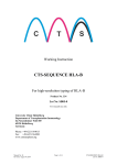
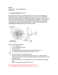
1
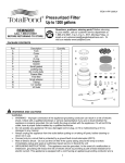
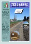
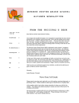
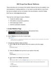
Xenon Chamber
Solutions for Cr ystal Growth
Table of Contents
Xenon Chamber
1 The Xenon Chamber
2
Introduction 2
Xenon 2
What is Included 2
Available Separately 2
Before Getting Started 3
Getting Familiar 4
2
Operating the Xenon Chamber
5
Installation 5
Operation Requirements 6
Pre-Operation 6
Operation 8
Shutting Down the Xenon Chamber
3
Appendix A
10
11
General Information 11
Specifications 11
Recommended Accessories 11
Important Safety Instructions 11
Warning 11
References 12
Service and Support 12
4
Appendix B
13
Tips and Troubleshooting 13
Alignment of the Plunger 13
Alignment of the Chamber Lock 13
Warranty Policy 14
Product Reference Information 14
1
The Xenon Chamber
s e Xenon
c tChamber
i o n
1
Introduction
The Xenon Chamber is a pressure chamber designed to produce xenon derivatives of biological macromolecular crystals.
Typically, isomorphous derivatives are formed by diffusing heavy atoms such as lead or mercury based compounds into the crystal with the anticipation that the heavy atom molecules
will bind in an ordered fashion to each biological macromolecule.
Xenon
Xenon is a noble gas which can bind to specific sites in a biological macromolecule. There
are numerous examples in the literature demonstrating that xenon-macromolecule complexes
can serve as heavy atom derivatives (see page 11). The xenon-macromolecule complex is
obtained by placing the macromolecular crystal under a pressurized xenon atmosphere. The
use of xenon in a pressurized chamber allows one to manipulate the occupancy and binding
of xenon by varying pressure and incubation time.
What is Included
Included in this package are the following:
Quantity (1) Xenon Chamber
Quantity (1) CrystalCap Holder for 1000ml Dewar
Quantity (5) Mini-Vial with Wick
Available Separately
Xenon Chamber Pressure Regulator & Connector - Catalog Number HR4-793
Xenon Recovery System - Catalog Number HR4-797
Mini Vial With Wick 5 Pack - Catalog Number HR4-795
2
Before Getting Started
Operators of the Xenon Chamber should be trained in the use and safety of a pressurized gas
cylinder (xenon gas tank). Please use ANSI/OSHA approved safety goggles and any other
safety equipment recommended by Local, State, and Federal government regulations. Hampton
Research shall not be held liable for any damage resulting from handling or from contact
from said product.
Please read all instructions carefully. This apparatus is only to be used with inert gases. It is
recommended that the Xenon Chamber Pressure Regulator & Connector (Catalog Number:
HR4-793) be used with the Xenon Chamber. Exact fittings cannot be guaranteed with other
pressure regulators. Please refer to operation specifications in Appendix A of the User Manual.
3
Getting Familiar
The illustrations below provides an overview of your Xenon Chamber. Please familiarize
yourself with the Xenon Chamber prior to beginning the installation procedure.
12
13
11
10
16
8
14
7
9
6
15
3
5
4
2
1
18
17
Front View
19
Side View
Legend
1.) Dewar Dock
2.) Chamber Platform
3.) Chamber Pressure Gauge
4.) Slow Release Gas Valve
5.) 3 Way Valve
6.) Xenon Chamber
7.) Chamber Lock
8.) Lock Lever Stop Screw
9.) Lock Lever
10.) Left Guide Stop Screw
11.) Guide Tracks
12.) Guide Track
13.) Plunger Handle
14.) Plunger
15.) Magnetic Base
16.) Right Guide Stop Screw
17.) Safety Shield
18.) Safety Lock
19.) Inlet
4
Operating the Xenon Chamber
s e Xenon
c tChamber
i o n
2
Installation
Tools Required: Crescent Wrench
Prior to installation of the Xenon Pressure Regulator, check to see that the xenon tank valve
is closed, be sure the “Pressure Regulator Valve” is closed, by turning the “T Handle” counter
clockwise, and that the “Black Needle Valve” is closed, by turning it clockwise. Installation
and setup of the Xenon Chamber should be done on a sturdy, flat surface within 20 inches of
the xenon tank.
Regulated Pressure Gauge
Xenon Tank Gauge
Pressure Regulator Valve T Handle
Black Needle Valve
Quick Connector,
Attaches to Xenon
Chamber “Inlet”
Attach to Xenon Gas Tank
Xenon Chamber Pressure Regulator
Step 1: Attach Xenon Chamber Pressure Regulator (Catalog Number: HR4-793) to the xenon
tank. Tighten using a crescent wrench.
Step 2: Attach other end of the “Xenon Chamber Pressure Regulator” to the Xenon Chamber
“Inlet”. Pull back on the quick connector to expose the metal ball bearings. While pulling
back on the quick connector attach to the male inlet on the Xenon Chamber. Attachment
will be confirmed by the quick connector clicking firmly onto the male inlet.
5
Operation Requirements
The following items are necessary for the use of the Xenon Chamber:
1.)
2.)
3.)
4.)
5.)
6.)
Xenon Gas
Liquid Nitrogen
CrystalCap Magnetic/CrystalCap Copper Magnetic
MicroTube & CryoLoop or Mounted CryoLoop
1000ml Dewar
Tweezers
Pre-Operation
Pre-operation is recommended in order to determine the proper setting conditions and for
aligning the dewar on the “Dewar Dock”. This should be done simply using a CryoLoop with
only mother liquor suspended within the CryoLoop, no crystal! Please use ANSI/OSHA
approved safety goggles and any other safety equipment recommended by Local, State, and
Federal government regulations.
Step 1: Obtain a 1000ml Stainless Steel Dewar Flask.
Step 2: Place the CrystalCap Holder inside the Dewar.
Step 3: Place a CrystalCap Vial into the CrystalCap Holder.
Step 4: Set Dewar onto the “Dewar Dock”.
Step 5: Place approximately 100 microliters of mother liquor into a “Mini-Vial with Wick”.
Shake the “Mini-Vial” to allow the mother liquor to absorb into the wick. Add additional
mother liquor as necessary to maintain approximately 2 millimeters of mother liquid in the
“Mini-Vial”.
Step 6: Open “Safety Cover”.
Step 7: Place the “Mini-Vial with Wick” into the “Xenon Chamber”.
Step 8: Raise the “Plunger” and slide it to the right against the “Right Guide Stop Screw” over
the Dewar.
Step 9: Lower the “Plunger” and align the Dewar so that the CrystalCap Magnetic or CrystalCap
Magnetic Copper (here after referred to as “CrystalCap”) aligns flush with the “Magnetic Base”
on the bottom of the “Plunger”.
6
Step 10: Raise the “Plunger” and place the “CrystalCap” onto the “Magnetic Base” of the
“Plunger”.
Step 11: Slide the “Plunger” with the “CrystalCap” to the left against the “Left Guide Stop Screw”
over the “Xenon Chamber”.
Step 12: Lower “Plunger” into the “Xenon Chamber”.
Step 13: Close the “Chamber Lock” completely. The chamber is now sealed and ready to accept
xenon.
Step 14: Close “Safety Shield”.
Step 15: Check to see that all valves in the xenon tank and Xenon Pressure Regulator are
closed.
Step 16: Turn the “3 Point Valve” to the “Apply Pressure” position.
Step 17: Open valve on xenon gas cylinder.
Step 18: Open “Pressure Regulator Valve” by turning the “T Handle” clockwise to a pressure
between 0 and 600 psi.
Step 19: Slowly turn the “Black Needle Valve” counter clockwise to set pressure in the “Xenon
Chamber”. This pressure can be monitored by the “Chamber Pressure Gauge” on the “Chamber
Platform”. Do not allow pressure to go beyond 600 psi. Note: If the pressure of the “Xenon
Chamber” exceeds 600 psi, pressure will vent through the “Safety Valve”.
Step 20: Once the desired pressure has been reached, close (turn clockwise) the “Black Needle
Valve” and turn the “3 Point Valve” to “Hold Pressure”.
Step 21: After one minute turn the “3 Point Valve” to the “Release Pressure” position. It is recommended that pressure be released over a 3 to 5 second period. The at which pressure is
released can be controlled by using the “Slow Release Gas Valve”. Note: Pressure is ONLY
released from the “Xenon Chamber” not from the hose connecting the xenon tank to the
Xenon Chamber.
Step 22: Once pressure has been released open the “Safety Shield”.
Step 23: Open the “Chamber Lock”.
Step 24: Raise the “Plunger” and slide it to the right.
7
Step 25: Lower “Plunger” into the CrystalCap Vial. Raise the “Magnetic Release Lever” and raise
the “Plunger” to leave the “CrystalCap” in the CrystalCap Vial. At this point confirm the alignment of the Dewar and the “CrystalCap” holder with the “Plunger”.
Step 26: Remove the “CrystalCap” and observe the CryoLoop under a microscope.
The proper operation of the Xenon Chamber, that is the speed at which pressure was
increased and decreased, should leave the mother liquor within the CryoLoop. Rapid pressurization and depressurization of the “Xenon Chamber” will cause the mother liquor to blow off
the CryoLoop. Please practice several times prior to the actual use of a crystal.
Note: When repeating the Pre-Operation procedure the hose connecting the xenon tank to the
Xenon Chamber is already primed. Once STEP 16 is reached again turn the “3 Point Valve”
SLOWLY! Pressure will be applied to the “Xenon Chamber” immediately. Please use caution.
Operation
Begin actual operation of the Xenon Chamber only after going through the Pre-Operation set
up.
Note: When beginning the Operation procedure after the Pre-Operation procedure, the hose
connecting the xenon tank to the Xenon Chamber is already primed. Once STEP 8 is reached
turn the “3 Point Valve” SLOWLY! Pressure will be applied to the “Xenon Chamber” immediately. Please use caution.
Step 1: Fill the 1000ml Dewar with liquid nitrogen. Be sure that liquid nitrogen has also been
placed within the CrystalCap Vial.
Step 2: Place approximately 100 microliters of mother liquor into a “Mini-Vial with Wick”.
Shake the “Mini-Vial” to allow the mother liquor to absorb into the wick. Add additional
mother liquor as necessary to maintain approximately 2 millimeters of liquid in the Vial.
Step 3: Open the “Safety Shield”.
Step 4: Place the “Mini-Vial with Wick” into the bottom of the “Xenon Chamber”.
Step 5: Raise the “Plunger” and attach “CrystalCap” with crystal to the “Magnetic Base” of the
“Plunger”.
Step 6: Slide the “Plunger” with the “CrystalCap” to the left against the “Left Guide Stop
Screw” over the “Xenon Chamber”.
Step 7: Lower “Plunger” into the “Xenon Chamber”.
8
Step 8: Close the “Chamber Lock” then close the “Safety Shield”. The chamber is now sealed
and ready to accept xenon.
Step 9: Turn the “3 Point Valve” to the “Apply Pressure” position.
Step 10: Open valve on xenon gas tank to obtain a desired pressure then close valve on xenon
gas tank.
Step 11: Open “Pressure Regulator Valve” to a pressure between 0 and 600 psi.
Step 12: Slowly turn the “Black Needle Valve” to set the desired pressure in the “Xenon
Chamber”. This pressure can be monitored by the “Chamber Pressure Regulator” on the
“Chamber Platform”. Do not allow pressure to go beyond 600 psi.
Step 13: Once the desired pressure has been reached close the “Black Needle Valve” and turn
the “3 Point Valve” to “Hold Pressure”. Monitor the “Chamber Pressure Gauge” during incubation to assure pressure is maintained at the desired level. Incubation time will vary depending upon the protein. Typical incubation time is 15 minutes to 60 minutes.
Step 14: After incubation slowly turn the “3 Point Needle Valve” to the “Release Pressure” position. Pressure will be released at the desired rate as determined in the pre-operation setting
of the “Slow Release Gas Valve”.
Step 15: Once pressure has been released open the “Safety Shield”.
Step 16: Open the “Chamber Lock”.
Step 17: Raise the “Plunger” and slide it to the right over the dewar and CrystalCap Vial containing liquid nitrogen.
Step 18: Lower “Plunger” into the 1000ml Dewar. The “CrystalCap” holding the crystal will be
lowered into the CrystalCap Vial containing liquid nitrogen or liquid propane.
Step 19: Lift the “Magnetic Release Lever”. This will release the “CrystalCap” from the
“Magnetic Base” on the bottom of the “Plunger”. Raise the “Plunger” while lifting the
“Magnetic Release Lever” and slide the “Plunger” away.
The crystal is now derivatized (hopefully!) and frozen, and is now ready for data collection.
9
Shutting Down the Xenon Chamber
Once xenon derivatization has been completed depressurization is required in order to disconnect the xenon tank from the Xenon Chamber.
Step 1: Close the “Tank Valve” on the xenon tank. Close the “Pressure Regulator Valve” by
turning the “T Handle” counter clockwise until it spins freely. Close the “Black Needle Valve”
clockwise until it stops.
Step 2: Set the “3 Point Valve” to “Release Pressure”. Turn the valve to release any pressure in
the “Xenon Chamber”.
Step 3: Open “Chamber Lock”, raise “Plunger”, and slide it to the right away from the “Xenon
Chamber”.
Step 4: Remove the “Mini-Vial with Wick” from the “Xenon Chamber”.
Step 5: Turn the “3 Point Valve” to “Apply Pressure” with the “Xenon Chamber” open. This
will allow any pressure in the hose connecting the xenon tank to the Xenon Chamber to be
released.
Step 6: Slowly open the “Pressure Regulator Valve” by turning the “T Handle” clockwise.
Step 7: Slowly open the “Black Needle Valve” by turning it counter clockwise. This will
release any remaining pressure within the “Xenon Chamber Pressure Regulator” through the
“Xenon Chamber”.
Step 8: Disconnect the “Xenon Chamber Pressure Regulator” from the Xenon Chamber “Inlet”.
Pull back on the quick connector to expose the metal ball bearings. This will cause an automatic release of the quick connector from the male inlet on the Xenon Chamber.
Step 9: Disconnect “Xenon Chamber Pressure Regulator” from the xenon tank.
10
Appendix A
s e Xenon
c tChamber
i o n
3
General Information
• Specifications
Operation Pressure: 0 - 600 psi (0 - 4.1Mpa, 0 - 41 bar)
Pressure Regulator CGA Number: 580
Pressure Regulator Hose Length: 21 inches
• Recommended Accessories
CrystalCap Magnetic, CrystalCap Copper Magnetic
1000 ml Dewar: Catalog Number HR4-699
1000 ml Dewar Cork Cap: Catalog Number HR4-701
Replacement Mini-Vial with Wick: Catalog Number HR4-795
Xenon Chamber Pressure Regulator: Catalog Number: HR4-793
Xenon Recovery System: Catalog Number: HR4-797
Important Safety Instructions
For your own safety and that of your equipment, read and follow all the instructions in this
section. Keep these instructions available for reference by you and others.
Warning
• Use of this equipment requires working with pressurized xenon gas. Only personnel familiar with the use of pressurized xenon gas should handle this device.
• Use ANSI/OSHA approved safety goggles and any other safety equipment recommended by
Local, State, and Federal government regulations.
• Use of the Xenon Chamber requires use of liquid nitrogen. Personnel should also be familiar with the use and handling of liquid nitrogen.
11
References
• Machius, M., Henry, L., Palnitkar, M., Deisenhofer, J., A Xenon Derivative of UvrB Crystal
Prepared Using the Hampton Research Xenon Chamber, (1999) Proc. Natl. Acad. Sci. USA 96,
11717-11722.
• Otwinowski, Z. & Minor, W. (1997) Methods Enzymol. Vol. 276, edited by C.W. Carter, Jr. and
R.M. Sweet. New York: Academic Press.
• Sauer, O., Schmidt, A., Kratky, C. Freeze-trapping isomorphous xenon derivatives of protein
crystals. J. Appl. Cryst. 30, 476.
• Schiltz, M., Fourme, R., Broutin, I., & Prange, T. (1995) Structure 3, 309-316.
• Schitz, M., Prange, T., & Fourme, R. (1994) J. Appl. Cryst. 27, 950-960.
• Schiltz, M., Shepard, W., Fourme, R., Prange, T., De La Fortelle, R., & Bricogne, G. (1997) Acta
Cryst. D53, 78-92.
• Soltis, S.M., Stowell, M.H.B., Wiener, M.C., Phillips, G.N. Jr., & Rees, D.C. (1997) J. Appl. Cryst. 30,
190-194.
• Stowell, M.H.B., Soltis, S.M., Kisker, C., Peters, J.W., Schindelin, H., Rees, D.C., Cascio, D., Beamer, L.,
Hart, P.J., Wiener, M.C., & Whitby, F.G. (1996) J. Appl. Cryst. 29, 608-613.
• Vitali, J., Robbins, A.H., Almo, S.C., & Tilton, R.F. (1991) J. Appl. Cryst. 24, 931-935.
Service and Support
For service and support of the Grease Machine please contact Hampton Research. Please read
and understand the “Warranty Policy” for your Xenon Chamber prior to contacting Hampton
Research.
12
Appendix B
s e Xenon
c tChamber
i o n
4
Tips and Troubleshooting
Alignment of the Plunger:
Plunger alignment can be adjusted by modifying the either the “Left Guide Stop Screw” or
“Right Guide Stop Screw”.
If the “Plunger” does not align properly over the dewar even after trying to reposition the
dewar under the “Plunger”, adjust the “Right Guide Stop Screw” by loosening the nut. Adjust
the “Right Guide Stop Screw” as appropriate and tighten the nut.
If the “Plunger” does not align properly over the “Chamber Lock”, adjust the “Left Guide Stop
Screw” by loosening the nut. Adjust the “Left Guide Stop Screw” as appropriate and tighten
the nut.
Alignment of the Chamber Lock:
If a problem persists where the fins of the “Plunger” do not align properly with the fins of
the “Chamber Lock”, adjust the “Chamber Lock Stop Screw” by loosening the nut. Adjust the
“Chamber Lock Stop Screw” as appropriate and tighten the nut.
13
Warranty Policy
Please complete and return the enclosed warranty validation paper. This is your proof of
purchase and warranty activation. Failure to return the enclosed warranty validation paper
will forego any and all rights to warranty protection and you will be subjected to standard
repair costs of the product in question. If you do not agree with the following terms and conditions please contact Hampton Research Customer Service for return information.
Hampton Research Corp. (hereafter “HR”) warrants for ninety (90) days from date of purchase
by the initial purchaser that this product shall be free of defects in material and workmanship. Any material or workmanship determined defective by HR within the ninety (90) days
shall be repaired or replaced without charge for parts and labor provided the unit is returned
in the original box, and transportation costs prepaid to Hampton Research, 34 Journey, Aliso
Viejo, CA 92656-3317, or to such other service facility authorized by HR. HR shall pay shipping
costs to return the unit to its owner. Products returned for repair must first be approved for
return by Hampton Research. Contact Hampton Research for a Repair Return Authorization
Number. Products returned without a Repair Return Authorization Number will not be
accepted.
This warranty does not cover damage caused by accident, misuse, abuse, neglect, unauthorized
or improperly performed repairs or alterations, and/or wear and tear occasioned by the use
of the product, and does not include any expense for inconvenience or loss of use while the
product is being repaired or replaced.
HR expressly disclaims any liability for consequential damages arising from the sale, use, or
inability to use the product. Any warranty implied by law, including any warranty of merchantability or fitness, is expressly limited to the ninety (90) days warranty term. The foregoing statements of warranty are exclusive and in lieu of all other remedies.
Product Reference Information
Purchase Date:
Invoice Number:
Serial Number:
Please save the following information and have it ready at the time of any questions or concerns regarding the Xenon Chamber.
© 2001-2003 Hampton Research Corp. all rights reserved
Printed in the United States of America. This guide or
parts thereof may not be reproduced in any form without
the written permission of the publishers.
14