1
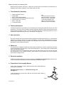
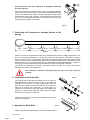
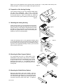
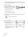
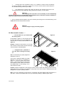
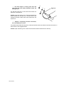
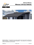
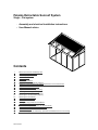
Palazzo Retractable Sunroof System
Single - Flat system
- Assembly and electrical installation instructions
-
User Manual advice
Contents
1.
2.
3.
4.
5.
6.
7.
8.
9.
10.
11.
12.
13.
14.
15.
16.
17.
18.
19.
20.
21.
22.
22.
24.
Before Arrival at the Assembly Site
Tools Needed for Assembly
Fastening Equipment
Noise Insulation
Winter-use
Electrical Installation
Preparation of the Assembly Mounts
Positioning and Fastening the Assembly Mounts to the Greenhouse
Preparation of the Guide Rails
Mounting the Guide Rails
Preparation of the Awning Housing
Mounting the Awning Housing
Mounting the Base Support (Option)
Mounting the Guide Rollers (Option)
Mounting the Drive Belts
Alignment of the Awning
Test-run
Setting the Stop-postions of the Motor
Roof and Tin Cover Sheet
Eletrical Hook-up – Instructions for the Electrician
Operating Instructions for Tubular Motors
Connection Errors
Hazard Warning for the Assembly, Operation and Maintenance of an Awning
What should I do when ……
Stand 10/2005
Before Arrival at the Assembly Site
Please read the assembly instructions. Make sure the awning and all accessories are present and undamaged. Check that the shipping is in accordance with your order.
1. Tools Needed for Assembly
•
•
•
•
•
•
•
Measuring-tape and pencil
Sturdy ladder
Size 2, cross-head screwdriver
Ratchet with extension and sockets size 8 and 10
Allen keys size 2.5, 4, 5 and 6
Motor – Test cable
2 sawhorse trestles
Tip:
To ensure a safe and comfortable work-position on the greenhouse, lay a short, sturdy plank
covered with carpeting on all
sides on both the left and right
sides of the outer covering strip.
2. Fastening Equipment
No fastening equipment is provided by the manufacturers for mounting the guide rails onto the roof of the
greenhouse. The choice of the necessary fastening equipment depends on the chosen assembly mounts
and the mounting conditions on site. If you are unsure about the choice of fastening equipment, consult a
professional in fastening technique such as, for example, the Würth Firm.
3. Noise Insulation
The sound intensity level of this awning is approx. 68 dB (A) according to EN 292-2/A1. If noise insulation
measures are necessary because of on-site circumstances, they should be implemented during the assembly process and based on the consultation of a professional. When in doubt consult a firm or assessor
specialized in noise insulation techniques.
4. Winter-use
The awning may be damaged or destroyed under freezing conditions as a result of ice build-up on the rails
as well as through the pile-up of snow or ice on the awning-canvas. If the awning-canvas is rolled up while
wet it may also freeze together.
The awning should only be operated after assuring that the guide rails are free of ice and snow and that
the awning-canvas is dry. Automatic operation, when present, must be switched over to hand operation
when there is a danger of frost.
5. Electrical Installation
Please ensure that the electrician receives the following “Instructions for the Electrician” (see Point 20.).
To be sure, ask that the handing-over of the instructions be confirmed in writing.
6. Preparation of the Assembly Mounts
Various types of assembly mounts or distancing pieces are included depending
on what you have ordered.
2
Standard assembly mount or standard distancing piece
(see Figure 1):
Loosen the setscrew (1) with a size 4 allen key and pull the clamp cylinder (2)
out of the mount (3).
3
1
Figure 1
Stand 10/2005
3
Assembly mounts with side adjustment or adjustable distancing
piece (see Figure 2):
2
Using a size 6 allen key, screw the cylinder screw (1) through the assembly
mount top piece (2) into the square nut (3). Set all the adjustable distancing
pieces to the desired height. Make sure that the telescopic tubes remain
inserted with at least 20 mm of overlap. The height at which the pieces are
set can vary, but the guide rails along the awning track mustn’t have any
height offset with respect to one another.
1
Figure 2
7. Positioning and Fastening the Assembly Mounts to the
Awning
350 - 800
max. 2000
max. 2000
max. 2000
max. 1500
Figure 3
Fasten the mounts to the greenhouse taking into consideration the pertinent handling instructions for use
of the correct fastening equipment. In the process, ensure that the minimum and maximum measurements, as seen in Figure 3, are respected. The inside micrometer between the left and the right assembly
mount is the same as the ordered-measurement of the awning (see shipping note). Differences in these
measurements can only be corrected up to 20 mm in assembly mounts with side adjustment. Tighten the
screws only to the point where they still allow the distancing piece to be adjusted in the slots.
If the degree of adjustment isn’t sufficient, the awning is either too wide or too narrow and must be
adjusted in the factory by the manufacturer.
Never attempt to shorten the awning yourself; this will, in all cases, nullify the
garantee.
8. Preparation of the Guide Rails
Figure 4
Lay the guide rails on two sawhorse trestles, which you have prepared beforehand. Slide the clamping cylinder (1) as well as the
assembly mount top piece (2), and the guide roller holder (3),
which may be included, into the lower chamber of the guide rail.
Take care to do this in the correct order. If a guide roller is included in the unit, fasten the guide roller holder in the middle of the
guide rails. If several guide rollers are needed, space the holders
evenly over the length of the guide rails.
Loosen the covering tin on the side of the exit baffle with a 2.5 mm
allen key (see Figure 5).
9. Mounting the Guide Rails
Figure 5
Fasten the guide rails to the assembly mounts (see Figures 6 and 7).
Stand 10/2005
Figure 6
Figure 7
1
3
2
Tighten up only the uppermost mount; leave the lower mounts loose. In the process, leave the top end
sticking out approx. 100 mm over the middle of the uppermost mount.
10. Preparation of the Awning Housing
1
2
Lay the awning housing on top of two sawhorse trestles which
you have set up beforehand. With a size 2 cross-head
screwdriver, loosen the fastening screws (1) on the top (2) and
lift it up (see Figure 8). With a 5 mm allen key, loosen the
counter-sunk screws (3) and rosettes (4) for mounting the rails.
1
3 4
Figure 8
11. Mounting the Awning Housing
Lift the awning housing up onto the greenhouse and place it
above the ends of the guide rails (see Figure 9). Then lift the
awning housing up to the height of the guide rails and insert
the studs (1) in the guide rails (2). Screw the housing and
the guide rails together with the counter-sunk screws (3) and
rosettes (4), which you loosened before.
1
3 4
2
Loosen the clamping screw on the uppermost assembly mount
(1) on both sides and move the housing with the guide rails into
its final position at the top (see Figure 10). Re-tighten the clamping screw on the uppermost assembly mounts (1); the rest of the
mounts should remain loose.
Figure 10
1
12. Mounting the Base Support (Option)
1
For awning-widths over 5.50 m a base support, which
corresponds to the height of the mounts, is included.
This should be fastened in the middle part of the housing
so that it rests on one of the covering strips of the
greenhouse (see Figure 11). The fastening plates for
the supports are to be found in the bottom groove of the
housing base.
Figure 11
13. Mounting the Guide Rollers (Option)
Place the guide rollers, which are included, in the preassembled holders and screw them on with the help of a 6
mm socket wrench (see Figure 12). The rollers have been
cut to the exact length. Make sure that the guide rails do
not become bent as a result of the rollers. To adjust for
Stand 10/2005
Figure 9
this, use the available range of side adjustment in the slots of the assembly mounts. If the adjustment
range is insufficient then the awning which you have ordered is either too wide or too narrow and must be
changed in the factory by the awning manufacturer.
Figure 12
14. Mounting the Drive Belts
3
The drive belts are wound in the factory in 5 coils on
the belt spools. The drive belts are shipped as loose
spools together with the rest of the parts. Open the
spools and, following Figure 13, run the drive belts
• over the pulleys in the awning housing (1)
2
1
Figure 13
• through the bottom slot of the guide rails
• around the front pulleys (2)
• and back through the upper slot in the guide rails
• finally, hang them onto the hooks in the carriage (3).
When hanging the belts on the hooks in the carriage it is necessary that the belts are tightened
(pulled) approx. 60 cm.
Warning! Do not twist the drive belts.
15. Alignment of the Awning
It is very important that the guide rails are fixed at
right angles to the awning housing. Check for this
the following way (see Figure 14):
A1
9
•
all A- measurements must be equal
•
both B- measurements (diagonals) must be
equal
•
make sure that the guide rails are straight and
run parallel to one another
tighten up all the fastening screws on the assembly mounts
0
°
A2
B1
B2
A3
16. Test-run
Stand 10/2005
Figure 14
The stop positions of the motor are not set. When running the awning out, make sure that the fasteners for the drive belt loops do not clash with the pulleys on the guide rails! (see indicator note)
a)
Run the awning out and check:
•
Are the drive belts running smoothly through the front pulleys?
If not: Check the awning alignment. (Point 16)
•
Does the awning-canvas lie free of diagonal folds?
If not: Check the awning alignment. (Point 16)
•
Do the drive belts run smoothly on the belt spools?
If not: Check the awning alignment. (Point 16)
b)
Run the awning in and check:
•
Does diagonal folding occur?
If so: Check the awning alignment. (Point 16)
•
Observe whether the built-in free-wheel limit switch in the motor cable switches off.
If not: See Point 19
TIP :
The motor is equipped with an overheating-guard. You can only run the awning
out and in 2 – 3 times. After that, the motor will shut off.
After about 30 minutes it cools off and is ready to be operated again.
17. Setting the Stop-positions of the Motor
The stop-positions of the motor must be set during assembly.
Proceed as follows:
When the awning cover or the revisions cover is open, the set-up buttons are visible. The button furthest forward in the direction of the awning when running it out is the button for the stop-position of the awning when
running it out. The button furthest back is for the stop-position when withdrawing the awning.
Both buttons are engaged by pushing them in.
Outward direction:
The end shaft is run out until the indicator markings on the guide rails and then stopped. By pushing the
forward button again, the stopping-point is remembered by the motor and the button springs out a little.
The stopping-position is now set.
Warning! Never let the end shaft run past the indicator markings! The awningcanvas will stretch after being used for a while. If the stop-position is set incorrectly, the belt fasteners could run into the pulleys and thereby damage the entire awning.
Stand 10/2005
Inward Direction:
When running the awning in, the shut-off occurs through an external end-switch. This happens when the
inward stop-position is reached by way of the roll-course of a carriage. In order that the stop-position is
properly reached, the back set-up button must always remain pushed (engaged).
18. Cover and Tin Cover Sheet
a) Lay the awning-cover on top, so that the grooves on the backside tie into one another. Finally, screw
in the cover fastening screws again.
b) Screw the tin cover sheet into the exit baffles.
19. Electrical Hook-up – Instructions for the Electrician
Warning!
Awnings are not portable devices and must be operated by means of a fixed electrical connection.
Electrical installation work on a 230 V power supply may only be carried out by accredited specialists!
When installing the electrical connection, the applicable VDE-Guidelines and the regulations of the
energy company in your area must be followed. During installation, the possibility of an all-pole
separation from the power supply must be created using, for example, a Hirschmann connector, a
dipolar sunblind switch with a minimum of a 3 mm contact opening, or an all-pole main switch. The
‘in’ and ‘out’ commands must exclude each other. During change in the direction of rotation, the
drive must be idle for at least 0.5 sec.
When these instructions are not followed, when the electrical connection is not carried out properly according to DIN, or when the recognized technical rules are ignored, neither the motor nor awning manufacturers are responsible for material damage or personal injury (see Figure 15):
Stand 10/2005
•
Never connect more than one motor to a single-pole switch!
•
Only by using group control can more than one motor be operated by a single
switch.
•
Switches for the awning motors must be electrically and mechanically controlled.
•
Lay the motor cables such that water drops do not run down the cable into the
motor (droplet kink).
Figure 15
21. Operating Instructions for Tubular Motors
Warning!
NOT all plug-in motors are necessarily the same as other common household
electrical devices! It is essential that you pay careful attention to the following
operating instructions.
a) Never activate motors in parallel.
b) Never run motors with the ‘in’ and ‘out’ switches activated at the same time.
c) Ensure a switch pause between ‘in’ and ‘out’ commands of approx. 0.5 seconds.
22. Connection Errors
The most common causes for the overloading of limit switches are explained below in order to prevent defects in the micro-switches.
a. Parallel connection of two or more drives
Drives connected in parallel never have exactly the same running time. Therefore, the drive that is
shut off first receives an inductive and capacitative tension in the opposite direction from the drive that
is still running. This reverse tension, which can be up to 1,000 volts, sets the shut off drive in motion in
the opposite direction until it receives system tension again from the limit switch and begins to run
again in the opposite direction. This pendulum motion continues until all parallel-connected drives
reach their stop positions. Each time the drives are shut off in this fashion the limit switch is overloaded and damaged (see also Point ‘c’, ‘Switch-pause too short’). Furthermore, this often results,
Stand 10/2005
apart from the pendulum motion, in an altered stop position for the awning. In extreme cases, the limit
switches become permanently fused which causes the continuous activation of the motor.
b.
Simultaneous ‘in’ and ‘out’ signals
Through the use of switches which aren’t mutually exclusive or the installation of various non-exclusive
switch positions, the simultaneous activation of the ‘in’ and ‘out’ directions can occur. This is not allowable since the limit switch contacts will be overloaded as a result of reverse induction that occurs in the
motor coils. The resulting damage is similar to that described in Point ‘a’.
c. Switch-pause too short
In some installations it was determined that the switch pause between ‘in’ and ‘out’ signals was not
sufficient. The control must have a switch pause of approx. 0.5 seconds when switching running
directions. This is needed to ensure that the mechanical drive comes to a complete stop and that the
induction tension in the motor and the charge in the capacitor wear off. If a drive is switched over too
quickly, extremely high currents result briefly which damage the contacts of the controlling relays –
and sometimes only momentarily – they fuse. This leads to the simultaneous activation of both
operating directions. As a result, the micro-switches in the drive become damaged (see Point ‘b’).
Failures of this type occur often especially in programmable units (SPS, EIB) or in self-designed relay
switches.
All of the problems caused by the effects described above usually occur after a certain operating time
since the limit switches can only withstand the strain a few times. All these effects are taken into consideration in the controls or switches that come with the unit.
23. Hazard Warning for the Assembly, Operation and Maintenance of an Awning
Awnings set-up outside are subjected to strong external forces resulting from weather influences (eg. wind factors, weight-loads from rain and snow).
Follow the assembly instructions carefully during assembly. It is advisable to allow a specialist to carry out the assembly.
•
Make sure of the stability and design of the surface on which you are assembling. It must be
able to accept the forces imposed upon it by the operation of the awning.
•
Electrical connections may only be installed by an authorised electrical specialist and taking
into consideration the applicable VDE-guidelines and the regulations of the on-site energy supply firm.
•
Awnings operated by electrical motors with mounting heights of less than 2.5 m must be
controlled by way of a non-locking button in plain view. The possibility of someone reaching into
moving parts must be excluded during operation.
Warning!
There is a danger of injuries resulting from crushing or clamping!
•
With wind-forces above 5 (8 to 11 m/s wind speed - large branches move) the awning
must be withdrawn! Damage to the awning could occur.
•
Awnings are not rain-protection devices. Operation during light drizzles is, however, possible.
The canvas must have a slope of at least 15°. The water must run off, a water skin build-up is not
allowable (damage through high water weights is possible).
An awning-canvas that has been rolled up wet must be rolled out and allowed to dry as soon as
possible (mould build-up, water stains).
Stand 10/2005
•
Awnings must not be operated in snowy or icy conditions. A frozen canvas can damage
the awning! Therefore, when there is danger of ice or snow, use the manual control rather than
the automatic awning control for your safety!
•
For maintenance or cleaning and repair jobs (service), the electrical drive must be disconnected from the power supply (eg. safety, Hirschmann connector, or main switch).
Warning!
Even awnings that have been run out manually can be automatically
switched on by means of a wind-watcher (wind activated sensor). Therefore to prevent accidents always ensure disconnection from the power supply.
• No long objects should be placed in the area covered by the awning since an activated awning could
collide with them and cause them to fall over.
Warning!
There is a danger of injury from falling objects.
24. What should I do when……
…… the end shaft runs up crooked under
the awning cover?
Figure 16
As portrayed in Figure 16, the end shaft runs too
far under the awning cover on the right side. The
cause of this is an overly loose belt tension on the
right side.
Solution: increase the belt tension on the right
side. Unhook the drive belt and set the belt-length
100 mm shorter on the belt fastener.
…… a diagonal fold is produced on
one side while running the awning
in?
Figure 17
Make sure the awning is properly aligned as
described in Point 16.
If this fold is produced despite the proper
alignment of the awning, as displayed in
Figure 17, it may be a result of the canvas
tension. Awning canvasses are cloths sewn
from webbing in which, either as a result of
the webbing itself or of the sewing, an uneven tension can result.
Solution: Change the alignment of the awning to suit the canvas. Loosen the clamping screws of the opposite guide rail, on the right in the diagram, and pull the rail a few mm down. Observe that the fold
disappears or becomes noticeably smaller.
Note: It can occur (especially in large SOLTIS –canvasses), that small diagonal folds are produced on
both sides. These are unavoidable and can only be reduced by building in additional guide rollers.
Stand 10/2005
…… the motor keeps on running even when the
end shaft has been totally withdrawn under the
awning cover?
Figure 18
The little limit stop lever of the external limit switch has
been bent or has fallen off.
Solution. Open the awning cover. Check the external limit
switch screwed into the side cap. The back roller of the
carriage must make contact with the limit switch lever and
switch it off.
…… despite a functioning electrical connection,
the end shaft doesn’t move?
It is possible that the little limit stop lever of the external limit switch has seized or has been bent and as a
result is stuck in the engaged position.
Solution. Open the awning cover. Check the external limit switch screwed into the side cap.
Stand 10/2005