1
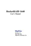
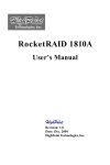
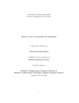
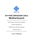
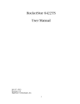
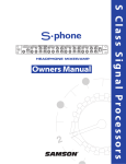
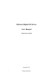
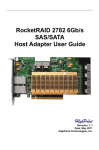
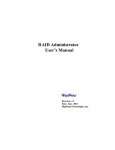
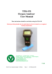
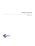
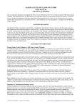
RocketRAID 1520
User’s Manual
Revision: 1.1
Date: Jun. 2002
HighPoint Technologies, Inc.
Notice
Reasonable effort has been made to ensure that the information in this manual is
accurate. HighPoint assumes no liability for technical inaccuracies, typographical, or
other errors contained herein.
Trademarks
Companies and products mentioned in this manual are for identification purpose only.
Product names or brand names appearing in this manual may or may not be registered
trademarks or copyrights of their respective owners. Backup your important data before using HighPoint’s products and use at your own risks. In no event shall HighPoint
be liable for any loss of profits, or for direct, indirect, special, incidental or consequential damages arising from any defect or error in HighPoint’s products or manuals.
Information in this manual is subject to change without notice and does not represent
a commitment on the part of HighPoint.
Copyright
Copyright © 2002 HighPoint Technologies, Inc.. This document contains materials
protected by International Copyright Laws. All rights reserved. No part of this manual
may be reproduced, transmitted or transcribed in any form and for any purpose without
the express written permission of HighPoint.
Table of Contents
Table of Contents
Chapter 1
Introduction
Serial ATA Overview ................................................................................ 1-1
RAID Basics ............................................................................................. 1-1
RocketRAID 1520 ...................................................................................... 1-2
RocketHead 100 ........................................................................................ 1-4
Chapter 2
Adapter Installation
Adapter Layout ......................................................................................... 2-1
Hard Disk Connection ............................................................................... 2-1
Adapter Installation .................................................................................. 2-1
Adapter’s Installation Verification ............................................................ 2-2
Driver Installation ..................................................................................... 2-3
Chapter 3
BIOS Configuration
Enter BIOS Configuration Utility .............................................................. 3-1
Create Disk Array ...................................................................................... 3-1
Delete Disk Array ...................................................................................... 3-4
Set Boot Device ........................................................................................ 3-5
Duplicate Critical RAID 1 array ................................................................. 3-6
Rebuild Broken RAID 1 array .................................................................... 3-6
Chapter 4
RAID Administrator
Installation ................................................................................................ 4-1
Getting Start .............................................................................................. 4-1
Configuration Functions ........................................................................... 4-3
i
Table of Contents
Management Functions ............................................................................ 4-7
View Information ....................................................................................... 4-8
Rebuild Broken RAID 1 array .................................................................... 4-12
Chapter 5
Trouble Shooting
Appendix A
Glossary
Appendix B
Contact Technical Support
ii
Chapter 1
Introduction
This chapter will give a brief introduction on the RAID-related Serial ATA
background knowledge, as well as a brief introduction on RocketRAID
1520 Serial ATA RAID solution.
Contents of this Chapter:
1.1 Serial ATA Overview
1.2 RAID Basics
1.3 RocketRAID 1520
1.4 RocketHead 100
Introduction
1.1 Serial ATA Overview
Serial ATA is a high performance interface for IDE storage devices, and is the evolutionary replacement for the longstanding ATA physical storage interface. It is a practical add-on solution that is compatible with today's leading operating systems, and
can be utilized alongside the existing PC architecture without the need for physical
modification. Serial ATA is scalable and will allow for future enhancements of the
computing platform. Serial ATA's efficient design further simplifies system integration.
The smaller cables and connectors, improved silicon design, and lower voltage requirements alleviate many shortcomings of the current ATA specifications. The thin Serial
ATA cables also significantly improve airflow within a computer's chassis - this helps
combat the risk of damage to vital PC components due to excessive heat retention.
Benefits
. Performance increases to 1.5Gb/s
· Thin cables for easy routing and improved cooling inside a computer chassis
· Reduced pin count enables RAID scalability
· Backward compatible with existing ATA software and drivers
Due to the high rate of performance/cost and character/cost, Serial ATA RAID will be
widely accepted by the market as cost-effective RAID solution, and Rocket RAID 1520
is one of the best Serial ATA RAID solutions.
1.2 RAID Basics
RAID (Redundant Array of Independent Disks) is a method of combining several hard
disks (physical disks) into one logical unit (logical disk). Such combination can offer
either fault tolerance or higher data throughput than a single hard disk system.
There are hard disks can be combined together. The different methods referred as
different RAID Levels, and different RAID levels represent different performance levels,
security levels and implementation costs.
The most frequently used RAID levels include RAID 0, 1 and 5. Also there are some for
example, RAID 0/1 is the combination of RAID 0 and RAID 1. Here is a brief table of
these popular RAID types:
1-1
Introduction
Description
M inimum #
of Drivers
RAID 0
Data Stripting
2
Highest Performance
without data protection
RAID 1
Disk Mirroring
2
Data protection through
100% data duplication
RAID 0/1
Data Striping
and Mirroring
4
Highest performance
with data protection
2
No data protection and
performance improving
but full usage of disk
capacity
JBOD
Disk Spanning
Benefits
1.3 RocketRAID 1520
RocketRAID 15xx is a series of Serial ATA RAID solution contributed by HighPoint
Technologies, Inc., and it mainly consists of two parts: the RAID adapter and the RAID
management software.
RocketRAID 1520 adapter with HPT372A chip as RAID controller is a 2-channel Serial
ATA RAID solution. Serial ATA RAID Management software is a Windows-based
software utility with graphical user interface, and provides users an easy-operation
software tool to configure and manage disks or disk arrays connected to RocketRAID
1520 adapter.
Below are the main features and benefits of RocketRAID 1520:
(1) IDE hard disk collectible. (Supports ATA100/ATA133 hard disk only).
(2) Supports higher data transfer rate up to 1.5Gb/s
(3) Dual independent Serial ATA channels and 2 hard disks allowed connection
(4) Better connectivity (low pin count, small cable and connector)
(5) Thin cable for easy routing and improving computer chassis cooling circulation
(6) RocketHead converter is easy plug and play for all IDE hard disks
(7) Supports RAID 0, 1, and JBOD
(8) Bootable disk or disk array support
(9) Supports OSs like: Windows9x/ME/NT4.0/2K/XP, Linux (Red Hat, SuSE, Turbo,
Caldera), FreeBSD
1-2
Introduction
(10) Windows-based RAID configuration & management software tool (compatible
with BIOS)
(11) Real-time monitoring of device status and error alarm with popup message box and
beeping
(12) Event log for easy troubleshooting
Serial ATA RAID Function and High Performance
It provides multi level RAID supports including RAID 0, 1, and JBOD, as well as
powerful software management functions. RocketRAID 1520 Serial ATA RAID
controller’s performance increases to 1.5Gb/s.
Thin Cable Is Easy Routing And Improving Cooling Condition
Inside A Computer Chassis
The Serial ATA architecture replaces the wide ATA ribbon cable with a thin, flexible
cable that is up to 1 meter in length. The serial cable is smaller and easier to route inside
the computer chassis. The small diameter cable can help to improve airflow inside the
computer system chassis, in such a way to reduce the thermal in the computer.
1-3
Introduction
IDE Hard Disk Compatible
As a 2-channel Serial ATA RAID controller, RocketRAID 1520 is not only able to
connect with Serial ATA hard disk, but also able to connect with IDE hard disk through
RocketHead 100 converter.
1.4 RocketHead 100 (RH100)
RocketHead 100 is an ATA hard disk converter. It is a sophisticate design circuit
board. RocketRAID 1520 Serial ATA controller card can be connected with any of
ATA hard disks simply through RH100 with thin cable. See the picture below:
Note: If users use the regular IDE hard disks instead the Serial ATA hard disk, by
using RocketHead 100 converter connect to RocketRAID 1520, please make sure
that the hard disk jumper must correctly set to master position setting. ( Usually, IDE
jumper default setting is cable select).
RocketHead 100 converter supports ATA100 / ATA133 hard disk only.
1-4
Chapter 2
Adapter Installation
This chapter will tell you how to install RocketRAID 1520 adapter onto your
computer and connect hard disks to the adapter correctly. Please make sure to
read this chapter carefully before starting your installation procedures.
Contents of this Chapter:
2.1 Adapter Layout
2.2 Hard Disk Connection
2.3 Adapter Installation
2.4 Adapter’s Installation Verification
2.5 Driver Installation
If you have any question during installation, please contact our technical support.
Adapter Installation
2.1 Adapter Layout
Adapter
LEDs connection:
The 4-pins LED connector is for LED connecting. From the top to the bottom there are
4 pins, 1-2 for Serial ATA channel1, 3-4 for Serial ATA channel2.
2.2 Hard Disk Connection
We suggest the following connection way depending on disk numbers:
1) If you have only one disk, connect to Serial ATA channel1
2) If you have two disks, connect to Serial ATA channel1, and then SATA channel2 in order
2.3 Adapter Installation
2-1
Adapter Installation
Follow these steps to install the RAID adapter and connect hard disks to the adapter:
1. Shut down the computer and unplugs the power supply;
2. Please discharge static electricity from your body by touching a conductor;
3. Remove the corresponding card bracket from the back of the computer chassis;
4. Insert the RocketRAID 1520 adapter steadily into a PCI slot on motherboard and
then settle with a screw (see picture2);
5. Set jumper of IDE hard disks to master position and settle them inside the computer
chassis (If IDE HDDs are used);
6. Connect Serial ATA hard disk to RAID adapter with Serial ATA cable; If IDE hard
disks are used, then connect the cable and IDE hard disks by using RocketHead100
(see picture3);
7. Connect all power supply connectors to hard disks;
8. Replace the cover of computer chassis.
Note:
1. If adapter or hard disk is not recognized, please refer to Trouble Shooting chapter for
how to solve the problem.
2.4 Adapter’s Installation Verification
After installed RocketRAID 1520 adapter and connected hard disks as required above,
now user can turn on the computer. Please pay attention to the screen display while
starting computer. If the following information appears, it indicates that the RocketRAID
1520 adapter has been successfully installed and recognized by the computer.
2-2
Adapter Installation
Next, RocketRAID 1520 adapter’s BIOS will scan the connected hard disks. Please pay
attention to the screen display (See next page screen shot). If all connected hard disks
are correctly detected, it indicates that all the hard disks have been connected correctly
and recognized by the computer.
2.5 Driver Installation
After the RocketRAID 1520 adapter is installed and recognized by computer, user can
start to install driver.
Windows 9x/ME
After Windows 9x/ME is start-up, Windows system will automatically find the newly
installed adapter and prompt user to install its driver. Follow these steps to install the
driver:
1. After the Add New Hardware Wizard window appears, press Next button until the
following window appears:
2. Insert the driver diskette, then select the Specify a location item and type in the
driver location: A:\Win9x_ME, then click on Next button to continue; (If users install
driver from CD make sure input the correct path, for exampleD: \RRxxxx\Windows\
Driver\Win9x_ME)
2-3
Adapter Installation
3. Confirm the following dialogue windows, and restart the computer when the system
prompts user to restart;
4. After rebooting, Windows will automatically find HighPoint RCM Device and install
its drivers.
Installation Verification
After the driver installation finished and the computer restarted:
1. Right-click on My Computer icon on desktop, and then select Properties item from
the menu;
2. From the popup window, activate Device Manager item, see below:
If there are the two device items under SCSI Controllers tree as shown above, it indicates that the driver has been installed correctly.
If user cannot find these two device items, or there is ? or ! markings on device icon, it
indicates that the driver has not been correctly installed and user need to delete the
devices and reinstall them.
Note:
If user do not restart the computer after installation, then there may have ! on the device
items. User only need to reboot to make the devices normal.
Windows NT4.0
Install driver under existing Windows NT4.0
1. Click Start—>Settings—>Control Panel, then double-click on the SCSI Adapters
icon;
2. Within the follow-up window, select Driver item, then click on Add button;
2-4
Adapter Installation
3. Within the follow-up window, click on Have Disk... button, the following window will
appear, see below;
4. Insert the driver diskette, and type in the path of driver location: A :\Win_NT in the
above window, then click OK; (If users install driver from CD make sure to input the
correct path, for example D:\RRxxxx\Windows\Driver\Win_NT)
5. Within the follow-up window, select HPT372A UDMA/ATA133 RAID Controller
item, and then click OK;
6. Confirm the follow-up system prompts to finish the driver installation. When installation finished, restart the computer.
Install driver during WindowsNT4.0 installation
(Recommend users copy the driver to a floppy diskette's root directory)
1. Press F6 key when the installation program prompts Setup is inspecting your
computer’s hardware configuration;
2. The installation will continue. When installation program prompt user to press S key
to specify other devices, then please press S key;
3. Within the follow-up device type window, select Other, then press ENTER;
4. Installation program will ask user to insert the driver diskette. Please insert the driver
diskette and then press ENTER;
5. Within the follow-up window, select HPT370/372/372A UDMA/ATA133 RAID Controller for WinNT4.0, then press ENTER;
6. The follow-up window will list a set of devices to be installed, in which HPT370/372/
372A UDMA/ATA133 RAID Controller item should be included (If user want to install
other devices, please operate at this time. If all devices have been installed, please go
to next step);
7. Press ENTER to confirm the devices to be installed and continue the installation of
Windows NT4.0.
Installation Verification
After the driver has been installed and the computer is restarted:
1. Click Start—>Settings—>Control Panel, and then double-click on SCSI Adapters
icon;
2. Within the SCSI Adapters window, see below:
2-5
Adapter Installation
If there is HPT372A UDMA/ATA133 RAID Controller item, it indicates that the driver
has been installed successfully.
Windows 2000
Install driver under existing Windows 2000
After Windows 2000 is start-up, Windows system will automatically find the newly
installed adapter and ask user to install its driver. Please follow these steps to install the
driver:
1. When the Found New Hardware Wizard window appears, click Next button to
continue, in the follow-up window, please select Display a list ... and then click Next to
continue;
2. In the follow-up window, select SCSI and RAID Controllers and then click Next to
continue;
3. In the follow up window, click Have Disk..., then Insert the driver diskette and type in
the driver location: A:\Win_2000, then click OK to continue;(If users install driver from
CD make sure input the correct path, for example D:\RRxxxxWindows\Driver\Win_2000)
2-6
Adapter Installation
4. In the follow-up window, select HPT372A UDMA/ATA133 RAID Controller, then
click Next to continue;
5. Confirm the follow up windows and click the Finish button to continue;
6. Next, Windows will find HighPoint RCM device, please confirm the Digital Signature
Not Found window when it appears, when finished, please restart the computer;
Install driver during Windows 2000 installation
(Recommend users copy the driver to a floppy diskette’s root directory)
1. Booting from CD-ROM, when the Windows 2000 Setup blue screen appears and asks
user to Press F6 if you need to install a third part SCSI or RAID driver, please press F6
key;
2. The setup program will continue, later when the setup program asks user if to specify
additional adapters, please press S key;
3. Then the setup program will prompt user to insert the driver diskette. Please insert
the driver diskette, and then press ENTER to continue;
4. The follow-up window will list out the installation choices, please select HPT370/
372/372A UDMA/ATA133 RAID Controller for Windows 2000 and press ENTER to
continue;
5. The follow-up window will list out the devices to be installed, in which HPT370/372/
372A UDMA/ATA133 RAID Controller item should be included; (If user want to install
other devices, please operate at this time. If all devices have been successfully installed,
please go to next step.)
Installation Verification
After the driver has been installed and the computer restarted:
1. Right-click My Computer icon, then select Properties item from the popup menu;
2. In the popup window, select Hardware item and then click Device Manager button.
2-7
Adapter Installation
If HPT372A UDMA/ATA133 RAID Controller and HighPoint RCM Device items exist
in the popup Device Manager window (see above), it indicates that the driver has been
installed successfully. Otherwise, if user cannot find these two device items, or there is
? or ! marks on device icon, it indicates that the driver has not been correctly installed
and user needs to delete the devices and reinstall them.
Windows XP
Install driver under existing Windows XP
After Windows XP is start-up, Windows system will automatically find the newly
installed adapter and ask user to install its driver. Please follow these steps to install the
driver:
1. When the Found New Hardware Wizard window appears, select Install from a list or
specify location (Advanced), and click Next to continue;
2. In the follow-up window, please select Don’t search, I will choose the driver to
install, then click Next to continue;
3. In the follow-up window of device list, please select SCSI and RAID controllers, and
then click Next to continue;
4. In the next window, click on Have Disk..., then type in the driver location: A:\Win_XP
into the follow-up window, then click OK to continue;(If users install driver from CD
make sure input the correct path, for example D:\RRxxxx\Windows\Driver\Win_XP)
5. In the follow-up window, select HPT372A UDMA/ATA133 RAID Controller, then
click Next to continue;
6. In the follow-up window, click on Continue Anyway, then click Finish in the followup window;
7. Next, Windows will find HighPoint RCM device, please confirm the Digital Signature
Not Found window when it appears, when finished, please restart the computer.
2-8
Adapter Installation
Install driver during Windows XP installation
(Recommend users copy the driver to a floppy diskette’s root directory)
1. Booting from CD-ROM, when the Windows XP Setup blue screen appears and asks
user to press F6 key to install third party SCSI or RAID driver, please press F6 Key.
2. The setup program will continue, later when the setup program asks user if to specify
additional adapters, please press S key;
3. Then the setup program will prompt user to insert the driver diskette. Please insert
the driver diskette, and then press ENTER to continue;
4. The follow-up window will list out the installation choices, please select HPT370/
372/372A UDMA/ATA133 RAID Controller for Windows XP and press ENTER to
continue;
5. The follow-up window will list a set of devices to be installed, in which HPT370/372/
372A UDMA/ATA133 RAID Controller item should be included; (If user want to install
other devices, please operate at this time. If all devices have been successfully installed,
please go to next step.)
Installation Verification
After the driver has been installed and the computer restarted:
1. Right-click My Computer icon, then select Properties item from the popup menu;
2. In the popup window, select Hardware tab and then click Device Manager button.
If HPT372A UDMA/ATA133 RAID Controller and HighPoint RCM Device items exist
in the popup Device Manager window (see above), it indicates that the driver has been
installed successfully. Otherwise, if user cannot find these two device items,it indicates that the driver has not been correctly installed and user need to delete the devices and reinstall them.
2-9
Chapter 3
BIOS Configuration Utility
RocketRAID 1520 provided on-card BIOS configuration utility, through
which, user can configure and manage disks or disk arrays connected to
RocketRAID 1520 adapter. BIOS configuration utility is especially useful
when user wants to create a disk array before an OS is installed.
Contents of this Chapter:
3.1 Enter BIOS Configuration Utility
3.2 Create Disk Array
3.3 Delete Disk Array
3.4 Set Boot Device
3.5 Duplicate Critical RAID 1 array
3.6 Rebuild Broken RAID 1 array
BIOS Configuration Utility
3.1 Enter BIOS Configuration Utility
When the following information appears on screen during the computer is starting,
press CTRL+H key to enter BIOS configuration utility.
The main interface of BIOS configuration utility is as below:
Main Menu: This column lists all currently available operation commands.
Help: This column gives help information about the current selected item and
the prompt on available operations.
Status: This column lists all the hard disks and disk arrays connected to the
adapter. When this column is activated, user can select the target device
to perform a specific operation.
3.2 Create Disk Array
Follow these steps to create a disk array:
1. Within the Menu column of main interface, use the arrow key to highlight the Create
Array command and press ENTER to call out the list of creation steps:
3-1
BIOS Configuration Utility
2. Highlight the Array Mode and press ENTER, then a list of array modes will appear, see
below:
Just highlight the target array mode that you want to create, and then press ENTER to
confirm the selection;
If user selected RAID 1 (mirror) array, then an option list will popup to enable user
selecting Duplication or Create Only. Duplication will let BIOS reserve the data on
source disk (the first selected disk) and copy them onto the mirror disk (the second
selected disk) when creating mirror array;
(Creation steps may be different depending on what array mode has been selected)
3. Within the Menu column of main interface, use the arrow key to highlight the Array
Name, and then press ENTER. Then the array name dialogue box will appear, see below:
Just type in the name that you want to name the array, and then press ENTER to
continue;
3-2
BIOS Configuration Utility
4. Within the Menu column of main interface, use the arrow key to highlight the Select
Disk Drives and press ENTER, the Status column will be activated, see below:
Just highlight the target disks that you want to use and press ENTER to select them
respectively; After all disks have been selected, press ESC to go back to the creation
steps menu;
5. If user selected a RAID 0 array in step 2, then now, user needs to select a block size
for the array. Within the Menu column of main interface, use the arrow key to highlight
the Block Size and press ENTER, then select a block size from the popup list, see below;
6. Within the Menu column of main interface, use the arrow key to highlight the Start
Creation Process and press ENTER, then some warning messages will appear, see
below:
Please pay attention to the warning message, and then press Y to finish the creation, or
press N to cancel the creation.
3-3
BIOS Configuration Utility
(The warning message may be different depending on what array mode that user is
creating)
Warning:
Please pay attention to the warning message at Step 6: Creating RAID 0 array, JBOD
array will destroy all data on all the selected disks. When creating mirror array,
Duplication operation will reserve the data on source disk (the first selected disk)
and copy them onto the mirror disk (the second selected disk) when creating mirror
array.
3.3 Delete Disk Array
Follow these steps to delete a disk array:
1. Within the Menu column of main interface, use the arrow key to highlight Delete
Array item, and then press ENTER, then the Status column will be activated, see below:
Highlight the target disk array and then press ENTER to delete it;
(User can select a disk array by selecting its first member disk)
2. Then a warning message will appear as below:
Pay attention to the warning message, and then press Y to delete the selected disk
array, or press N to cancel.
3-4
BIOS Configuration Utility
3.4 Set Boot Device
Follow these steps to select a disk or disk array as boot device:
1. Within the Menu column of main interface, use the arrow key to highlight Select Boot
Disk item, and then press ENTER; the Status column will be activated, see below:
Just use the arrow key to highlight the target disk or disk array, and then press ENTER
to select it as boot device. If user selects a disk or disk array that has a boot mark and
press ENTER, then its boot setting will be canceled.
2. After the disk or disk array is selected, its status will be marked as BOOT, see below:
3-5
BIOS Configuration Utility
3.5 Duplicate Critical RAID 1 array
When booting computer, if BIOS detected a RAID 1 duplication has been canceled or
any reasons that may cause the inconsistency between user data and backup data on
the disk array, then the disk array will be marked as critical status, and BIOS will
automatically prompt user to duplicate the RAID 1 to make the backup data consist
with the user data again, see below:
Just select Duplicate Now to duplicate, or select Continue to Boot to skip. If user
selects Continue to Boot, user still can duplicate the array after booting into the OS.
3.6 Rebuild Broken RAID 1 array
When booting the computer, if BIOS detected one member disk of RAID 1 array is
failed, the array will be marked as broken status. If BIOS detected a RAID 1 array is
broken, and there RAID 1 array and then replace data to the target disk, see below:
3-6
BIOS Configuration Utility
If BIOS detects a RAID 1 array is broken, but no spare disk can be used to rebuild, then
BIOS will prompt users with a few operations to solve the problem, see below:
3-7
BIOS Configuration Utility
1. Power off and replace the failed drive
This command enables user to power off the computer and replace the failed disk with
a good one. If your computer does not support APM, you must turn off your computer
manually. After replacement, user can boot into BIOS and select the 3. Choose replacement drive and rebuild to rebuild the broken array.
2. Destroy the mirroring relationship
This command enables user to cancel the broken array’s data mirroring relationship.
For broken RAID 1 array, the data on the remained normal disk will be reserved after the
destroy operation.
3. Choose replacement drive and rebuild
This command enables user to select an already-connected disk to rebuild the broken
array and replace the data to that disk.
1. After chosen this command line, the Status column will be activated, see below:
Just highlight the target disk and press ENTER to select it;
2. Then the warning message will appear, see below:
3-8
BIOS Configuration Utility
Please pay much attention to the warning message, and then press Y to use that disk to
rebuild, or press N to cancel. If user presses Y, then all the data on the entire selected
disk will be destroyed;
3. Next, BIOS will replace data onto the newly added disk, see below:
User can press ESC to cancel the duplicating process at anytime.
4. Continue to Boot
This command will let BIOS to skip the problem and boot into OS.
3-9
Chapter 4
ATA RAID Software
This chapter introduces for using HighPoint Serial ATA RAID Management software in detail.
Contents of this chapter:
4.1 Installation
4.2 Getting Start
4.3 Configuration Functions
4.4 Management Functions
4.5 View Information
4.6 Rebuild Broken RAID 1 Array
ATA RAID Software
4.1 Installation
Follow these steps to install the Serial ATA RAID software:
1. Browse the software installation CD, and double click on the setup.exe file to begin
the software installation, (if user installs the software from CD-ROM please select the
correct path, for example, D:\RRxxxx\Windows\GUI\ setup.exe);
2. Confirm the follow-up dialoge windows to finish the installation;
3. When installation completed, restart the computer.
With the default option, the setup program will create program group: Start—>Program- >HighPoint. This program group contains the following items:
HighPoint Serial ATA RAID Management software
Read Me
Uninstall...
Main Program
Software Information
Uninstall the Program
4.2 Getting Start
After installed Seral ATA RAID software, it will be automatically started every time
when your Windows OS is started, and the small icon “
” will appear in the tray of
the task bar in the status area to indicate that Serial ATA RAID software is currently
running:
Just double click on the small icon to call out the main interface of the software:
4-1
ATA RAID Software
The main interface has five tabs: File, Configuration, Management, View and Help. You
can switch to different tabs by clicking on it.
File: This tab displays welcome information. Click the Exit button to exit
Serial ATA RAID software.
Configuration: This tab includes four sub-tabs, they are: Create RAID, Delete RAID,
Spare Pool Management and Duplicate. These sub-tabs will be introduced later.
Management: This tab includes two sub-tabs: Event Notification and Refresh. The
Event Notification enables users to set automatic email notification
when specified events occur. When user clicks the Refresh sub tab, the
software will rescan the devices that connected to the adapter, and the
screen will jump directly to the View tab.
View: This screen includes three sub-tabs: System View, Event View and Icon
View. The System View screen will display all disks and arrays connection status. The Event View window will list all the recorded events
during the software are running. The Icon View window will show the
meaning of different icons in the software.
Help: This tab contains the help information for this software.
4-2
ATA RAID Software
4.3 Configuration Functions
Create Disk Array
Follow these steps to create a disk array:
1. Click the tab Configuration —> Create RAID, the folowing window will appear:
Within this interface:
Array Type: This drop-down box enables the user to select disk array type. There
are three array types that the user can select: RAID 0, RAID 1, and
JBOD.
Array Name: User can type in a name for identifying the array to be created. A good
name will make it easy to distinguish different arrays.
Block Size: If user selected RAID 0 array in the Array Type box, then the Block
Size selection drop-down box will be enabled and user must select a
block size here. If user selected RAID 1 or JBOD, then the Block Size
selection dropdown box will become disable.
Available Disks: This pane will list out all the disks that currently can be used to create
disk array.
Selected Disks: This pane will list out the disks that have been selected to create the
disk array. User can highlight the specific disk in Available Disks pane
and click the corresponding hand icon to select that disk into the
Selected Disks pane with no data on it.
4-3
ATA RAID Software
Creation Option: This option is only available after user selects RAID 1 array in the
Array Type box. Duplicate means reserve the data on the source disk
(first selected disk) when creating RAID 1 array. Create Only means
destroy all data on the selected disks and create a clean RAID 1 array
2. When the disk array’s configuration is finished, click the Create button, then a
warning message will popup, see below:
Pay attention to the warning message, and then click Yes to finish the creation of disk
array, or click No to cancel;
3. Next, a message box will be popup to tell user that disk array has been created
successfully and ask whether to restart the computer or not, see below:
Please click Yes to restart the computer or click No to skip restarting;
(New setting will take effect only after restarting)
Warning:
1. Please pay attention to the warning message at Step 2:
Creating stripe array, JBOD array will destroy all the data that already on the selected
disks.
When creating mirror array, Duplicate operation will reserve the data on source disk
(the first selected disk) and copy them onto the mirror disk (the second selected disk);
But Create Only operation will destroy all data on all the selected disks and create a
clean mirror array without any data on it.
4-4
ATA RAID Software
Delete Disk Array
Follow these steps to delete a disk array:
1. Click the tab Configuration —> Delete RAID, the following window will appear:
Within this interface:
Available Array: All arrays that can be deleted will be listed in this pane. The bootable
array will not appear here and cannot be deleted; user must delete it in
BIOS.
Selected Array: Disk array in the Selected Array pane will be deleted after clicking the
Delete button.
Array Structure: This area will display the member disks’ information of the highlighted
array.
2. Highlight the disk array in the Available Array pane, and then click on the corre
sponding hand icon to add it into the Selected Array pane, then click on the Delete
button;
3. Next, the warning message will popup, see below:
4-5
ATA RAID Software
Please pay much attention to the warning message, and just click OK to delete the
selected disk array, or click Cancel to abort deletion;
4. Next, a message box will tell user that array has been deleted and ask whether to
restart the computer, see below:
Just click Yes to restart the computer, or click No to skip restarting;
(New setting will take effect only after rebooting)
Warning:
1. Deleting a disk array will destroy all the data on the disk array.
Duplicate RAID 1 array
When a RAID 1 array is in critical status, software will prompt user to duplicate that
RAID 1 array.
Also, software provides a way to duplicate a RAID 1 array manually, this duplication
way enables user to duplicate a RAID 1 array whether in critical status or not. Follow
these steps to manually duplicate a RAID 1 array:
1. Click the tab Configuration —> Duplicate, the following window will appear:
4-6
ATA RAID Software
Within this interface:
Arrays List: All RAID 1 arrays that can be duplicated will be listed in this pane.
2. Highlight a disk array within the Arrays List pane, then the array’s information will be
shown on the right side (see above picture), then click on the Start button to start
duplication, the progress bar will show the duplication progress. User can cancel the
duplication by clicking the Abort button while it is in processing.
4.4 Management Functions
Event Notification
Event notification will enable users to set the software to notify relative
administrator by email when specified events or errors occur. In order to use this
function, the computer must can access a SMTP server.
Follow these steps to set event notification:
1. Click the tab Management —> Event Notification, the following window will appear:
4-7
ATA RAID Software
Within this interface:
SMTP Server: Type in the domain name or IP address for the SMTP server that
you will use to send email.
Port: Type in the port of the SMTP service on the email server.
Administrator: Type in the email address where the notification information will
be sent.
Notification Option: Select what kind of events that you want the software to notify.
2. Make sure the Enable mail Notification item is checked, then type in the required
information and set the notification option, then press the Save button to finish.
User can test if the setting is correct by clicking the Test button before saving the
setting.
Refresh
When user clicks on this tab, the software will scan the computer system for any
updated system information, like if there is any new hard disk plugged, or if there is any
connected disk is failed.
After clicking on this tab, the software will automatically switch to the System View
screen; here user can find the updated system information after scanning.
4.5 View Information
System View
All devices will be shown in this window, including the disk arrays (Logical Devices),
the hard disks (physical devices) and the controller.
Click the tab View --> System View, the following window will appear:
4-8
ATA RAID Software
Within this interface, user can perform the following operations:
(1) Viewing Device Relationship
When you move your mouse on a disk array, a red line between the array and some
hard disks will appear. This means these hard disks constructed that disk array. The
blue lines between controller icon and hard disk icons represent the different Serial
ATA channels and the hard disks connected to these channels.
(2) Viewing disk array information
Double-click on the disk array icon, which you want to view, then the information table
about that array will pop up as below:
4-9
ATA RAID Software
(3) Viewing Physical Device Information
Double-click on the hard disk icon that you want to view, then information table about
that hard disk will popup as below:
(4) Viewing Controller Information
Double-click on the controller icon, and then the information table about the controller
will popup as below:
Just click the scrolling bar to view all information about the controller.
4-10
ATA RAID Software
(5) Disk Array Operation
Right-click on the disk array icon, from the popup menu, you can select to delete or
rename the disk array.
Note: If the array is being duplicated, broken or disabled, the right-click menu will not
be available.
(6) Refresh
Right-click on the blank area within the System View window, and select Refresh from
the popup menu to refresh the devices connected. This refresh operation is as same as
the one under Management Functions tab.
Event View
All logged events will appear in this window. The filter divides them into three types:
Information, Warning and Error.
Click the tab View —> Event View, the following window will appear:
Within this interface, user can:
(1) Selecting what type of events to be listed
There are three types of events: Information, Warning and Error. Just check the information types under the Filter option to select what types of information to be listed.
4-11
ATA RAID Software
(2) Save all the listed events into a file
Click the Save button, and type in the file name and path in the follow-up window to
save the currently listed events into a TXT file.
(3) Clear all the currently logged events
Click the Clear button, then all the currently logged events will be deleted from the
system and no more appear in the Event View list.
Icon View
All icon types and their meanings will be listed in the Icon View window, from here
user will check what meaning a specific icon represents.
Click the tab View --> Icon View, the following window will appear:
4.6 Rebuild Broken RAID 1 Array
During the running time of Serial ATA RAID software, if a Disk array becomes critical
due to a disk failure, then the software will report the error and warn user with beeping
until user confirm the error by clicking the OK button, like below:
4-12
ATA RAID Software
User can use the following ways to rebuild the broken RAID 1 array:
(1) Use a physical hard disk that has been connected to Serial ATA adapter to rebuild
broken RAID 1 array
Follow these steps to rebuild:
Right click on a physical hard disk (not belong to any disk array) in the System
View window, then select add to array from the popup menu, see below:
Then the follow-up window will appear as below:
4-13
ATA RAID Software
Just select the broken array, then click OK and confirm the follow-up data loss warning
message box . After rebuilding, the new array will be automatically duplicated to rebuild
the lost data.
(2) Hot swapping a hard disk to rebuild broken RAID 1 array
Follow these steps to rebuild:
Hot swap on a good hard disk (user may need to hot swap off the failed disk first), then
click tab to refresh the devices connected. After device being rescanned, the Serial
ATA RAID software will find new disk plugged, see below:
Just click OK, the following window will popup to ask user whether to use this newly
plugged disk to rebuild the broken array or not, see below:
4-14
ATA RAID Software
Just select the broken array, then click OK and confirm the follow-up data loss warning
message box to finish the rebuilding of the selected broken array. After rebuilding, the
new array will be automatically duplicated to rebuild the lost data.
(3) Power off the computer and connect a new hard disk, then power on and boot into
BIOS or Serial ATA RAID software to rebuild.
Warning:
1. In order to avoid possible damage to hard disk or the computer when manually
unplugging or plugging a hard disk while computer is powered, please use hard disk
hot swapping mobile rack for plugging or unplugging.
2. Data on the hard disk used to rebuild the broken array will be all destroyed.
4-15
Chapter 5
Trouble Shooting
This chapter will list the most possibly occurred problem and most frequently
asked question, and their corresponding solution. Please refer this chapter
when you encounter a problem or do not know what to do when using our
product.
Trouble Shooting
1. The adapter cannot be recognized by the computer after
plugged into PCI slot.
If user can find the following information on the screen when starting computer, it
indicates that the adapter has been recognized successfully.
If the above information does not appear, it indicates that the adapter is not recognized
by the system. Then you should open the computer chassis and check the following:
1. Whether the adapter has been correctly and steadily plugged into the PCI slot on the
motherboard.
2. If necessary, try to use another PCI slot.
After checked the above, replace the computer case and power on the computer.
2. The hard disk that connected to adapter cannot be detected.
After the RocketRAID 1520 adapter is recognized, the adapter’s BIOS will start to scan
disks connected to the adapter, the information will display as below:
Please pay attention to the hard disks listed on the screen;it indicates that these hard
disks are connected properly and recognized by the computer.
If some hard disks are not recognized, you should open the computer chassis and
check the following:
1. Whether the power supply connector has been plugged properly. If necessary, try to
use another connector.
2. Whether the cable has been connected properly. If necessary, try to use another
cable.
After checked the above, please place the cover of computer chassis and power on the
computer.
5-1
Trouble Shooting
3. Hard disk mode is not correctly recognized.
In order to boot from disk or disk array connected to adapter, usually you should do the
following:
1. Set SCSI device as the first-booting device in main board BIOS;
2. Set a booting device in RocketRAID 1520 adapter BIOS (refer Chapter 3 on how to set
a boot device).
Note: If the regular IDE hard disks are chosen, by using the RocketHead 100 converter
connect to RocketRAID 1520, please make sure the hard disks jumper must correctly
set to the master position.
4. What to do if an array is broken?
If an array is broken, user may first power off the computer and check the power and
cable connection between adapter and hard disk (if necessary, please change a new
cable and power connector) and then power on the computer again. These measures
may bring the broken array back to normal if the broken is caused by the connection
problem.
If the above measures do not work, then the reason of broken most likely is because
hard disk is not functioning right. User can use a new hard disk to rebuild the broken
RAID 1 array, in order that data will not be lost. For RAID 0 or JBOD array, user has to
delete the array, and all data on that array will be lost. So please always backup the
important data stored in a RAID 0 or JBOD array.
5-2
Appendix A
Appendix A
Glossary
Array
Also known as Disk Array, two or more hard disks combined together to appear as
a single device to the host computer.
Broken Array
Disk array with a member disk failed. A broken RAID 1 or 0/1 array can still function
with the remained normal disks, but a broken RAID 0 or JBOD will no longer
function.
Critical
A RAID 1 or 0/1 array can be in critical status, that means the array may have
inconsistency between user data and backup data due to some reasons, and need
duplicate operation to make the backup data consist with the user data.
Duplicate
The operation of duplicating user data to generate backup data within a RAID 1 or
0/1 array. Also known as Synchronize.
Mirroring
Known as RAID 1, which provides data protection by real-time and automatic
duplicating all data from a source disk to a mirror disk.
RAID
Redundant Array of Independent Disks, it is a method of combining several hard
disks (physical disks) into one logical unit (logical disk), thus providing higher
performance and data redundancy.
RAID Levels
RAID levels refer to different array architectures (or methods of organizing a disk
array). Different RAID levels represent different performance level, security level
and cost.
A-1
Appendix A
Rebuild
The ability to use a new disk to replace the failed disk in a redundant disk array (say
mirror array or 0/1 array), then to repair the broken disk array and recover all the data
on that failed disk.
Serial ATA
Serial ATA is an evolutionary replacement for the IDE ATA physical storage interface.
Serial ATA is scalable and will allow future enhancements to the computing platform.
Spare Disk
A spare hard disk which can automatically be used to replace the failed member of a
redundant disk array and then automatically recover the redundant disk array without
intervention.
Spare Pool
Logically the place where spare disks stay. When a disk is added into the spare pool, it
will become a spare disk.
Striping
Known as RAID 0, spread data over multiple disks to improve performance. It does
not provide data protection.
Synchronize
Same as Duplicate.
A-2
Appendix B
Appendix B
Contact Technical Support
If you have any problems and questions when using our products, you may get help
from the following ways:·
Read this manual carefully;
Visit our website: www.highpoint-tech.com We will post the most
updated materials and FAQs onto our website.
If you still can not solve the problem after tried the above two ways, please contact
our technical support: [email protected]
Our technical support will respond your question quickly with the proper answer!
Thank you for choosing our products!
B-1