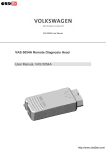
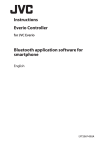
1
RAID Administrator
User’s Manual
Revision: 1.2
Date: June 2001
HighPoint Technologies, Inc.
Copyright
Copyright by HighPoint Technologies, Inc.(HighPoint), 2001. This manual
contains materials protected by International Copyright Laws. All rights
reserved. No part of this manual may be reproduced, transmitted or transcribed in any form for any purpose without the express written permission
of HighPoint.
Trademarks
Companies and products mentioned in this manual are for identification
purpose only. Product names or brand names appearing in this manual may
or may not be registered trademarks or copyrights of their respective
companies.
Notice
Every effort has been made to ensure that the information in this manual is
accurate. HighPoint assumes no liability for technical inaccuracies,
typographical, or other errors.
HighPoint provides this manual “as is “ without warranty of any kind, either
express or implied, including, but not limited to the implied warranties or
conditions of merchantability or fitness for a particular purpose. In no event
shall HighPoint be liable for any loss or profits, or for direct, indirect, special,
incidental or consequential damages arising from any defect or error in this
manual or product.
Information in this manual is subject to change without notice and does not
represent a commitment on the part of HighPoint.
i
Table of Contents
Chapter 1
Getting Started
Introduction ....................................................................... 1-1
Main Features & Benefits .................................................. 1-1
Chapter 2
Installation of Driver
Introduction ....................................................................... 2-1
Windows 98/ME ................................................................ 2-1
Windows NT4.0 ................................................................. 2-2
Windows 2000 ................................................................... 2-3
Chapter 3
Use RAID Administrator
Install RAID Administrator ................................................. 3-1
Run RAID Administrator .................................................... 3-2
Create Stripe Array ............................................................ 3-3
Create Mirror Array ............................................................ 3-4
Add/Remove Spare Disk .................................................... 3-5
Synchronize/Validate/Verify Mirror Array ............................ 3-6
Create Span Array ............................................................. 3-8
Create 0+1 Array ............................................................... 3-9
Remove Disk Array ............................................................ 3-10
Set Transfer Mode ............................................................. 3-11
Device Status .................................................................... 3-12
Hot-swapping Hard Disks of Mirror Array ........................... 3-13
Event Log .......................................................................... 3-14
ii
Chapter 4
BIOS Configuration
Enter into BIOS Configuration Utility .................................. 4-1
Create RAID ...................................................................... 4-2
Delete RAID ...................................................................... 4-3
Rebuild Mirror Array ........................................................... 4-3
Add Spare Disk ................................................................. 4-4
Remove Spare Disk ........................................................... 4-4
Set Disk Mode .................................................................. 4-4
Set Boot Disk .................................................................... 4-5
Appendix
Contact Technical Support
iii
Chapter 1
Getting Started
1.1 Introduction
1.2 Main Features & Benefits
1.1 Introduction
RAID Administrator is a Windows-based RAID management utility for HPT370
Series UDMA/ATA100 RAID Controller. By using this RAID management utility, users can easily configure and manage the hard disks connected to this
RAID Controller.
1.2 Main Features & Benefits
Below are the main features and benefits of RAID Administrator.
(1) Support RAID 0, 1,0+1 & JBOD
(2) Support Ultra ATA100(UDMA Mode 5) high performance hard disk
(3) Support up to 4 hard disks in connection
(4) Support hot-swapping hard disks of mirror array
(5) Support independent use of hard disk
(6) Support such operating systems as Windows98/ME, Windows NT4.0
& Windows 2000
(7) Support GUI software for RAID management(compatible with BIOS)
(8) Disk error alarm mechanism
(9) Support spare disk to automatically rebuild mirror array
(10) Event log for easy RAID management
(11) Plug-and-play
1-1
Chapter 2
Installation of Driver
2.1 Introduction
2.2 Windows 98/ME
2.3 Windows NT4.0
2.4 Windows 2000
2.1 Introduction
After the RAID adapter card is well installed on your computer, you shall install
its driver .
2.2 Windows 98/ME
Automatic Installation
After the computer start-up, Windows system will find the newly installed RAID
adapter and ask you to install its driver. Please follow the prompt to finish the
driver installation.
Manual Installation
If Windows can not find new hardware, the driver can be installed through the
following steps :
1. Shut down all programs.
2. Click Start-->Setup-->Control Panel, then double-click on Add
New Hardware icon.
3. Click Next in the popup window to continue.”.
4. A dialog box will appear and ask whether to let windows search
new hardware. Select No,I want to select the hardware form a
list.and then click Next to continue.
5. Hardwares of different types will be shown in the follow-on window.
Select SCSI Controllers and then click Next to continue.
6. Insert the floppy disk of driver into the floppy drive, then click Have
Disk....
7. A dialog box will pop up, input the path of driver A:\Win9X.Then
click OK to continue.
8. In the follow-on window, select HPT370 UDMA/ATA100 RAID Controller then click Next to continue.
9. Follow the system prompt to install driver. When finished, restart
the computer.
Verify Installation
When the driver has been successfully installed and the computer restarted:
1. Right-click My Computer icon on desktop, and then select Property
item from the popup menu.
2. Select Device Manager item from the popup window.
If there are two device items under SCSI Controllers, it indicates that the
driver has been installed properly.
2-1
If you cannot find these two above-mentioned device items,or there are ? or !
on device icon, it indicates that the driver has not been correctly installed and
needs reinstallation.
2.3 Windows NT4.0
Install driver under Windows NT4.0
1. Click Start-->Setup-->Control Panel, then double-click SCSI
Adapter icon.
2. In the follow-on window, select Driver item. then click Add button.
3. In the follow-on window, select Have Disk....
4. Insert the floppy disk of driver, input the path of driver A:\WinNT,
then click OK.
5. In the follow-on window, select HPT370 UDMA/ATA100 RAID Controller item, then click OK.
6. Follow the system prompt to install the driver. When finished, restart the computer.
Install driver in the process of Windows NT4.0 installation
1. Press F6 key when the system prompts Setup is inspecting
your
computer’s hardware configuration.
2. Press F6 key, the installation will continue. Later, installation pro
gram will remind user to press S key to specify other devices. Please
press S key.
3. In the follow-on Device Type window, select Other item, then
press Enter to confirm.
4. The installation program will prompt users to insert the floppy disk
of driver. Please insert it and then press Enter to confirm.
2-2
5. In the follow-on window, select HPT370 UDMA/ATA100 RAID Controller , then press Enter to confirm.
6. The follow-on interface will list the devices to be installed, in which HPT370
UDMA/ATA100 RAID Controller item should be included.( If users want
to install other devices,please operate at this time. If all devices have
been successfully installed, please go to next.)
7. Press Enter to continue the installation of Windows NT4.0.
Verify Installation
When the driver has been successfully installed and the computer restarted:
1. Click Start-->Setup-->Control Panel, and then double-click SCSI
Adapter item.
2. If there is HPT370 UDMA/ATA100 RAID Controller item in the popup
window, it indicates that the driver has been successfully installed.
Otherwise, users need to reinstall the driver.
2.4 Windows 2000
Install driver under Windows 2000
Automatic Installation
Start the computer and enter the operating system of Windows 2000, the
system will automatically detect new hardware and prompt users to install the
driver. Please insert the floppy disk of driver and follow the system prompt to
finish the driver installation and restart the computer.
2-3
Manual Installation
If Windows can not find new hardware, the driver shall be installed through the
following steps :
1. Click Start-->Setup-->Control Panel, select Add/Remove New
Hardware. In the follow-on window, Click Next to continue.
2. In the follow-on window, select the first item Add/Troubleshoot a
device, then click Next to continue.
3. In the follow-on device list, select the first item Add New Device,
then click Next to continue.
4. Then the system will ask Did you want Windows to search for
your new hardware? Please select No, I want to select the
hardware from a list.then click Next to continue.
5. In the follow-on window of device types, select SCSI and RAID
controllers, then click Next to continue.
6. In the follow-on window, select Have Disk....
7. Please insert the floppy disk of driver and input path name A:\Win2k
into Copy manufacturer’s files from: column, then click OK.
8. In the follow-on type column, select HPT370 UDMA/ATA100 RAID
Controllers.
9. Follow the system prompt to finish the installation, and restart
the computer.
Install driver in the process of Windows 2000 installation
1. If Windows 2000 is installed from the floppy drive,please let the installing program run automatically. If Windows 2000 is installed from the
CD-ROM drive, please F6 key when the message Press F6 if you
need to install third party SCSI or RAID driver appears.If it is to
type Winnt and install, after files have been copied and the computer
restarted, press F6 key when the message Setup is inspecting your
computer’s hardware configuration appears.
2. Press S key to specify additional devices when the Windows 2000
Setup window appears.
3. In the follow-on window of device type, please select Other and press
Enter to continue.
4. Insert the floppy disk of driver, then press Enter to continue.
5. The system will ask whether to install driver under WinNT or under Windows 2000, please select to install driver under Windows 2000.
6. The follow-on interface will list the devices to be installed, in which HPT370
UDMA/ATA100 RAID Controller item should be included.( If users want
to install other devices,please operate at this time. If all devices have
been successfully installed, please go to next.)
2-4
7. Press Enter to continue Windows 2000 setup.
Verify Installation
When the driver has been successfully installed and the computer restarted:
1. Right-click My Computer icon,
select Property item in the
popup menu.
2. In the popup window, select
Hardware item and then click
Device Manager button.
If there is HPT370 UDMA/ATA100 RAID Controller item in the popup
Device Manager window, it indicates that the driver has been successfully
installed. Otherwise, please reinstall the driver.
2-5
Chapter 3
Use RAID Administrator
3.1 Install RAID Administrator
3.2 Run RAID Administrator
3.3 Create Stripe Array
3.4 Create Mirror Array
3.5 Add/Remove Spare Disk
3.6 Synchronize/Validate/Verify Mirror Array
3.7 Create Span Array
3.8 Create 0+1 Array
3.9 Remove Disk Array
3.10 Set Transfer Mode
3.11 Device Status
3.12 Hot-swapping Hard Disks of Mirror Array
3.13 Event Log
3.1 Install RAID Administrator
Please take the following steps to install RAID Administrator:
1. Insert the installation CD into the CD-ROM drive.
2. Enter Windows Explorer, find and double-click the setup promgram
file
of the corresponding language version.
Setup Program of Chinese Version: Chinese\Setup\setup.exe
Setup Program of English Version: English\Setup\setup.exe
3. Click OK button, follow the program prompt to finish the installation.
4. After the installation is complete, restart the computer.
With the implicit option, the setup program will create program group: Start->Program-->RAID Administrator. This program group contains the following contents:
RAID Administrator
running program
RAID Help
help file
Uninstall RAID
uninstalling program
3-1
3.2 Run RAID Administrator
The following steps should be taken to run RAID Administrator.”:
1.Click Start-->Program-->RAID Administrator-->RAID Administrator, the below welcome interface will come up.
2.The above interface stays only for a while. Coming up is the main
interface of RAID Administrator(see below).
Menu
Disk Tree
Tool Bar
Status Pane
Tool Bar:
It provides shortcut way to execute the common commands. Commands shown
by Tool Bar can also be found under Configuration menu.
Disk Tree:
It shows the connecting information of all hard disks in two ways:View by
Device and View by Adapter.
Status Pane:
It lists the infromation and working status of selected hard disks or disk arrays.
3-2
3.3 Create Stripe Array
The following steps shall be taken to create the stripe array.
1. Click Stripe icon on the tool bar.
2. Select the strip size in the follow-on window, and then click Next
button.
3. In the follow-on dialog box, select hard disk from Available Disks
column. Add them into Stripe Array Member Disks column by clicking
the corresponding arrow button. Then click Next button.
4. In the follow-on dialog box, click Create button to create stripe array,
or click Cancel button to cancel this creation. If the cancel operation has been selected, the system will remain unchanged.
5. After the completion of creating stripe array , shut down all other
programs. Then click Yes to restart the computer, or select No to
restart the computer later .
Note:
1. At least two hard disks are needed to create the stripe array.Disks can
be connected at any cable and setted as either master or slave device.
2. The capacity of the stripe array is eaqual to the product of the number
of total hard disks and the smallest HD capacity.
Suggestion:
1. When selecting the strip size , if the user does not know which one
is suitable, please select the default size 64K.
2. In order to avoid the capacity waste , try to use hard disks with the
identical capacity to create stripe array .
3. For the consinderation of performance, if two hard disks are used,
please connect them to different IDE channels respectively.
Warning:
1. The data on all disks will be destroyed after the creation of the stripe
array.
3-3
3.4 Create Mirror Array
The following steps shall be taken to create the mirror array:
1. Click Mirror icon on the tool bar.
2. In the follow-on dialog box, select hard disks from Available Disks
column,add them into Source Disk column or Mirror Disk column
respectively by clicking the corresponding arrow button.
3. If the user wants to use a spare disk, please select Use Spare Disk
item. Then select hard disks from Available Disks column, and add
it into Use Spare Disk column.
4. Click Create to begin the creation or Cancel to exit. If you select
the cancel operation, the system will remain unchanged.
5. After the creation is complete,the program will prompt you to
synchronize mirror,slect Yes to begin or No to cancel.
6. After your selection of either , the program will prompt you to
restart your computer.
If the user has set a spare disk, when the read/write failure of either the
source disk or the mirror disk, the program will automatically use the left
normal disk and the spare disk to rebuild the mirror array, thereby providing
dual security for data.
3-4
Note:
1.At least the source disk and the mirror disk are needed in the creation of
the mirror array. The spare disk is optional.Disks can be connected at
any cable and setted as either master or slave device.
2.The capacity of either the mirror disk or the spare disk shall be no less
than that of the source disk.
3.The capacity of the mirror array is equal to that of the source disk.
Suggestion:
1.In order to avoid the capacity waste , please use hard disks with the
identical capacity to create mirror array.
Warning:
1.The creation of the mirror array will make only the data on the source
disk be preserved while the data on both the mirror disk and the spare
disk destroyed.
3.5 Add/Remove Spare Disk
If the user does not want to set a spare disk during the creation of mirror, he
can add the spare disk into the mirror array later. The user can also remove
the spare disk that has been set. The steps to add/remove the spare disk are
as follows:
1. Select the mirror array to be add/remove the spare disk.
2. Click Spare icon on the tool bar.
3. In the popup dialog box , select Add or Remove operation, then
click Next button.
4. If the user is to add the spare disk, select the hard disk to be used in
the follow-on dialog box , and then click Finish button .
5. If the user is to remove the spare disk, click Finish button in the
follow-on dialog box .
3-5
3.6 Synchronize/Validate/Verify Mirror Array
Synchronize Mirror
After the completion of creating mirror array, the data on the source disk has
not been copied to the mirror disk. The data on the source disk and the mirror
disk do not keep identical yet. The user should synchronize mirror, by which
the data on the source disk will be fully copied to the mirror disk.Thus the data
on the disks in the mirror array become identical.
Once the creation of the mirror array is finished, the user will be asked
whether to synchronize mirror at once or not. Select Yes to begin the synchronize operation or No to skip.
The status of the mirror array will remain locked if No selected to skip the
synchronize operation. The user may at any time synchronize mirror which is
in either locked status or normal status. The detailed steps to synchronize
mirror are as follows:
1. Right-click the mirror array to be synchronized.
2. Select Synchronize Mirror item from the popup menu.
The mirror array being synchronized is labeled at locked status. By selecting
this disk array, the user can see the progress of synchronizing mirror.
3-6
Validate Mirror
The user can validate the locked mirror array through the following steps:
1.Right-click the locked mirror array .
2.In the popup menu, select Validate Mirror item.
Once the mirror disk is validated, it will be implicit by the program that the data
on the mirror disk is the same with that on the source disk. And the program
will no longer ask the user to synchronize mirror. If the user wants to copy the
data from the source disk to the mirror disk, he has to synchronize mirror
manually.
Verify Mirror
The operation of the verify mirror will compare the data on the source disk and
that on the mirror disk. If any discrepancy is found between them, the program
will ask the user to synchronize mirror to keep the data in the mirror array
identical. The detailed steps to verify mirror are as follows:
1. Right-click the mirror array to be verified.
2. In the popup menu, select Verify Mirror item.
By selecting this disk array, the user can check the verification progress at the
status pane.
Suggestion:
1.
After the creation of the mirror array, if the user wants to keep the
source disk data preserved, he shall select Yes when the program asks
him whether to synchronize mirror or not.
3-7
3.7 Create Span Array
Please follow the steps below to create the span array:
1. Click Span icon on the tool bar.
2. In the popup window, select hard disks from Available Disks colume.
Add them into Span Array Member Disks colume by clicking the
corresponding arrow. Then click Next to continue.
3. In the follow-on confirmation dialog box , please click Create button
to start the creation or click Cancel button to cancel the creation . If
the user selects Cancel, the system will remain unchanged.
4. After the create operation is complete, please shut down all other
programs. And then click Yes to restart the computer. The user may
also select No to restart the computer later .
Note:
1. At least two hard disks are needed in the creation of the span array.
Disks can be connected at any cable and setted as either master or
slave device.
Warning:
1. In the creation of the span array, only the data on the first member disk
will be preserved while the data on others will be completely destroyed.
3-8
3.8 Create 0+1 Array
The following steps shall be taken to create the 0+1 array.
1. Click 0+1 icon on the tool bar.
2. Select the strip size.
3. In the popup dialog box , select the hard disks to be used, and add
them into Source Disks column or Mirror Disks column.
4. Click Create button to create or Cancel button to cancel the creation . If the user selects Cancel, the system will remain unchanged.
5. When the creation is complete, the program will ask the user to
restart the computer.
Note:
1. Four hard disks are needed in the creation of the 0+1 array.
2. In the creation of the 0+1 array, the source disk will actually be the
first stripe array composed of two hard disks, the mirror disk will
actually be the second stripe array composed of two hard disks.
3. The capacity of the stripe array as the source disk shall be not
larger than that of the stripe array as the mirror disk.
4. The capacity of the 0+1 array is equal to that of the stripe array as
the source disk.
5. Version 1.11 RAID Administrator does not support disk hotswaping
of RAID 0+1 array. User must replace the failed disk after the computer is turned off, and then rebuild the 0+1 array in BIOS.
Suggestion:
1. In order to avoid the capacity waste , please use hard disks with the
identical capacity to create the 0+1 array.
3-9
Warning:
1. The data on all member disks will be destroyed after creatng the 0+1
array.
3.9 Remove Disk Array
The following steps shall be taken to remove disk array.
1. Select the disk array to be deleted in the disk tree.
2. Click Remove icon on the tool bar.
3. In the popup dialog box, select Yes to confirm the remove operation,
select No to cancel the remove operation.
4. After the remove operation is complete, shut down all other programs.
Then click Yes to restart the computer, or select No to restart the
computer later.
Note:
1. Remove mirror array operation will generate two physical disks
with the identical data on each.
2. Remove 0+1 array operation will generate two stripe arrays with
the identical data on each.
Warning:
1. Remove stripe array operation will lead to the data on the striping
disks all destroyed.
2. Remove span array operation will lead to the data on the first disk
reserved while the data on other disks will be all destroyed.
3-10
3.10 Set Transfer Mode
The following steps shall be taken to set transfer mode of hard disk:
1.Select the hard disk in the disk tree.”.
2.Click Mode icon on the tool bar.
3.In the popup Set Transfer Mode window select the mode to be set.
4.Click OK button to finish or click Cancel button to cancel .If Cancel
button is clicked, the system will remain unchanged.
5.The setting will take effect only after the restart of computer.
Suggestion:
1. BIOS and driver of RAID Adapter can automatically detect the optimum transfer mode supported by the corresponding hard disk. Usually no need to change the transfer mode.
2. If the option box of transfer mode is gray, it means such mode is not
supported by this hard disk and can not be set.
3-11
3.11 Device Status
Raid Administrator detects the status of each device and shows their status
information with different icons to prompt users(see below).
Device is with error.
Device is normal.
Device is not operatable and needs rebooting.
Mirror Array needs to be synchronized.
Note:
1.When reading data from the mirror array, the source disk is always to
be read first, and the mirror disk will not be accessed if the data is
successfully read out from the source disk and so the mirror disk's
failure can not be detected. But when writing data to the mirror array,
both of the member disks will be accessed, so failure on either of
them can be detected.
Suggestion:
1. When a failure occurs on a member disk of the mirror array, this array
will be labeled in error status. At this time,the mirror array can continue work normally with the other normal disk. In order to avoid data
loss due to the failure of the left disk, the user shall settle the fault first
and rebuild mirror with this left normal disk.
Warning:
1. When the member disk of either the stripe array or the span array
failed ,the corresponding disk array will be labeled in error status, and
it will not be able to work.
2. If both the source disk and the mirror disk failed, the mirror array will
not be able to work. The user shall settle the fault quickly.
3-12
3.12 Hot-swapping Hard Disks of Mirror Array
During the working process of the mirror array, if there is failure of either the
source disk or the mirror disk and the spare disk has not been set, the user
can remove the failed hard disk while the computer is still on and hot-plug in a
new one. The program will automatically detect the plug-in of the new hard
disk and prompt the user whether to add the newly plugged hard disk into the
failed mirror array(see below).
Select OK to add it into the failed mirror array, the newly plugged hard disk
and the left normal member disk will generate a new mirror array that will be
automatically synchonized to keep the data on its member disks identical.
Hot-swapping hard disks of mirror array can quick recover the failed mirror
array without a shut-down of the computer or a break-off of the work, thereby
providing users with the maximum data security and the easiest operation.
Note:
1. The hard disk used to be a subsitute for the failed one must keep the
same connection to IDE and setting of jumper to that of the failed one.
For example, if the failed hard disk is connected to IDE2 and set as
master, its subsitute must be connected to IDE2 and set as master.
Warning:
1. In order to avoid any possible damage to both the system and the
device by the manual hot-swap of power and cable. Please operate hotswapping hard disks of mirror array with the special hard disk swapping box.
3-13
3.13 Event Log
Event Log window will be opened by clicking View Log icon on the tool bar.
Event log window lists all the historical operation information including event,
time & description, thereby providing reference for solving the problems in the
operation of RAID Administrator.
Event log menu provides users with functions as follows:
Set Log File:
Set the log file for recording the events .
Clear Log:
Clear all the current records in the file.
Print Log:
Print the log.
Exit:
shut the event log window.
3-14
Chapter 4
BIOS Configuration
4.1 Enter into BIOS Configuration Utility
4.2 Create RAID
4.3 Delete RAID
4.4 Rebuild Mirror Array
4.5 Add Spare Disk
4.6 Remove Spare Disk
4.7 Set Disk Mode
4.8 Set Boot Disk.
4.1 Enter into BIOS Configuration Utility
When the following information is displayed on screen during the system starting, press ctrl+H key to enter into BIOS configuration utility.
The main interface of BIOS configuration utility is as below:
Menu:
It displays all items of the operating command.
Help:
It displays the illustrating information of the current selection and the available operation prompts.
Channel Status:
It displays the status information of all devices in connection. When it is
active, users can select the device to be operated.
4-1
4.2 Create RAID
The following steps shall be taken to create RAID in BIOS.
1. Use the arrow key to select 1. Create RAID.
2. Press Enter to confirm and go to next.
3. Select 1. Array Mode in the popup subinterface and press Enter.
4. Select the intended RAID level in the popup selection box and press
Enter.
5. Select 2. Select Disk Drives in the previous subinterface and press
Enter.
6. Select the disks to be used for creating the disk array and press
Enter to confirm in the channel status zone.
7. Select 3. Start Creation Process and press Enter except that in
the selection box you have selected Stripping (RAID 0) for Performance.
8. Press Y to continue when the warning message appears.
Note:
1. If you have selected Stripping (RAID 0) for Performance in the
popup subinterface after the operation of 1. Array Mode , you should
direct go to 3. Strip Size 64K and then select 4. Start Creation
Process . The default strip size is 64K .
2. Different warning messages appear according to different RAID levels.
4-2
4.3 Delete RAID
The following steps shall be taken to delete RAID.
1. In the menu zone, select 2. Delete RAID , press Enter to confirm
this operation and go to next.
2. In the validated channel status zone, use the arrow key to select
the disk array to be deleted and press Enter to confirm.
3. Press Y when warned Are you sure you want to remove the disk
array?
4.4 Rebuild Mirror Array
The following steps shall be taken to rebuild the mirror array.
1. In the menu zone, select 3. Rebuild Mirror Array , press Enter to
confirm this operation and go to next.
2. In the menu zone of the popup subinterface, select 1. Select
Source Disk: None and press Enter to confirm.
3. In the validated channel status zone, select the source disk of the
mirror array and then press Enter.
4. In the menu zone of the popup subinterface, select 2. Select Target
Disk: None and press Enter to confirm.
5. In the validated channel status zone, select the target disk of the
mirror array and then press Enter.
6. In the menu zone of the popup subinterface, select 3. Start Duplication Process and press Enter to confirm.
7. Press Y when asked The last time rebuild not completed.
Continue?
4-3
4.5 Add Spare Disk
The following steps shall be taken to add the spare disk.
1. In the menu zone, select 4. Add Spare Disk and press Enter to
confirm.
2. In menu zone of the popup subinterface, select 1. Select Mirror
Array: None and press Enter to confirm.
3. In the validated channel status zone, select the mirror array and
press Enter to confirm.
4. In the menu zone of the popup subinterface , select 2. Select Spare
Drive: None and press Enter to confirm.
5. In the validated channel status zone, select the spare disk to be
added and press Enter to confirm.
4.6 Remove Spare Disk
The following steps shall be taken to remove the spare disk.
1. In the menu zone, select 5. Remove Spare Disk and press Enter to
confirm.
2. The 1. Select Mirror Array: None item appears in the menu zone of
the popup subinterface.
3. In the validated channel status zone, select the spare disk to be
removed and press Enter to confirm.
4.7 Set Disk Mode
The followng steps shall be taken to set the disk mode.
1. Select 6. Set Disk Mode in the menu zone and press Enter to
confirm.
2. Select the disk mode to be set in the popup selection box and press
Enter to confirm.
4-4
4.8 Set Boot Disk.
The following steps shall be taken to set the boot disk:
1. In the menu zone, select 7. Set Boot Disk item, press Enter to
confirm this operation and go to next .
2. In the validated channel status zone , use the arrow key to select the
boot device and press Enter to confirm.
Note:
1. The Set Boot Disk item appears on condition that no hard disk is connected to IDE on motherboard.
2.
After the boot disk is set, its status will become Boot.
4-5
Appendix
Contact Technical Support
Contact Technical Support
HighPoint provides users with quick and satisfied support service. If there is
any question when using when using our products, you may get help though
the following ways: ·
First, please read this manual carefully;
Second, please visit our website: www.highpoint-tech.com for the
latest product information;
If you cannot solve the problem through the above ways, please feel free to
contact our Technical Support Departmentl: [email protected]
Thank you for choosing HighPoint products!
i