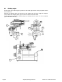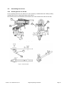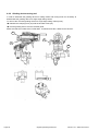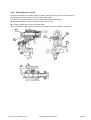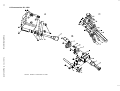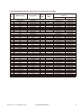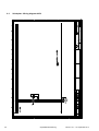
1
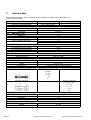
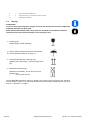
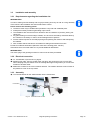
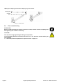
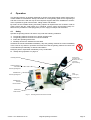
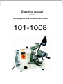
Operating manual Version 1.0.4 Grinding machine for burins and tools 101-1008 Table of contents 1 Safety 1.1 1.2 1.2.1 1.2.2 1.3 1.4 1.5 1.5.1 1.5.2 1.6 1.7 1.8 1.9 1.9.1 1.9.2 1.10 1.11 1.12 1.13 2 Technical data 2.1 2.2 2.3 2.4 2.5 2.6 2.7 2.8 2.9 2.10 2.11 3 Scope of delivery ....................................................................................................................................17 Storage ...................................................................................................................................................18 Installation and assembly .......................................................................................................................19 Requirements regarding the installation site...........................................................................................19 Electrical connection...............................................................................................................................19 Assembly ................................................................................................................................................19 First commissioning ................................................................................................................................20 Operation 4.1 4.2 4.3 4.4 4.5 4.6 4.6.1 4.6.2 4.6.3 Page 2 Electrical connection...............................................................................................................................14 Speed .....................................................................................................................................................14 Adjustable angle .....................................................................................................................................14 Travels ....................................................................................................................................................14 Grinding wheels ......................................................................................................................................14 Grinding devices .....................................................................................................................................14 Collet seat...............................................................................................................................................14 Dimensions .............................................................................................................................................14 Environmental conditions........................................................................................................................14 Emissions ...............................................................................................................................................15 Dimensions cup wheel............................................................................................................................16 Assembly 3.1 3.2 3.3 3.3.1 3.3.2 3.3.3 3.4 4 Representation Conventions ....................................................................................................................5 Safety instructions (warning notes)...........................................................................................................6 Classification of hazards...........................................................................................................................6 Other pictograms ......................................................................................................................................7 Intended use .............................................................................................................................................7 Possible dangers caused by the grinding machine for burins ..................................................................8 Qualification of personnel .........................................................................................................................8 Target group .............................................................................................................................................8 Authorized personnel................................................................................................................................9 Operators positions...................................................................................................................................9 Safety measures during operation..........................................................................................................10 Safety devices ........................................................................................................................................10 Safety check ...........................................................................................................................................10 ON / Off - Switch.....................................................................................................................................12 Spark protection......................................................................................................................................12 Personal protective equipment for special works ...................................................................................12 Safety during operation...........................................................................................................................12 Accident report........................................................................................................................................13 Electrical system.....................................................................................................................................13 Safety......................................................................................................................................................21 Assembly and function............................................................................................................................23 Handling the tool holder..........................................................................................................................24 Setting the shaft shoulder .......................................................................................................................25 Grinding angles.......................................................................................................................................26 Assembling the devices ..........................................................................................................................27 Grinding device for drill bit ......................................................................................................................27 Grinding device turning tool ....................................................................................................................28 Grinding device end mill .........................................................................................................................29 Original operating instructions Version 1.0.4 dated 2014-09-19 5 Maintenance 5.1 5.1.1 5.1.2 5.2 5.2.1 5.3 6 Ersatzteile - Spare parts 6.1 6.1.1 6.2 6.2.1 6.3 6.4 7 Safety ..................................................................................................................................................... 30 Preparation............................................................................................................................................. 30 Restarting ............................................................................................................................................... 30 Inspection and maintenance .................................................................................................................. 31 Exchange of the abrasive wheel ............................................................................................................ 31 Repair ..................................................................................................................................................... 31 Ersatzteilzeichnung - Drawing spare parts ............................................................................................33 Ersatzteilliste - Spare part list ............................... ................................................................................. 34 Accessories ........................................................................................................................................... 36 Spare part list accessories .................................................................................................................... 37 Schaltplan - Wiring diagram 400V.......................................................................................................... 38 Schaltplan - Wiring diagram 230V.......................................................................................................... 39 Annex 7.1 7.2 7.3 7.4 7.5 7.6 7.6.1 7.6.2 7.6.3 7.6.4 7.7 Copyright ................................................................................................................................................ 40 Terminology/Glossary ............................................................................................................................ 40 Change information manual ................................................................................................................... 40 Product follow-up.................................................................................................................................... 40 Liability claims for defects / warranty...................................................................................................... 41 Advice for disposal / Options of re-use................................................................................................... 41 Decommissioning ................................................................................................................................... 42 Disposal of the packaging of the new machine ...................................................................................... 42 Disposal of the used machine ................................................................................................................ 42 Disposal of electrical and electronic components .................................................................................. 42 Disposal via municipal collecting points ................................................................................................. 43 Version 1.0.4 dated 2014-09-19 Original operating instructions Page 3 Preface Dear customer, Thank you very much for purchasing a product made by BEIPING Machine. BEIPING metal working machines offer a maximum of quality, technically optimum solutions and convince by an outstanding price performance ratio. Continuous enhancements and product innovations guarantee state-of-the-art products and safety at any time. Before commissioning the machine please thoroughly read these operating instructions and get familiar with the machine. Please also make sure that all persons operating the machine have read and understood the operating instructions beforehand. Keep these operating instructions in a safe place nearby the machine. Information The operating instructions include indications for safety-relevant and proper installation, operation and maintenance of the machine. The continuous observance of all notes included in this manual guarantee the safety of persons and of the machine. The manual determines the intended use of the machine and includes all necessary information for its economic operation as well as its long service life. In the paragraph "Maintenance" all maintenance works and functional tests are described which the operator must perform in regular intervals. The illustration and information included in the present manual can possibly deviate from the current state of construction of your machine. Being the manufacturer we are continuously seeking for improvements and renewal of the products. Therefore, changes might be performed without prior notice. The illustrations of the machine may be different from the illustrations in these instructions with regard to a few details. However, this does not have any influence on the operability of the machine. Therefore, no claims may be derived from the indications and descriptions. Changes and errors are reserved! Your suggestion with regard to these operating instructions are an important contribution to optimising our work which we offer to our customers. For any questions or suggestions for improvement, please do not hesitate to contact our service department. If you have any further questions after reading these operating instructions and you are not able to solve your problem with a help of these operating instructions, please contact your specialised dealer or directly the company BEIPING. Page 4 Original operating instructions Version 1.0.4 dated 2014-09-19 1 Safety 1.1 Representation Conventions gives additional advices calls on you to act enumerations This part of the operating instructions explains the meaning and use of the warning notices included in these operating instructions, defines the intended use of the grinding machine for burins, points out the dangers that might arise for you or others if these instructions are not observed, informs you about how to avoid dangers. In addition to these operation instructions, please observe the applicable laws and regulations, the legal regulations for accident prevention. When installing, operating, maintaining and repairing the grinding machine for burins it is necessary to observe the European standards The still applicable country-specific regulations need to be applied for the not yet for the corresponding national country law implemented German standards. If required it is necessary to take the corresponding measures to comply with the country-specific regulations before commissioning the grinding machine for burins. Please keep this documentation always close to the grinding machine for burins. Version 1.0.4 dated 2014-09-19 Original operating instructions Page 5 1.2 Safety instructions (warning notes) 1.2.1 Classification of hazards We classify the safety instructions into different levels. The table below gives an overview of the classification of symbols (pictograms) and signal words for the specific danger and its (possible) consequences. Pictogram Signal word Definition/Consequences DANGER! Imminent danger that will cause severe injury of death to the staff. WARNING! A danger that might cause severe injury to the staff or can lead to death. CAUTION! Danger of unsafe procedure that might cause injury to the staff or property damages. Situation that could cause damage to the machine and products and other types of damage. ATTENTION! No risk of injury to the staff. Application tips and other important or useful information and notes. No dangerous or harmful consequences for the staff or objects. INFORMATION In case of specific dangers, we replace the pictogram by or general danger Page 6 by a warning of injury of hands, hazardous electrical voltage, Original operating instructions rotating parts. Version 1.0.4 dated 2014-09-19 1.2.2 Other pictograms Warning of flammable substances! Disconnect the mains plug! Activation forbidden! Use protective glasses! Use protective boots! Contact address Protect the environment! 1.3 Intended use Use The grinding machine for burins is designed and manufactured to be used in a non-explosive environment. The grinding machine for burins must only be used to manufacture single edge milling cutters, stamps and to regrind tools, cutting tools such as end milling cutters, drills, TIG welding electrodes, etc. If the grinding machine for burins is used in any way other than described above, modified with- The machine out the approval of the company BEIPING Maschinen Germany GmbH or used in any other is no longer used as preway then the grinding machine for burins is being used improperly. We do not take any liability for damages caused by improper use. scribed! We expressly point out that the guarantee or CE conformity will expire due to any constructive technical or procedural changes which had not been performed by the company BEIPING Maschinen Germany GmbH. It is also part of intended use that you observe the operating values and setting of the data grinding machine for burins, observe the operating instructions, observe the inspection and maintenance instructions. "Technical data“ on page 14 Version 1.0.4 dated 2014-09-19 Original operating instructions Page 7 1.4 Possible dangers caused by the grinding machine for burins The grinding machine for burins is state-of-the-art. Nevertheless, there is a residual risk as the grinding machine for burins operates with at high speeds, rotating parts, with an abrasive wheel (flying sparks) with electrical voltages and currents. We have used construction resources and safety techniques to minimize the health risk for the staff resulting from these hazards. If the grinding machine for burins is used and maintained by the staff who are not duly qualified, there may be a risk resulting from incorrect or unsuitable maintenance of the grinding machine for burins. INFORMATION All staff involved in assembly, commissioning, operation and maintenance, must be duly qualified, strictly follow these operating instructions. In the event of intended use there may be a risk to the persons, there may be a risk to the grinding machine for burins and other material values, the correct function of the grinding machine for burins may be affected. Always disconnect the mains plug from the socket before performing any cleaning or maintenance works. 1.5 Qualification of personnel 1.5.1 Target group This manual is addressed to the operating companies, the operators, the staff for maintenance works. Therefore, the warning notes refer to both, operation and maintenance staff of the grinding machine for burins. Determine clearly and explicitly who will be responsible for the different activities on the machine (operation, maintenance and repair). Unclear responsibilities constitute a safety risk! The qualifications of the staff for the different tasks are mentioned below: Operator The operator is instructed by the operating company about the assigned tasks and possible risks in case of improper behaviour. Any tasks which need to be performed beyond the operation in the standard mode must only be performed by the operator if it is indicated in these instructions and if the operating company expressively commissioned the operator. Electrical specialist Due to his professional training, knowledge and experience as well as his knowledge of respective standards and regulations the electrical specialist is able to perform works on the electrical system and to recognise and avoid any possible dangers himself. Page 8 Original operating instructions Version 1.0.4 dated 2014-09-19 The electrical specialist is specially trained for the working environment in which he is working and knows the relevant standards and regulations. Specialist staff Due to its professional training, knowledge and experience as well as his knowledge of relevant regulations the specialist staff is able to perform the assigned tasks and to recognise and avoid any possible dangers himself. Instructed persons Instructed persons were instructed by the operating company about the assigned tasks and any possible risks in case of improper behaviour. 1.5.2 Authorized personnel WARNING! Incorrect use and maintenance of the grinding machine for burins constitutes a danger for the staff, objects and the environment. Only authorized staff may operate the grinding machine for burins and tools! Persons authorized to operate and maintain should be trained technical personnel and instructed by the ones who are working for the operating company and for the manufacturer. The operating company must train the personnel, instruct the personnel in regular intervals (at least once a year) on - all safety standards that apply to the machine, - the operation, - accredited technical guidelines, check personnel‘s state of knowledge, document the trainings/instructions, require personnel to confirm participation in training/instructions by means of a signature, check whether the personnel is working safety- and risk-conscious and observe the operating instructions. Obligations of the of the operating company, The operator must have followed a training on the operation of the grinding machine for burins, know the function and performance, before taking the machine in operation Obligations of the operator - have read and understood the operating instructions, - be familiar with all safety devices and instructions. For work on the following parts there are additional requirements: Electrical parts or operating agents: shall only be performed by an electrician or under the guidance and supervision of an electrician. Additional requirements regarding the qualification Before starting work on electrical parts or operating agents, following measures are to be performed in the following order. Disconnect all poles. Secure against switching on. Check if the machine is zero potential. 1.6 Operators positions The operator’s position is in front of the grinding machine for burins. Version 1.0.4 dated 2014-09-19 Original operating instructions Page 9 INFORMATION The mains plug of the grinding machine for burins must be freely accessible. 1.7 Safety measures during operation CAUTION! Risk by inhaling health hazardous dusts and fogs. Depending on the materials which need to be treated and the agents which are used, dusts and fogs may be generated which endanger your health. Make sure that the generated health hazardous dusts and fogs are safely sucked-off at the place of origin and that they are dissipated or filtered. To do so, use a suitable extraction unit. CAUTION! Risk of fire and explosion by using inflammable materials or cooling-lubricating agents. Before processing inflammable materials (e.g. aluminium, magnesium) or using inflammable auxiliary materials (e.g. spirit) it is necessary to take additional preventive measures in order to safely avoid health risks. 1.8 Safety devices Use the grinding machine for burins only with properly functioning safety devices. Stop the grinding machine for burins immediately if there is a failure on the safety device or if it is not functioning for any reason. It is your responsibility! If a safety device has been activated the grinding machine for burins must only be used if you have removed the cause of the failure, have verified that there is no danger resulting for the staff or objects. WARNING! If you bypass, remove or deactivate a safety device in any other way, you are endangering yourself and other staff working with the grinding machine for burins and tools. The possible consequences are: extremely serious injuries by bursting of the abrasive wheel, injury of eyes due to flying sparks, injury of hands, a fatal electrocution. WARNING! The separating protective covers which are made available and delivered together with the machine are designed to reduce the risk of workpieces or fragments of tools or workpieces flying off at high speed - however, this cannot be completely avoided. Always work carefully and observe the limit values of your grinding process. 1.9 Safety check Check the grinding machine for burins before each start-up or at least once per shift. Inform the person responsible immediately of any damage, defect or change in operating function. Check all safety devices at the beginning of each shift (at continuous operation), once a week (with the machine in operation), after every maintenance and repair work. Page 10 Original operating instructions Version 1.0.4 dated 2014-09-19 Check that prohibition, warning and information signs and the labels on the grinding machine for burins are legible (clean them, if necessary), are complete (replace if necessary). INFORMATION Use the following table for organizing the checks. General check Equipment Check Protective covers Mounted, firmly bolted and not damaged Signs, Markings Installed and legible Date: OK Checked by (signature): Functional test Equipment Check Emergency stop After pressing the EMERGENCY STOP impact switch or the pressure switch OFF the grinding machine for burins stop. push button ON-OFF switch Date: Version 1.0.4 dated 2014-09-19 OK The grinding machine for burins must only be restarted after having disconnected and reconnected the mains plug if the ONswitch was pressed again. Checked by (signature): Original operating instructions Page 11 1.9.1 ON / Off - Switch The switch is provided with an emergency stop function. Open the cap of the switch in order to switch on the grinding machine for burins. Cap ON / Off - Switch Img.1-1: ON / Off - Switch CAUTION! After actuating the EMERGENCY-STOP button or the ON / OFF switch, the grinding machine for burins coasts for about 30 seconds. 1.9.2 Spark protection The protective cover of the abrasive wheel reduces the number of flying sparks getting into your eyes during machining. Use protective glasses! 1.10 Personal protective equipment for special works Protect your face and eyes: wear a safety helmet with facial protection when performing works where your face and eyes are exposed to hazards. Wear safety shoes when carrying the grinding machine for burins. 1.11 Safety during operation We specially point out the specific dangers when working with and on the grinding machine for burins and tools. WARNING! Before switching on the grinding machine for burins, make sure that there are no dangers generated for persons, no objects are damaged. WARNING! Fire and explosion due to sparks. Do not operate the grinding machine for burins and tools nearby combustible or explosive material. Avoid any risky working practices: Make sure that nobody is endangered by your work. Wear safety goggles. The instructions mentioned in these operating instructions have to be strictly observed dur- ing assembly, operation, maintenance and repair. Do not work on the grinding machine for burins, if your concentration is reduced, for exam- ple, because you are taking medication. Observe the accident prevention regulations issued by your Employers Liability Insurance Association or other competent supervisory authority, responsible for your company. Page 12 Original operating instructions Version 1.0.4 dated 2014-09-19 Inform the supervisor about all endangerments or errors. 1.12 Accident report Inform your superiors and BEIPING Maschinen Germany GmbH immediately in the event of accidents, possible sources of danger and any actions which almost led to an accident (near misses). There are many possible causes for "near misses". The sooner they are notified, the faster the causes can be eliminated. INFORMATION We highlight specific dangers when performing works on the grinding machine for burins and tools in the description of that work. 1.13 Electrical system "Schaltplan - Wiring diagram 400V“ on page 38 "Schaltplan - Wiring diagram 230V“ on page 39 Have the machine and/or the electrical equipment checked regularly, at least every six months. Immediately eliminate all defects such as loose connections, defective wires, etc. A second person must be present during work on live components to disconnect the power in the event of an emergency. Immediately disconnect the grinding machine for burins and tools if there are any anomalies in the power supply! Version 1.0.4 dated 2014-09-19 Original operating instructions Page 13 2 Technical data The following information are the dimensions and indications of weight and the manufacturer‘s approved machine data. 2.1 2.2 2.3 2.4 2.5 Electrical connection Motor power machine type 400V Motor power machine type 230V Speed 101-1008(230V) 101-1008(400V) 230 V / 50Hz / 250 W 3x400 V / 50Hz / 370 W - Speed grinding disc, diamond disc Max. grinding speed Speed motor 5000 min-1 35 m/s 2750 min-1 Vertical / rear Horizontal /taper grinding Negative Setting positions rotation angle 0- 40° 0-180° 0- 52° 15° 180° Adjustable angle Travels Travel tool holder Fine adjustment range tool holder Fine adjustment range length axis Division scale infeed 140mm 18mm 6mm 0.01mm Corundum cup wheel Diamond cup wheel Ø100 x 50 x Ø20 Ø100 x 50 x Ø20 Single edge milling cutter Turning tool Drill bit End mill cutter Up to Ø 12mm (Standard scope of delivery) Up to 21mm x 21mm Up to Ø 12mm Up to Ø 12mm (Standard scope of delivery) Grinding wheels 2.6 Grinding devices 2.7 Collet seat 355E , DIN 6341 355E , DIN 6341 G = S20x2 d = 20 D = 28 L = 137 35° - 385E (5C) , DIN 6341 385E (5C) , DIN 6341 G = 26.45 x 1/24" d = 31.75 D = 37.5 L = 89 - 20° 2.8 Dimensions 2.9 Environmental conditions Page 14 Height [mm] Depth [mm] Width [mm] Net weight [ kg ] 340 450 350 50 Temperature Humidity 5-35 °C 25 - 80% Original operating instructions Version 1.0.4 dated 2014-09-19 2.10 Emissions The generation of noise (emission) emitted by the grinding machine for burins is 72 dB(A). If the grinding machine for burins is installed in an area where various machines are in operation, the noise exposure (immission) on the operator of the grinding machine for burins at the working place may exceed 80 dB(A). INFORMATION This numerical value was measured on a new machine under proper operating conditions. Depending on the age respectively on the wear of the machine it is possible that the noise behaviour of the machine changes. Furthermore, the factor of the noise emission is also depending on manufacturing influencing factors, e.g. speed, material and clamping conditions. INFORMATION The mentioned numerical value is the emission level and not necessarily a safe working level. Though there is a dependency between the degree of the noise emission and the degree of the noise disturbance it is not possible to use it reliably to determine if further precaution measures are required or not. The following factors influence the actual degree of the noise exposure of the operator: Characteristics of the working area, e.g. size or damping behaviour, Other noise sources, e.g. the number of machines, Other processes taking place in the proximity and the period of time during which the operator is exposed to the noise. Furthermore, it is possible that the admissible exposure level might be different from country to country due to national regulations. This information about the noise emission shall allow the operator of the machine to more easily evaluate the endangering and risks. CAUTION! Depending on the overall noise exposure and the basic limit values the machine operators has to wear an appropriate hearing protection. We generally recommend to use a noise protection and a hearing protection. Version 1.0.4 dated 2014-09-19 Original operating instructions Page 15 2.11 Page 16 Dimensions cup wheel Original operating instructions Version 1.0.4 dated 2014-09-19 3 Assembly 3.1 Scope of delivery When the machine is delivered, check immediately that the machine has not been damaged during transport and that all components are included. To do so take all parts out of the packaging and compare the parts with the figure below to be able to assign the individualparts. INFORMATION The machine 101-1008(400V) is supplied without machine illumination. The machine 101-1008(230V) is supplied with machine illumination. 6 11 9 7 8 12 10 5 4 3 1 Img.3-1: Figure No 2 Accessories Quantity Description 1 5 Collets type 355E D=28 , L = 123 ; 35° DIN 6341 Size 4mm ; 6mm ; 8mm ; 10mm ; 12mm or Collets type 385E D=28 , L = 89 ; 20° DIN 6341 Size 4mm ; 6mm ; 8mm ; 10mm ; 12mm 2 1 Corundum cup wheel Ø100 x 50 x Ø20 Diamond cup wheel Ø100 x 50 x Ø20 (mounted on the machine when delivered) 3 1 Spare round belt 4 1 Socket to mount the cup wheels 5 1 Device to regrind turning tools 6 1 Device to regrind end mills 7 1 Device to regrind twist drills 8 1 Clamping ring for the device twist drill 9 1 Clamping piece for the device twist drill Version 1.0.4 dated 2014-09-19 Original operating instructions Page 17 10 1 Crank to clamp the tool collet chuck 11 2 Hook wrench size 38 - 42 to reclamp the collet chuck seat 12 1 Handwheel shaft shoulder 3.2 Storage ATTENTION! In case of wrong and improper storage electrical and mechanical machine components might get damaged and destroyed. Store packed and unpacked parts only under the intended environmental conditions. Follow the instructions and information on the transport case. Fragile goods (Goods require careful handling) Protect against moisture and humid environment "Environmental conditions“ on page 14 Prescribed position of the packing case (Marking of the top surface - arrows pointing to the top) Maximum stacking height Example:not stackable - do not stack a second packing case on top of the first one. Consult BEIPING Maschinen Germany GmbH if the machine and accessories are stored for more than three months or are stored under different environmental conditions than those given here. "Information“ on page 5 Page 18 Original operating instructions Version 1.0.4 dated 2014-09-19 3.3 Installation and assembly 3.3.1 Requirements regarding the installation site INFORMATION In order to attain good functionality and a high processing accuracy as well as a long durability of the machine the installation site should fulfil certain criteria. Please observe the following points: The device must only be installed and operated in a dry and well-ventilated place. Avoid places nearby machines generating chips or dust. The installation site must be free from vibrations also at a distance of presses, planing ma- chines, etc. Any parts sticking out such as stops, handles, etc. have to be secured by measures taken by the customer if necessary in order to avoid endangerment of persons. Provide sufficient space for the staff preparing and operating the machine and transporting the material. Also consider that the machine is accessible for setting and maintenance works. Provide for sufficient illumination (Minimum value at the working place: 300 lux). If the illuminance is too little make sure to provide additional illumination. INFORMATION The mains plug of the grinding machine for burins must be freely accessible. 3.3.2 Electrical connection "Qualification of personnel“ on page 8 Machine type 400V: Connect a CEE-400V-16A plug. We recommend you to use a CEE400V-16A plug with pole switch since the rotating field might change when you connect the machine to another outlet. Make sure to switch to the correct rotation direction. The rotation direction arrow is found on the protective cover of the cup wheel. 3.3.3 Assembly Turn the handwheel for the shaft shoulder into the seat thread. Hand wheel 12 Img.3-2: Handwheel shaft shoulder Version 1.0.4 dated 2014-09-19 Original operating instructions Page 19 Plug the clamping piece and the clamping ring on the device. Clamping ring Clamping piece 12 Img.3-3: Device drill bit 3.4 First commissioning ATTENTION! Before commissioning the machine check all screws, fixtures and the clamping lever and tighten up the screws if necessary! CAUTION! The cup wheel might get damaged during transportation. Let the grinding machine for burins and tools run in for about 15 minutes before you start grinding. "Personal protective equipment for special works“ on page 12. Page 20 Original operating instructions Version 1.0.4 dated 2014-09-19 4 Operation This grinding machine is generally designed to grind a single edge milling cutters (burins) but it is also suitable to manufacture stamps, electrodes or round grinding parts and for regrinding of end mills on the face. With the help of the workpiece supports which are available as accessories it is possible to grind round tool bits, milling cutters and drill bits. By means of the versatile slewing and setting options all requirements are covered in order to grind a graver with any cutter shape (e.g. cylindrical, conical, centric and eccentric radii). Furthermore it is possible to create polygones (3- to 24- edge) on stamps and electrodes. 4.1 Safety Operate the grinding machine for burins only under the following conditions: The grinding machine for burins is in proper working order. The grinding machine for burins is used as intended. Follow the operating instructions. All safety devices are installed and activated. All failures should be eliminated immediately. Stop the grinding machine for burins immediately in the event of any failure in operation and make sure that the grinding machine for burins can not be started up accidentally or without authorization. Notify the person responsible immediately of any modification. "Safety during operation“ on page 12 Dressing diamond Diamond disc (Corundum disc included in the scope of delivery) Bayonet locking Clamping screw of the shaft to shift the grinding disc Handwheel to shift the grinding disc Scale (Point angle) Clamping lever Handwheel to shift the the tool holder Hand wheel shaft soulder Img.4-1: Grinding machine for burins and tools Version 1.0.4 dated 2014-09-19 Original operating instructions Page 21 Bayonet locking Scale turning angle Crank to clamp the collet chuck Shaft tool carrier Scale relief angle Page 22 Original operating instructions Version 1.0.4 dated 2014-09-19 4.2 Assembly and function The driving pulley (14) seated on the motor is driven by a round belt (3) the pulley (19) and the spindle. Switch (Emergency-Stop switch) (15) to switch the machine on and off. Handwheel (17) for axial adjustment of the shaft for the tool holder (16). Handwheel (12) to set the stop of the shaft by means of the tool holder (16). Use the clamping lever (18) in order to clamp the shaft of the tool carrier (16). Handwheel (12) for fine setting of the cup wheel (2) by means of the clamping screw (21). Dressing diamond (24) to dress the cup wheel (2). 19 3 14 12 21 9 24 18 2 15 17 16 Img.4-2: Grinding machine for burins and tools Version 1.0.4 dated 2014-09-19 Original operating instructions Page 23 4.3 Handling the tool holder The tool which needs to be machined is clamped in the collet chucks (30). The collet chucks are tightened by means of the crank (31). The fine adjustment of the bushing (32) which is located in the collet chuck (30) is performed in axial direction using the knurled screw (33) on the carriage. The division of the scale disc (34) is performed in steps of 15°. The bolt (35) which fixes the scale disc (34) is held by means of the bayonet locking (36). The scale disc (34) can be freely moved when the bayonet locking (36) is cammed in. It is possible to adjust the upper part of the support by means of the screw (37). Read the values from the scale (38) and from the vernier (39) for exact setting. If both values of the scale (38) with (39) are set to 0 the grinding machine for burins is in the basic setting. In order to turn the slewing arm (40) at an angle of up to 90° it is necessary to release the clamping lever (41). It is possible to tilt the slewing arm (40) at an angle of up to 40° by means of an clamping lever (42). It is necessary to tighten the lever (43) in order to fix the tool holder on the shaft. The clamping lever (44) fixes the shaft. 32 36 35 34 31 30 38 40 33 44 37 39 41 42 43 Img.4-3: Tool holder Page 24 Original operating instructions Version 1.0.4 dated 2014-09-19 4.4 Setting the shaft shoulder Clamp the tool in the collet chuck (30) and release the lever (18) in order to be able to move the shaft (16). The stop of the shaft (16) is set for the tool carrier by means of the handwheel (12). If the handwheel (12) is turned in the possible rotation movement of the shaft to the stop is being reduced. Clamp the clamping lever (44) in order to control the rotation movement. 31 30 44 18 12 16 12 Version 1.0.4 dated 2014-09-19 Original operating instructions Page 25 4.5 Grinding angles Set the upper part of the support by means of the scale (38) and the vernier (39). Both values must be set to 0. Release the clamping lever (42) and then tilt the slewing arm (40) at an angle of 0 degree. Then, release the clamping lever (18) in order to be able to move the shaft. Set the slewing arm (40) to the desired angle by releasing the lever (44). Turn the handwheel (12) in order to set the stop. 38 40 44 37 39 42 18 12 Page 26 Original operating instructions Version 1.0.4 dated 2014-09-19 4.6 Assembling the devices 4.6.1 Grinding device for drill bit On the grinding device for the drill bit it is not necessary to disassemble the already existing grinding device for the single edge milling cutter (burin). Pull the stop (48) out of the bushing and introduce (49). (50) is fixed in the collect chuck (30). 30 46 45 48 44 Img.4-4: Device single edge milling cutter 49 50 Img.4-5: Device twist drill Version 1.0.4 dated 2014-09-19 Original operating instructions Page 27 4.6.2 Grinding device turning tool In order to assemble the grinding device for milling cutters and turning tools it is necessary to disassemble the grinding device for single edge milling cutters. To remove the mounted grinding device for single edge milling cutters (burin): Release the clamping lever (45) and the knurled screw (46). Pull the grinding device over the dovetail guide. Make sure that the V-ledge does not fall down. If required reset the V-ledge for the devices. 30 46 45 48 44 Img.4-6: Device single edge milling cutter Img.4-7: Device HSS turning tool Page 28 Original operating instructions Version 1.0.4 dated 2014-09-19 4.6.3 Grinding device end mill In order to assemble the grinding device for milling cutters and turning tools it is necessary to disassemble the grinding device for single edge milling cutters. To remove the mounted grinding device for single edge milling cutters (burin): Release the clamping lever (45) and the knurled screw (46). Pull the grinding device over the dovetail guide. Make sure that the V-ledge does not fall down. If required reset the V-ledge for the devices. 30 46 45 48 44 Img.4-8: Device single edge milling cutter Img.4-9: Device end mill Version 1.0.4 dated 2014-09-19 Original operating instructions Page 29 5 Maintenance In this chapter you will find important information about Inspection Maintenance Repair of the grinding machine for burins and tools. ATTENTION ! Properly performed regular maintenance is an essential prerequisite for operational safety, failure-free operation, long service life of the grinding machine for burins and the quality of the products to be manufactured. Installations and equipment from other manufacturers must also be in good order and condition. 5.1 Safety WARNING! The consequences of incorrect maintenance and repair work may include: Heaviest injuries of the persons working on the grinding machine for burins and tools Damages to the grinding machine for burins Only qualified staff should carry out maintenance and repair work on the grinding machine for burins and tools. 5.1.1 Preparation WARNING! Only carry out work on the grinding machine for burins and tools if it has been switched off using the mains plug. 5.1.2 Restarting WARNING! Before starting the grinding machine for burins, make sure that there exists no dangers generated for persons, no damage to the grinding machine for burins and tools. Page 30 Original operating instructions Version 1.0.4 dated 2014-09-19 5.2 Inspection and maintenance The type and extent of wear depends to a large extent on individual usage and service conditions. Regularly clean the grinding machine for burins from grinding dust. Soiling by grinding dust in the slideways leads to relevant wear. If necessary - use compressed air to clean the grinding machine for burins from grinding dust. If you recognize much positive allowance of the slideways, fasten the adjustment screws accordingly. Lubricate the lubricating nipples in regular intervals. 5.2.1 Exchange of the abrasive wheel WARNING! Check if the cup wheels are damaged or have cracks before mounting them. If a new cup wheel is damaged or shows cracks it must not be mounted in any way. 5.3 Repair Request for a service technician of the company BEIPING Maschinen Germany GmbH for all repairs or send us the grinding machine for burins and tools. If the repairs are carried out by qualified technical staff, they must follow the indications given in these operating instructions. The company BEIPING Maschinen Germany GmbH does not take any liability nor does it guarantee against damage and operating malfunctions resulting from failure to observe this operating instructions. For repairs only use faultless and suitable tools only original parts or parts from series expressly authorised by BEIPING Maschinen Ger- many GmbH. Version 1.0.4 dated 2014-09-19 Original operating instructions Page 31 Page 32 Original operating instructions Version 1.0.4 dated 2014-09-19 Version 1.0.4 19. September 2014 6 Ersatzteile - Spare parts 6.1Ersatzteilzeichnung - Drawing spare parts 101-1008 Originalbetriebsanleitung Abb.6-1: Ersatzteilzeichnung - Drawing spare parts 101-1008 33 34 Pos. 6.1.1Ersatzteilliste - Spare part list 101-1008 Bezeichnung Designation 1 2 3 4 5 6 7 8 9 10 11 12 13 14 15 16 17 18 19 20 21 22 23 24 25 26 27 28 29 30 31 32 33 34 35 36 37 38 39 40 41 42 43 44 45 46 47 48 49 50 51 52 53 54 55 56 57 58 59 60 61 62 Handrad mit Skala Schraube Skalenring Halter Schraube Feder Sechskantmutter Welle Maschinenfuß Abdeckung Handrad Gewindestift Schmiernippel Unterbau Riemen Motor Handrad mit Skala Schraube Schraube Schraube Schraube Skalenring Ring Schraube Gewindestift Schraube Handhebel Antrieb 12 V LED Lampe Motorflansch Schraube Riemenscheibe Scheieb Schraube Abdeckung Axiallager Stift Halter Klemmschraube Klemmvorrichtung Ein-Aus-Schalter Abdeckung Platte Dichtung Antriebskopf Klemmmutter Kugellager Abdeckung Ring Welle Ring Ring Scheibe Flan sch Dichtung Schraube Dichtung Riemenscheibe Flan s ch Schraube Schraube Schraube Hand scale wheel Screw Lower indicatina dial Holder Screw Spring Hexagon nut Shaft Machine foot Cover Handle G rub screw Oil cup Base Belt Motor Graduation hand wheel Screw Screw Screw Screw Upper indicating dial Ring Screw G rub screw Screw Locking handle Grinding unit assembly 12 V LED lamp Motor flange Screw Subordinate driving wheel Thick gasket Screw Cover Thrust ball bearing Pin Holder Finisher fixing screw Universal clamp holder Electromagnetic switch Nut cover Driving gasket Grease seal Driving head Locking round nut Bearing Spindle cover Sealing ring Shaft Ring Ring Washer Flange Asbestos gasket Screw Gasket Grinding wheel Flange Screw Screw Screw Menge Grösse Qty. Size 1 3 1 1 2 1 1 1 4 1 1 1 4 1 1 1 1 2 2 3 4 1 1 1 1 1 1 1 1 1 7 1 1 1 1 2 1 1 1 1 1 1 1 1 1 2 3 1 1 2 1 1 1 1 2 1 1 1 1 1 1 1 M6x12 M8X70 M8 M12X55 6 M6X16 M6X25 M6 M4 M8X15 M6X3 M8X25 M5X16 M4X14 51100 M6X25 8 M8X60 M6X30 Originalbetriebsanleitung Artikelnummer Item no. 101-1008 0310012101 0310012102 0310012103 0310012104 0310012105 0310012106 0310012107 0310012108 0310012109 0310012110 0310012111 0310012112 0310012113 0310012114 0310012115 0310012116 0310012117 0310012118 0310012119 0310012120 0310012121 0310012122 0310012123 0310012124 0310012125 0310012126 0310012127 0310012128 0310012129 0310012130 0310012131 0310012132 0310012133 0310012134 0310012135 0310012136 0310012137 0310012138 0310012139 0310012140 0310012141 0310012142 0310012143 0310012144 0310012145 0310012146 0310012147 0310012148 0310012149 0310012150 0310012151 0310012152 0310012153 0310012154 0310012155 0310012156 0310012157 0310012158 0310012159 0310012160 0310012161 0310012162 0310012501 0310012502 0310012503 0310012504 0310012505 0310012506 0310012507 0310012508 0310012509 0310012510 0310012511 0310012512 0310012513 0310012514 0310012515 0310012516 0310012517 0310012518 0310012519 0310012520 0310012521 0310012522 0310012523 0310012524 0310012525 0310012526 0310012527 0310012528 0310012529 0310012530 0310012531 0310012532 0310012533 0310012534 0310012535 0310012536 0310012537 0310012538 0310012539 0310012540 0310012541 0310012542 0310012543 0310012544 0310012545 0310012546 0310012547 0310012548 0310012549 0310012550 0310012551 0310012552 0310012553 0310012554 0310012555 0310012556 0310012557 0310012558 0310012559 0310012560 0310012561 0310012562 Version 1.0.4 19. September 2014 Pos. 1 2 2-1 3 4 Bezeichnung Designation Menge Grösse Qty. Size kompletter Satz SpannComplete kit of collets type zangen Typ Typ 355E, DIN 355E, DIN 6341 6341 Size 4mm ; 6mm ; 8mm ; Größe 4mm ; 6mm ; 8mm ; 10mm ; 12mm 10mm ; 12mm kompletter Satz SpannComplete kit of collets type zangen Typ Typ 385E, DIN 385E, DIN 6341 6341 Size 4mm ; 6mm ; 8mm ; Größe 4mm ; 6mm ; 8mm ; 10mm ; 12mm 10mm ; 12mm Korund-Topfschleifscheibe Corundum cup wheel Ø100 x Ø100 x 50 x Ø20 50 x Ø20 Diamant-Topfschleifscheibe Corundum cup wheel Ø100 x 50 x Ø20 Ø100 x 50 x Ø20 Ersatz Rundriemen Spare round belt Steckschlüssel zur Montage Socket to mount the cup der Topfschleifscheiben wheels Version 1.0.4 19. September 2014 Originalbetriebsanleitung Artikelnummer Item no. 101-1008 0310 012501-355E 0310 012501-385E 3100128 3100129 0310 0125003 0310 0125004 35 36 6.2 Accessories 101-1008 A C Originalbetriebsanleitung B Version 1.0.4 19. September 2014 Abb.6-2: Zubehör - Accessories 101-1008 6.2.1Ersatzteilliste Zubehör- Spare part list accessories 101-1008 Grösse Qty. Size Pos. Menge Bezeichnung Designation 1 2 3 4 5 6 7 8 9 10 Werkzeughalter Einstellschraube Platte Lagerbock Scheibe Scheibe Sechskantmutter Schraube Schraube Hülse Tool holder Screw Dole Pressure plate Fixed plate Flat washer Flat washer Hexagon nut Screw Screw Guide sleeve 1 1 1 1 1 1 2 2 3 1 1 2 3 4 5 6 7 8 9 10 11 12 13 14 15 16 17 18 Halter Halterung Hülse Platte Stange Block Halter Stift Schraube Schraube Schraube Spannzange Ölnippel Schraube Sechskantmutter Handrad Griff Welle Slide bracket Fastning set Telescopic cylinder Stator Locate strut Fixed block Fastning block Guide pole Screw Screw Screw Knife grinder chuck O il cup Screw Hexagonal nun Handle Grip Shaft 1 1 1 1 1 1 1 1 4 4 4 1 1 1 1 1 1 1 1 2 3 4 5 6 7 8 9 10 11 12 13 14 15 16 17 Führung Stange Block Klemmplatte Halter Welle Welle Schraube Schraube Schraube Halter Klemmschraube Handrad Schraube Klemmring Stift Klemmhebel Guide plate Clamping rod Knife block Clamping block Locate block Fixed shaft Shaft Screw Screw Screw Fixed block Lock screw Lock hander Limit-stop screw Lock set Locate strut Klemmhebel 1 1 1 1 1 1 1 1 1 1 1 1 1 1 1 1 1 Version 1.0.4 19. September 2014 Vorrichtung A - Fixture A M6X16 M4X10 Vorrichtung B- Fixture B M6X25 M6X16 M6X10 M5X20 M5 Vorrichtung C- Fixture C M6X14 M6X12 M4X8 M6 Originalbetriebsanleitung Artikelnummer Item no. 101-1008 03100121101 03100121102 03100121103 03100121104 03100121105 03100121106 03100121107 03100121108 03100121109 03100121110 03100125101 03100125102 03100125103 03100125104 03100125105 03100125106 03100125107 03100125108 03100125109 03100125110 03100121201 03100121202 03100121203 03100121204 03100121205 03100121206 03100121207 03100121208 03100121209 03100121210 03100121211 03100121212 03100121213 03100121214 03100121215 03100121216 03100121217 03100121218 03100125201 03100125202 03100125203 03100125204 03100125205 03100125206 03100125207 03100125208 03100125209 03100125210 03100125211 03100125212 03100125213 03100125214 03100125215 03100125216 03100125217 03100125218 03100121301 03100121302 03100121303 03100121304 03100121305 03100121306 03100121307 03100121308 03100121309 03100121310 03100121311 03100121312 03100121313 03100121314 03100121315 03100121316 03100121317 03100125301 03100125302 03100125303 03100125304 03100125305 03100125306 03100125307 03100125308 03100125309 03100125310 03100125311 03100125312 03100125313 03100125314 03100125315 03100125316 03100125317 37 Schaltplan - Wiring diagram 400V 101-1008 6.3 38 Originalbetriebsanleitung Version 1.0.4 19. September 2014 Schaltplan - Wiring diagram 230V 101-1008 6.4 Version 1.0.4 19. September 2014 Originalbetriebsanleitung 39 7 Annex 7.1 Copyright This document is copyright. All derived rights are also reserved, especially those of translation, re-printing, use of figures, broadcast, reproduction by photo-mechanical or similar means and recording in data processing systems, neither partial nor total. Subject to technical changes without notice. 7.2 Terminology/Glossary Term Explanation Protective hood Cover of the grinding disc and of the drive shaft. Protective cover Protective hood Spark protection Cover to protect against sparks when grinding. Point angle Angle of the complete tip of the drill bit Clearance angle Relief grinding on the drill bit Relief angle Clearance angle on the drill bit Dead centre Tip of the drill bit Prism Tool holder Cutting edge Cutting line of the drill bit 7.3 Change information manual Chapter Short note new version no. 2 Type of collet from 5C to 355E S20X2 d=20 1.0.1 all Manual expanded with 230V machine type 1.0.1 all Manual expanded with machine type PP-U3 1.0.2 3.1 Note, delivery PP-U3 without machine lighting, circuit diagram 400V updated 1.0.3 7 Spare parts 1.0.4 7.4 Product follow-up We have a follow-up service for our products which extends even after shipment. We would be grateful if you could send us the following information: Modified settings Experiences with the grinding machine for burins and tools which could be important to other users. Recurring failures Page 40 Original operating instructions Version 1.0.4 dated 2014-09-19 7.5 Liability claims for defects / warranty Beside the legal liability claims for defects of the customer towards the seller the manufacturer of the product, BEIPING GmbH, Robert-Pfleger-S traße 26, D-96103 Hallstadt, does not grant any further warranties unless they are listed below or had been promised in the frame of a individual contractual agreement. The processing of the liability claims or of the warranty is performed as chosen by 7.6 BEIPING GmbH either directly or through one of its dealers. Any defective products or components of such products will either be repaired or replaced by components which are free from defects. The property of replaced products or components passes on to BEIPING GmbH. The automatically generated original proof of purchase which shows the date of purchase, the type of machine and the serial number, if applicable, is the precondition in order to assert liability or warranty claims. If the original proof of purchase is not presented, we are not able to perform any services. Defects resulting from the following circumstances are excluded from liability and warranty claims: - Using the product beyond the technical options and proper use, in particular due to overstraining of the machine - Any defects arising by one's own fault due to faulty operations or if the operating manual is disregarded - Inattentive or incorrect handling and use of improper equipment - Non-authorised modifications and repairs - Insufficient installation and safeguarding of the machine - Disregarding the installation requirements and conditions of use - Atmospheric discharges, overvoltage and lightning strokes as well as chemical influences The following items are as well not subject to the liability or warranty claims: - Wearing parts and components which are subject to a standard wear as intended such as e.g. V-belts, ball bearings, illuminants, filters, sealings, etc. - Non reproducible software errors Any services which BEIPING GmbH or one of it s servants performs in order to fulfil in the frame of an additional guarantee are neither an acceptance of the defects nor an acceptance of its obligation to compensate. Such services do neither delay nor interrupt the warranty period. Place of jurisdiction among traders is Bamberg. If one of the above mentioned agreements is totally or partially inefficient and/or null, it is considered as agreed what is closest to the will of the warrantor and which remains in the framework of the limits of liability and warranty which are predefined by this contract. Advice for disposal / Options of re-use Please dispose of your machine in an environmentally friendly way, not by disposing of the waste not in the environment, but by acting in a professional way. Please do not throw away the packaging and the used machine later on, but dispose of your material according to the guidelines established by your municipality or by the responsible waste management company. Version 1.0.4 dated 2014-09-19 Original operating instructions Page 41 7.6.1 Decommissioning CAUTION! Used devices need to be decommissioned in a professional way in order to avoid later misuses and endangerment of the environment or persons Disconnect the machine from the mains. Cut the connecting cable into two. Remove all operating materials from the used device which are harmful to the environment. If required, remove the batteries and accumulators. If required, disassemble the machine into easy-to-handle and usable components and parts. Supply the machine components and operating materials to the provided disposal routes. 7.6.2 Disposal of the packaging of the new machine All used packaging materials and packaging aids of the machine are recyclable and generally need to be transported to the material recycling. The packaging wood can be supplied to the disposal or reuse. It is possible to crush any packaging material made of cardboard and supply it to the waste paper collection. The films are made of polyethylene (PE) and the upholstery parts are made of polystyrene (PS). It is possible to reuse these materials after reconditioning, if you supply them to the collection station or to the responsible waste management company. Supply the packaging material only correctly sorted, so that it is possible to directly supply it to the reuse. 7.6.3 Disposal of the used machine INFORMATION Please take care in your interest and in the interest of the environment that all component parts of the machine are only disposed of in the intended and admitted way. Please note that electrical devices include a number of reusable materials as well as components which are harmful to the environment. Please help that these components are disposed of separately and professionally. In case of doubt, please contact your municipal waste management company. If necessary contact a specialised waste disposal centre to get help for the disposal. 7.6.4 Disposal of electrical and electronic components Please make sure that the electrical components are disposed of professionally and according to the legal regulations. The machine is composed of electrical and electronic components and must not be disposed of as household waste. According to the European directive 2002/96/EC regarding electrical and electronic used devices and the implementation of national legislation used power tools and electrical machines need to be collected separately and supplied to an environmentally friendly recycling centre. Being the machine operator, you should gather information regarding the authorised collection or disposal system which applies for your company. Please make sure that batteries and/or accumulators are disposed of in a professional way and according to the legal regulations. Please throw empty accumulators only into the collection boxes of retail markets or municipal waste disposal companies. Page 42 Original operating instructions Version 1.0.4 dated 2014-09-19 7.7 Disposal via municipal collecting points Disposal of used electrical and electronic components Disposal of used electric and electronic devices(Applicable in the countries of the European Union and other European countries with a separate collecting system for such devices). The sign on the product or on its packing indicates that the product must not be handled as common household waist, but that it needs to be delivered to a central collection point for recycling. Your contribution to the correct disposal of this product will protect the environment and the health of your fellow men. The environment and the health are endangered by incorrect disposal. Recycling of material will help to reduce the consumption of raw materials. Your District Office, the municipal waste collection station or the shop where you have bought the product will inform you about the recycling of this product. 7.8 RoHS, 2002/95/EC The sign on the product or on its packaging indicates that this product complies with the European guideline 2002/95/EC. Version 1.0.4 dated 2014-09-19 Original operating instructions Page 43 EC - Declaration of Conformity 101-1008 The manufacturer / retailer: hereby declares that the following product, Product designation: 101-1008 Type designation: Grinding machine for burins and tools Serial number: __ __ __ Year of construction: 20__ all relevant provisions of the Machinery Directive (2006/42/EC) corresponds. The machine continues to comply with all provisions of the Directives Electrical equipment (2006/95/EC) and electromagnetic compatibility (2004/108/EC). The following harmonized standards were applied: DIN EN 12100-1:2003/ A1:2009 Safety of machinery - electrical equipment of machines, Part 1: basic terminology, methodology DIN EN 12100-2:2003/ A1:2009 Safety of machinery - electrical equipment of machines, Part 2: technical principles and specifications DIN EN 60204-1 Safety of machinery - electrical equipment of machines, Part 1: general requirements The following technical standards were applied: EN 13218:2002+A1:2008 + AC:2010 44 Safety of machine tools - stationary grinding machines Original operating instructions Version 1.0.4 2014-09-19 EC - Declaration of Conformity 101-1008 The manufacturer / retailer: hereby declares that the following product, Product designation: 101-1008 Type designation: Grinding machine for burins and tools Serial number: __ __ __ Year of construction: 20__ all relevant provisions of the Machinery Directive (2006/42/EC) corresponds. The machine continues to comply with all provisions of the Directives Electrical equipment (2006/95/EC) and electromagnetic compatibility (2004/108/EC). The following harmonized standards were applied: DIN EN 12100-1:2003/ A1:2009 Safety of machinery - electrical equipment of machines, Part 1: basic terminology, methodology DIN EN 12100-2:2003/ A1:2009 Safety of machinery - electrical equipment of machines, Part 2: technical principles and specifications DIN EN 60204-1 Safety of machinery - electrical equipment of machines, Part 1: general requirements The following technical standards were applied: EN 13218:2002+A1:2008 Safety of machine tools - stationary grinding machines + AC:2010 Version 1.0.4 2014-09-19 Original operating instructions 45 Index A Accident report ................................................... 13 Assembly ............................................................ 17 C Classification of hazards ....................................................... 6 D Dangers of the grinding machine ................................... 8 Disposal ............................................................. 43 E EC - Declaration of Conformity .................... 44, 45 Electrical connection .......................................... 14 Electrical system safety ............................................................ 13 I Inspection ........................................................... 30 Intended use ........................................................ 7 M Maintenance ....................................................... 30 Max. grinding speed ........................................... 14 O Obligations of the operating company ............................... 9 of the operator ................................................. 9 Operator positions ................................................ 9 Optional accessories .......................................... 31 P Pictograms ........................................................... 7 Q Qualification of the staff Safety .............................................................. 8 R Repair ................................................................. 30 S Safety devices .......................................................... 10 during operation ............................................ 12 Safety instructions ................................................ 6 Scope of delivery ................................................ 17 Speed ................................................................. 14 T Technical data Dimensions ................................................... 14 Electrical connection ..................................... 14 Emissions ...................................................... 15 Environmental conditions .............................. 14 max. grinding speed ...................................... 14 Speed ............................................................ 14 W Warning notes ...................................................... 6 Working area ...................................................... 14 Page 46 Original operating instructions Version 1.0.4 dated 2014-09-19