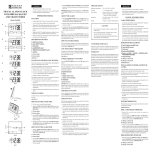
1
9. CBElJETEJIbCTHO 0 ITPPlEMKE
IIpu4eJI HOYHOrO BUneHUll ((hlfirbl~~-jn))
38B O ~ C K O HOMeP
~ ~
IIPU?AaU "OilHblM
Ann 3 ~ c n n y a ~ a u u u .
99@95g--
.
A
.
A a ~ au3rolVsneHun
fl2 . .2J9'?/i
-
1. GENERAL
'd
1
'
The nightfinder sight "Baigysh-SP" (hereinafter
referred to as sight) complete with a sporting carbine type
"Los-4"; "Los-7, "Bars" is designed to enhance the
effectiveness of aiming when firing from a sporting arm
and for search and observation of the higet under conditions of an ambient skylight intensity.
The aiming mechanism allows for accurate varying of the sight position relalive to the weapon barrel
for the sight adiustment.
The range of visibility while viewing through
- the
sight depends o i the ambient skylight intensity, nature of
the objects to be observed, transparency of atmosphere
and on the contrast between the object and background.
The sight is serviceable at a temperature of -10 to
+3joc.
Power to the sight is supplied from a 9 V d.c.
source: batteries "Korund" 6PLF22, "TOSHIBA" 6F22U,
6F22K, 6F22S, "ENERGIZER", "VARTA"6F22.
3. STANDARD EQUIPMENT
The nightfinder
sight
is a soohisti- "Bai~ysh-5P"
-.
cated opto-electronic unit. To ensure its proper operation,
Description
1 . Nightfinder sight "Baigysh-5P"
NEVER:
2 . Socket wrench
-disassemble the sight by yourself;
-feed the sight from power sources of over 9 V;
- operate the sight ill the daytime with the
objective lens open;
- lay the cut-in sight on bright light sources
(lights, head-lamps and the like),
-apply excessive force while operating the sight.
3. Spacer
-.-
1
!
I
I
I
4. Package
5. User Manual
I
Note. The sight comes on sale willlout battery.
4. SAFETY PRECAUTIONS
Make sure that the sight is securely ~nountedon
the arm, otherwise it may cause damage to you.
2. SPECIFICATIONS
Range of acquisition of a large
target (like elk) at 114 Moon
night, rn, min
Magnjfication
Angle of field of vision
Diopter setting range, dptr
Time of operation from one battery "Korund" 6PLF22 at a temperature of 20" C, h, min
Mass of the sight, kg, max
Overall dimensions, mm, max
Quantity
400
2.0"
7"
Avoid excessive compression of the eyeshield
when aiming. The eyeshield may be compressed until a
clear margin of field of vision is obtained.
5. CONSTRUCTION
&J
__I
6
1.5
420x105~70
The sight consists of objective lens I (Fig. I) with
the system of aiming mark displacement, body 2 with
support to fix the siglit on an arm, eyepiece 4 and power
supply unit 7.
Body 2 houses the image converter tube and
toggle switch to turn the sight onloff. Mounted on the
right side of the body is knob 3 of the aiming mark
brightness control.
On the body of objective lens I there are two
dials of the aiming mark displacement system, closed
with covers 8, 9 and allowing to match the arm aiming
axis and the mark in two mutually perpendicular planes.
To protect optical parts against damage the
objective lens and the eyepiece are closed with covers 10
and 6. Provided in the centre of cover 10 is a hole allowing observation under conditions of increased illumination (in the dusk).
6. PREPARATION FOR OPERATION
6.1. Fitting in the battery
To fit in the battery, release the power unit cover
by turning the cover handwheel 90" counterclockwise
and remove the cover (Fig. 2). Fit in the battery observing proper polarity. Install spacer. Close the cover.
Check to see that the power unit body slots match with
the locking spring position. Turn the cover liandwlieel
90" clockwise; make sure that the cover is securely fixed.
6.2. Adjusting the eyepiece according to the observer's eye
Check to see that the objective lens is closed with
the cover. Turn on the sight by placing the switch to the
"0" position (Fig. 3).
viewing through the eyepiece, make sure that the
screen with central aiming mark (Fig. 4) starts to illuminate. With the help of knob 3 (see Fig. 1) adjust the
brightest luminescence of the aiming mark. Rotating
eyepiece 4, obtain a sharp image of the object under
observation. While using the sight as an ordinary
observation device. to make observation more comfor!able you can switch off the aiming mark by placing the
brightness col~trolk~mb3 to the extreme position. Turn
off the sight.
6.3. Mountir~gthe sight on the arm
Mount the sight on the arm with a fitting point of
a dovetail type (carbines type "Los 4, 7") directly. For
this purpose, mount the sight on the arm and securely
tighten u p the screws with the wrench (Fig. 5).
6.4. Boresight zeroing on the arm
For better results adjust the sight in the daytime
or in the dusk.
Set the arm on adjustment device without sight
mounted. Aim the arm by non-optical sight at an aiming
point on the target located at the distance corresponding
to that of direct fire for this type of weapon.
Mount the sight on the arm as directed in p. 6.3.
Make sure that the objective lens is closed with
the cover. '
Turn on the sight and check to see that the vertex
of the aiming mark angle aligns with the same aiming
point as viewed through non-optical sight.
In the case the vertex of the aiming mark angle
does not align with the aiming point, align them with the
help of-the aiming mechanism as follows.
Undo covers 8 and 9 (see Fig. 1) and making use
of the dials allowing to displace the aiming mark in mutually perpendicular planes align the angle vertex with
the aiming point.
Remove the arm with the sight mounted on it
from the adjustment device, and accurately and uniformly
aiming through the sight at the aiming point, take four
shots.
Assess the accuracy of hits and middle point of
strike.
In the case the accuracy of hits is satisfactory, i.e.
not worsetkan that of fire with non-optical sight for
Ik-objective lens; 2-body; 3- aiming mark brightness
control knob; 4--eyepiece; 5--eyeshield; 6, 10--removable
protective covers; 7-power supply unit; 8, 9--covers
Fig. 1
the given type of weapon, estimate the location of the
middle point of strike relative to the test point (the latter
may either align with the aiming point or locate over it at
certain distance depeuding on type of weapon).
The middle point of strike should align with the
test point or deviate from it on 5' at most, this value corresponding to 15 cm for the distance of 100 m to the
target or 7.5 cm for the distance of 50 m.
In the case the deviation of the middle point of
strike from the test point exceeds 5', it is necessary to correct the boresight zeroing with the help of the aiming mechanism following the above sequence.
Take another four shots and, if necessary, fulfil
additional zeroing of the sight.
7. OPERATION PROCEDURE
Mount the sight onto the arm on the same fitting
point as when zeroing it.
While operating the sight in the daytime and in
the early dusk, see that the objective lens is closed with
the cover.
At night and in the late dusk the objective lens
should be fully open.
Successful observation and shooting with the
help of the sight depend on experience in observation as
the picture contrast and the colouring of the terrain and
the target viewed through the sight greatly differ from
those observed by naked eye.
To assure fatigue-free viewing and accurate fire
with the sight at night, it is helpful to thoroughly investigate the locality during the daylight hours.
Dark points and spots viewed in the sight field of
vision originate from the image converter tube operation
and are not considered to he a malfunction.
8. MAINTENANCE AND STORAGE KIJLES
Keep the sight clean and protect it from sharp
impacts and moisture.
Remove dust from the outer optical surfaces with
a dry cloth. To remove greasy spots use a cloth moistened
with an alcohol or ether.
The sight is to be stored in the case in a dry and
heated room.
I
I