1
SAFETY PRECAUTIONS
(Read these precautions before using this product.)
Before using this product, please read this manual and the relevant manuals carefully and pay full attention
to safety to handle the product correctly.
In this manual, the safety precautions are classified into two levels: "
WARNING" and "
CAUTION".
WARNING
Indicates that incorrect handling may cause hazardous conditions,
resulting in death or severe injury.
CAUTION
Indicates that incorrect handling may cause hazardous conditions,
resulting in minor or moderate injury or property damage.
Under some circumstances, failure to observe the precautions given under "
CAUTION" may lead to
serious consequences. Observe the precautions of both levels because they are important for personal and
system safety.
Make sure that the end users read this manual and then keep the manual in a safe place for future
reference.
A-1
[Design Precautions]
WARNING
● Configure safety circuits external to the programmable controller to ensure that the entire system
operates safely even when a fault occurs in the external power supply or the programmable
controller. Incorrect output or malfunction due to a communication failure may result in an accident.
(1) Emergency stop circuits, protection circuits, and protective interlock circuits for conflicting
operations (such as forward/reverse rotations or upper/lower limit positioning) must be
configured external to the programmable controller.
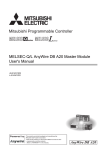
(2) When the programmable controller detects the following problems, it will stop calculation and
turn off all outputs in the case of (a).
In the case of (b), it will hold or turn off all outputs according to the parameter setting.
Note that the A series module will turn off the output in either of cases (a) and (b).
(a) The power supply module has over current
protection equipment and over voltage
protection equipment.
(b) The CPU module self-diagnosis functions, such
as the watchdog timer error, detect problems.
Q series module
A series module
Output OFF
Output OFF
Hold or turn off all output
according to the parameter
setting.
Output OFF
Also, all outputs may be turned on if an error occurs in a part, such as an I/O control part, where
the CPU module cannot detect any error. To ensure safety operation in such a case, provide a
safety mechanism or a fail-safe circuit external to the programmable controller. For a fail-safe
circuit example, refer to the MELSEC-L CPU Module User's Manual (Hardware Design,
Maintenance and Inspection).
(3) Outputs may remain on or off due to a failure of a component such as a transistor in an output
circuit. Configure an external circuit for monitoring output signals that could cause a serious
accident. Configure an external circuit for monitoring output signals that could cause a serious
accident.
A-2
[Design Precautions]
WARNING
● In an output module, when a load current exceeding the rated current or an overcurrent caused by a
load short-circuit flows for a long time, it may cause smoke and fire. To prevent this, configure an
external safety circuit, such as a fuse.
● Configure a circuit so that the programmable controller is turned on first and then the external power
supply.
If the external power supply is turned on first, an accident may occur due to an incorrect output or
malfunction.
● In the case of a communication failure in the network, the status of the error station will be as follows:
Check the communication status information and configure an interlock circuit in the sequence
program to ensure that the entire system will operate safely.
Incorrect output or malfunction due to a communication failure may result in an accident.
(1) All inputs from remote I/O stations are turned off.
(2) All outputs from remote I/O stations are turned off.
● When connecting a peripheral with the CPU module or connecting an external device, such as a
personal computer, with an intelligent function module to modify data of a running programmable
controller, configure an interlock circuit in the program to ensure that the entire system will always
operate safely.
For other forms of control (such as program modification or operating status change) of a running
programmable controller, read the relevant manuals carefully and ensure that the operation is safe
before proceeding.
Especially, when a remote programmable controller is controlled by an external device, immediate
action cannot be taken if a problem occurs in the programmable controller due to a communication
failure.
To prevent this, configure an interlock circuit in the program, and determine corrective actions to be
taken between the external device and CPU module in case of a communication failure.
CAUTION
● Use the programmable controller in an environment that meets the general specifications in a
product manual.
Failure to do so may result in electric shock, fire, malfunction, or damage to or deterioration of the
product.
● Do not install the control lines or communication cables together with the main circuit lines or power
cables.
Keep a distance of 100mm or more between them.
Failure to do so may result in malfunction due to noise.
● During control of an inductive load such as a lamp, heater, or solenoid valve through an output
module, a large current (approximately ten times greater than normal) may flow when the output is
turned from off to on. Therefore, use a module that has a sufficient current rating.
A-3
[Installation Precautions]
CAUTION
● Connectors for external devices must be crimped with the tool specified by the manufacturer, or must
be correctly soldered. Securely connect the connector to the module.
● Use the programmable controller in an environment that meets the general specifications in the
QCPU User's Manual (Hardware Design, Maintenance and Inspection).
Failure to do so may result in electric shock, fire, malfunction, or damage to or deterioration of the
product.
● To mount the module, while pressing the module mounting lever located in the lower part of the
module, fully insert the module fixing projection(s) into the hole(s) in the base unit and press the
module until it snaps into place.
Incorrect interconnection may cause malfunction, failure, or drop of the module.
When using the programmable controller in an environment of frequent vibrations, fix the module
with a screw.
Tighten the screws within the specified torque range.
Undertightening can cause drop of the screw, short circuit, or malfunction.
Overtightening can damage the screw and/or module, resulting in drop, short circuit, or malfunction.
● When using an extension cable, connect it to the extension cable connector of the base unit
securely.
Check the connection for looseness.
Poor contact may cause incorrect input or output.
● Shut off the external power supply (all phases) used in the system before cleaning the module.
Failure to do so may result in damage to the product.
A module can be replaced online (while power is on) on any MELSECNET/H remote I/O station or in
the system where a CPU module supporting the online module change function is used.
Note that there are restrictions on the modules that can be replaced online, and each module has its
predetermined replacement procedure.
For details, refer to the QCPU User's Manual (Hardware Design, Maintenance and Inspection) and the
online module change in the manual for the module corresponding the online module change.
● Do not directly touch any conductive parts of the module.
Doing so can cause malfunction or failure of the module.
[Wiring Precautions]
WARNING
● Shut off the external power supply (all phases) used in the system before wiring.
Failure to do so may result in electric shock or damage to the product.
● After wiring, attach the included terminal cover to the module before turning it on for operation.
Failure to do so may result in electric shock.
A-4
[Wiring Precautions]
CAUTION
● Individually ground the FG terminal of the programmable controller with a ground resistance of 100
or less. Failure to do so may result in electric shock or malfunction.
● Check the rated voltage and terminal layout before wiring to the module, and connect the cables
correctly.
Connecting a power supply with a different voltage rating or incorrect wiring may cause a fire or
failure.
● Connectors for external devices must be crimped or pressed with the tool specified by the
manufacturer, or must be correctly soldered.
Incomplete connections may cause short circuit, fire, or malfunction.
● Tighten the screws within the specified torque range.
Undertightening can cause short circuit, fire, or malfunction.
Overtightening can damage the screw and/or module, resulting in drop, short circuit, or malfunction.
● Tighten any unused terminal screws within the specified torque range (42 to 50N•cm).
Failure to do so may cause a short circuit due to contact with a solderless terminal.
● Use applicable solderless terminals and tighten them within the specified torque range.
If any spade solderless terminal is used, it may be disconnected when a terminal screw comes
loose, resulting in failure.
● Prevent foreign matter such as dust or wire chips from entering the module.
Such foreign matter can cause a fire, failure, or malfunction.
● A protective film is attached to the top of the module to prevent foreign matter, such as wire chips,
from entering the module during wiring.
Do not remove the film during wiring.
Remove it for heat dissipation before system operation.
● Place the cables in a duct or clamp them.
If not, dangling cable may swing or inadvertently be pulled, resulting in damage to the module or
cables or malfunction due to poor contact.
● Do not install the control lines together with the communication cables.
Failure to do so may result in malfunction due to noise.
● When disconnecting the communication cable or power cable from the module, do not pull the cable
by the cable part.
For the cable with connector, hold the connector part of the cable. Loosen the screws of a cable
without a connector before disconnecting the cable. Failure to do so may result in damage to the
module or cable or malfunction due to poor contact.
A-5
[Startup and Maintenance Precautions]
WARNING
● Do not touch any terminal or connector while power is on.
Failure to do so may result in electric shock.
● Shut off the external power supply (all phases) used in the system before cleaning the module or
retightening the terminal screws or module fixing screws.
Failure to do so may result in electric shock.
Undertightening can cause drop of the screw, short circuit, or malfunction.
Overtightening can damage the screw and/or module, resulting in drop, short circuit, or malfunction.
CAUTION
● Before performing online operations (especially, program modification, forced output, and operating
status change) for the running CPU module from the peripheral device connected, read relevant
manuals carefully and ensure the safety.
Improper operation may damage machines or cause accidents.
● Do not disassemble or modify the module.
Doing so may cause failure, malfunction, injury, or a fire.
● Use any radio communication device such as a cellular phone or PHS (Personal Handy-phone
System) more than 25cm away in all directions from the programmable controller.
Failure to do so may cause malfunction.
● Do not drop or apply strong shock to the module.
Doing so may damage the module.
● Shut off the external power supply (all phases) used in the system before mounting or removing a
module.
Failure to do so may cause the module to fail or malfunction.
● After the first use of the product, do not mount/remove the module to/from the base unit more than
50 times (IEC 61131-2 compliant) respectively.
Exceeding the limit may cause malfunction.
● Before handling the module, touch a conducting object such as a grounded metal to discharge the
static electricity from the human body.
Failure to do so may cause the module to fail or malfunction.
[Disposal Precautions]
CAUTION
● When disposing of this product, treat it as industrial waste.
A-6
CONDITIONS OF USE FOR THE PRODUCT
(1) Mitsubishi programmable controller ("the PRODUCT") shall be used in conditions;
i) where any problem, fault or failure occurring in the PRODUCT, if any, shall not lead to any major
or serious accident; and
ii) where the backup and fail-safe function are systematically or automatically provided outside of
the PRODUCT for the case of any problem, fault or failure occurring in the PRODUCT.
(2) The PRODUCT has been designed and manufactured for the purpose of being used in general
industries.
MITSUBISHI SHALL HAVE NO RESPONSIBILITY OR LIABILITY (INCLUDING, BUT NOT
LIMITED TO ANY AND ALL RESPONSIBILITY OR LIABILITY BASED ON CONTRACT,
WARRANTY, TORT, PRODUCT LIABILITY) FOR ANY INJURY OR DEATH TO PERSONS OR
LOSS OR DAMAGE TO PROPERTY CAUSED BY the PRODUCT THAT ARE OPERATED OR
USED IN APPLICATION NOT INTENDED OR EXCLUDED BY INSTRUCTIONS, PRECAUTIONS,
OR WARNING CONTAINED IN MITSUBISHI'S USER, INSTRUCTION AND/OR SAFETY
MANUALS, TECHNICAL BULLETINS AND GUIDELINES FOR the PRODUCT.
("Prohibited Application")
Prohibited Applications include, but not limited to, the use of the PRODUCT in;
• Nuclear Power Plants and any other power plants operated by Power companies, and/or any
other cases in which the public could be affected if any problem or fault occurs in the PRODUCT.
• Railway companies or Public service purposes, and/or any other cases in which establishment of
a special quality assurance system is required by the Purchaser or End User.
• Aircraft or Aerospace, Medical applications, Train equipment, transport equipment such as
Elevator and Escalator, Incineration and Fuel devices, Vehicles, Manned transportation,
Equipment for Recreation and Amusement, and Safety devices, handling of Nuclear or
Hazardous Materials or Chemicals, Mining and Drilling, and/or other applications where there is a
significant risk of injury to the public or property.
Notwithstanding the above, restrictions Mitsubishi may in its sole discretion, authorize use of the
PRODUCT in one or more of the Prohibited Applications, provided that the usage of the PRODUCT
is limited only for the specific applications agreed to by Mitsubishi and provided further that no
special quality assurance or fail-safe, redundant or other safety features which exceed the general
specifications of the PRODUCTs are required. For details, please contact the Mitsubishi
representative in your region.
A-7
REVISIONS
* The handbook number is given on the bottom left of the back cover.
Print Date
* Handbook Number
January, 2013
L(NA)08263ENG-A
Revision
First edition
Japanese Handbook Version L08249-A
This handbook confers no industrial property rights or any rights of any other kind, nor does it confer any patent licenses.
Mitsubishi Electric Corporation cannot be held responsible for any problems involving industrial property rights which may
occur as a result of using the contents noted in this handbook.
© 2013 MITSUBISHI ELECTRIC CORPORATION
A-8
Memo
A-9
CONTENTS
SAFETY PRECAUTIONS ................................................................................................................................A - 1
CONDITIONS OF USE FOR THE PRODUCT .................................................................................................A - 7
REVISIONS ......................................................................................................................................................A - 8
CONTENTS ...................................................................................................................................................A - 10
GENERIC TERMS AND ABBREVIATIONS ...................................................................................................A - 13
CHAPTER 1 INTRODUCTION
1 - 1 to 1 - 2
1.1
Replacement with AnyWire DB A20 ................................................................................................ 1 - 1
1.2
Precautions for Replacement .......................................................................................................... 1 - 2
1.3
Features of AnyWire DB A20 ........................................................................................................... 1 - 2
CHAPTER 2 PERFORMANCE SPECIFICATIONS COMPARISONS
2 - 1 to 2 - 4
2.1
Performance Specifications Comparison of MELSEC-I/OLINK and AnyWire DB A20 .................... 2 - 1
2.2
Wiring for AnyWire DB A20 ............................................................................................................. 2 - 3
2.2.1
2.2.2
2.2.3
Transmission distance .............................................................................................................. 2 - 3
Terminator connection .............................................................................................................. 2 - 3
Branch of transmission lines (transmission distance: 1km) ...................................................... 2 - 4
CHAPTER 3 FUNCTIONAL COMPARISONS
3 - 1 to 3 - 3
3.1
Functional Comparisons of MELSEC-I/OLINK and AnyWire DB A20 ............................................. 3 - 1
3.2
Master Module Switch Comparisons ............................................................................................... 3 - 2
CHAPTER 4 REPLACING THE MASTER MODULE
4.1
List of Alternative Master Module Models ........................................................................................ 4 - 1
CHAPTER 5 PROGRAMS COMPARISONS
5.1
4 - 1 to 4 - 2
5 - 1 to 5 - 6
I/O Signals ....................................................................................................................................... 5 - 1
5.1.1
5.1.2
MELSEC-I/OLINK ..................................................................................................................... 5 - 1
AnyWire DB A20 (QJ51AW12D2) ............................................................................................ 5 - 3
CHAPTER 6 REPLACING THE I/O MODULES
6 - 1 to 6 - 40
6.1
List of Alternative I/O Module Models .............................................................................................. 6 - 1
6.2
I/O Module Specifications Comparisons .......................................................................................... 6 - 6
6.2.1
6.2.2
6.2.3
6.3
A - 10
Input module specifications comparisons ................................................................................. 6 - 6
Output module specifications .................................................................................................. 6 - 12
I/O module specifications comparisons .................................................................................. 6 - 18
Applicable Crimping Terminal ........................................................................................................ 6 - 40
CHAPTER 7 EXTERNAL DIMENSIONS
7 - 1 to 7 - 4
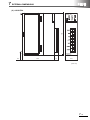
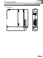
7.1
MELSEC-I/OLINK External Dimensions .......................................................................................... 7 - 1
7.2
AnyWire DB A20 External Dimensions ............................................................................................ 7 - 4
APPENDICES
APPX- 1 to APPX - 2
Appendix 1 Relevant Manuals ...........................................................................................................APPX - 1
Appendix 1.1 Replacement handbooks .........................................................................................APPX - 1
Appendix 1.2 MELSEC-I/OLINK ....................................................................................................APPX - 2
Appendix 1.3 AnyWire DB A20 .....................................................................................................APPX - 2
A - 11
● For the products shown in handbooks for transition, catalogues, and transition examples, refer to the
manuals for the relevant products and check the detailed specifications, precautions for use, and
restrictions before replacement.
For the products manufactured by Mitsubishi Electric Engineering Co., Ltd., Mitsubishi Electric System
& Service Co., Ltd., and other companies, refer to the catalogue for each product and check the
detailed specifications, precautions for use, and restrictions before use.
The manuals and catalogues for our products, products manufactured by Mitsubishi Electric
Engineering Co., Ltd., and Mitsubishi Electric System & Service Co., Ltd. are shown in Appendix of
each handbook for transition.
● Products shown in this handbook are subject to change without notice.
A - 12
GENERIC TERMS AND ABBREVIATIONS
Unless otherwise specified, this handbook uses the following generic terms and abbreviations.
Generic term/abbreviation
Series
A series
AnS series
A/AnS series
QnA series
QnAS series
QnA/QnAS series
A/AnS/QnA/QnAS series
Q series
L series
CPU module type
CPU module
Basic model QCPU
High Performance model QCPU
Process CPU
Redundant CPU
Description
The abbreviation for large types of Mitsubishi MELSEC-A series programmable
controllers
The abbreviation for compact types of Mitsubishi MELSEC-A series programmable
controllers
A generic term for A series and AnS series
The abbreviation for large types of Mitsubishi MELSEC-QnA series programmable
controllers
The abbreviation for compact types of Mitsubishi MELSEC-QnA series programmable
controllers
A generic term for QnA series and QnAS series
A generic term for A series, AnS series, QnA series, and QnAS series
The abbreviation for Mitsubishi MELSEC-Q series programmable controllers
The abbreviation for Mitsubishi MELSEC-L series programmable controllers
A generic term for A series, AnS series, QnA series, QnAS series, Q series, and L
series CPU modules
A generic term for the Q00JCPU, Q00CPU, and Q01CPU
A generic term for the Q02CPU, Q02HCPU, Q06HCPU, Q12HCPU, and Q25HCPU
*This handbook mainly explains the Q02CPU, Q02HCPU, Q06HCPU, and Q12HCPU.
A generic term for the Q02PHCPU, Q06PHCPU, Q12PHCPU, and Q25PHCPU
A generic term for the Q12PRHCPU and Q25PRHCPU
A generic term for the Q00UJCPU, Q00UCPU, Q01UCPU, Q02UCPU, Q03UDCPU,
Q04UDHCPU, Q06UDHCPU, Q10UDHCPU, Q13UDHCPU, Q20UDHCPU,
Q26UDHCPU, Q03UDECPU, Q04UDEHCPU, Q06UDEHCPU, Q10UDEHCPU,
Q13UDEHCPU, Q20UDEHCPU, Q26UDEHCPU, Q50UDEHCPU, and
Q100UDEHCPU
Universal model QCPU
* This handbook mainly explains about the Q00UJCPU, Q00UCPU, Q01UCPU,
Q02UCPU, Q03UDCPU, Q04UDHCPU, and Q06UDHCPU, which can replace the
AnS/QnAS series.
The specifications and functions of the Q10UDEHCPU to Q100UDEHCPU are the
same as those of the modules described above, although the program and memory
LCPU
CPU module model
ACPU
AnSCPU
AnNCPU
AnACPU
AnUCPU
AnUS(H)CPU
A/AnSCPU
AnN/AnACPU
AnN/AnA/AnSCPU
QnACPU
QnASCPU
capacities increase.
A generic term for the L02CPU, L02CPU-P, L26CPU-BT, and L26CPU-PBT
A generic term for MELSEC-A series CPU modules
A generic term for MELSEC-AnS series CPU modules
A generic term for the A1NCPU, A1NCPUP21/R21, A1NCPUP21-S3, A2NCPU,
A2NCPU-S1, A2NCPUP21/R21, A2NCPUP21/R21-S1, A2NCPUP21-S3(S4),
A3NCPU, A3NCPUP21/R21, and A3NCPUP21-S3
A generic term for the A2ACPU, A2ACPU-S1, A3ACPU, A2ACPUP21/R21,
A2ACPUP21/R21-S1, and A3ACPUP21/R21
A generic term for the A2UCPU, A2UCPU-S1, A3UCPU, and A4UCPU
A generic term for the A2USCPU, A2USCPU-S1, A2USHCPU-S1
A generic term for MELSEC-A series and -AnS series CPU modules
A generic term for the AnNCPU and AnACPU
A generic term for the AnNCPU, AnACPU, and AnSCPU
A generic term for MELSEC-QnA series CPU modules
A generic term for MELSEC-QnAS series CPU modules
A - 13
Generic term/abbreviation
QnA/QnASCPU
A/AnS/QnA/QnASCPU
QCPU
LCPU
A - 14
Description
A generic term for MELSEC-QnA series and -QnAS series CPU modules
A generic term for MELSEC-A series, -AnS series, -QnA series, and -QnAS series CPU
modules
A generic term for MELSEC-Q series CPU modules
A generic term for MELSEC-L series CPU modules
1
INTRODUCTION
1
INTRODUCTION
1
1.1 Replacement with AnyWire DB A20
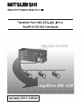
The MELSEC-Q and L series do not have an MELSEC-I/OLINK master module. Therefore, the
alternatives are the AnyWire DB A20 and the CC-Link/LT. Features for replacement are listed in the
following table.
Replacing MELSEC-I/OLINK with AnyWire DB A20 or CC-Link/LT
: Compatible, ×: Not compatible
Replacement with AnyWire DB A20
Item
Replacement with CC-Link/LT
(MELSEC-Q series)
Compatibility
Description
The existing I/OLINK external power supply
can be used.
External power supply
(MELSEC-Q/L series)
Compatibility
×
Description
A power supply adapter is necessary.
Connection type
T-branch system, or tree branch system
Connection cable
The existing I/OLINK cables can be used.
I/O module type
4, 8, or 16 points
Input module/Output module/I/O combined
module
2, 4, or 8 points
Input module/Output module/I/O combined
module
The master module occupies 32 points.
The I/O module address becomes the
specified device by the FROM/TO instruction.
XY address of the master module becomes
XY address of the I/O module.
Needless to change address (up to 64 points)
Programming
×
T-branch system
×
New cables must be installed.
Point
AnyWire products are not available in some countries. For details, please consult your local Mitsubishi
representative.
This transition handbook explains replacement of the MELSEC-I/OLINK with the AnyWire DB A20.
For replacement with the CC-Link/LT, refer to the following transition handbook.
Transition from MELSEC-I/OLINK to CC-Link/LT Handbook
1-1
1
INTRODUCTION
1.2 Precautions for Replacement
(1) Before replacing MELSEC-I/OLINK with AnyWire DB A20, refer to the manuals for each
AnyWire DB A20 module, and check the functions, specifications, and how to use the
modules.
(2) After replacing MELSEC-I/OLINK with AnyWire DB A20, check the operation of the entire
system before starting the actual operation.
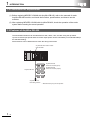
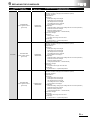
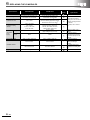
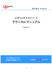
1.3 Features of AnyWire DB A20
The transmission distance can be selected from 50m, 200m, 1km, and 3km using the dip switch.
Up to 512 remote input points and 512 remote output points can be controlled by one QJ51AW12D2 (in
the standard setting).
Disconnections can be detected even when the wiring is branched.
AnyWire DB A20 master module
QJ51AW12D2
AnyWire DB A20
remote I/O module (input)*
AnyWire DB A20
remote I/O module (output)*
AnyWire DB A20
AnyWire DB A20
terminating resistor*
1-2
*: Manufactured by Anywire Corporation
2
PERFORMANCE SPECIFICATIONS COMPARISONS
2
PERFORMANCE SPECIFICATIONS
COMPARISONS
2
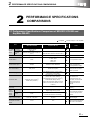
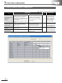
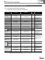
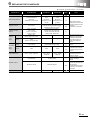
2.1 Performance Specifications Comparison of MELSEC-I/OLINK and
AnyWire DB A20
: Compatible,
Specifications
Item
Max. number of
Per single link stations
master
Max. number of
station
control I/O
points
Link scan time
Overall distance
Communication speed
Error control method
Network Topology
: Partially changed, ×: Not compatible
Com-
MELSEC-I/OLINK
AnyWire DB A20
16 stations
(1 station 4 points)
128 stations
128 points
(when the same number is used on X
and Y)
1024 points
(when the same number is used on X and Y)
Approx. 5.4ms
2.7ms (for 128 points)*1
200m
125kHz: 50m
31.3kHz: 200m
7.8kHz: 1km
2kHz: 3km
38.4kbps
125kHz/31.3kHz/7.8kHz/2kHz
Parity check
Double-check system
Bus (T-branch available)
Bus (Multidrop system, T-branch system,
star system, or tree system)
patibility
Select the speed based on the
existing overall distance.
1kHz is equivalent to 1kbps.
The error control method is
different, but an error check
function is provided.
Crimping terminals can be
used. However, the
communication lines and
power lines connected to the
master module must be
processed to connect to
terminals.
(VCTF, VCF 0.75 to 1.25mm2),
Twisted pair cable (0.75mm2),
Cabtire cable (0.75mm2)
General-purpose wire (0.75 to 1.25mm2),
Dedicated flat cable (0.75mm2),
(When the transmission distance exceeds
200m, use wires with a diameter of 0.9 to
1.25mm2.)
Terminating resistor
(terminator)
ment
1kHz is equivalent to 1kbps.
General-purpose 2-/4-wire cable
Connection cable
Precautions for replace-
Required
Voltage
21.6 to 27.6VDC
24VDC +15 to -10% (21.6 to 27.6VDC)
Ripple voltage 0.5Vp-p or less
Current
0.09A
0.5A (When 128 slave modules are connected
and the load current is not included)
Number of occupied I/O
points of master module
16, 32, 48, or 64 points
32 points
The program and parameters
must be changed.
Internal current
consumption of master
module
0.115A
0.5A
Internal current consumption of
5VDC must be recalculated.
External
power
supply to
master
module
×
A terminating resistor is
necessary.
Not required
Because the external power
supply current has increased,
the current capacity must be
reviewed.
2-1
2
PERFORMANCE SPECIFICATIONS COMPARISONS
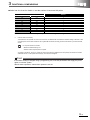
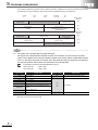
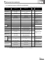
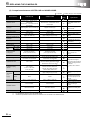
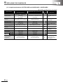
*1
The transmission cycle time of AnyWire DB A20 (QJ51AW12D2) differs by the number of transmission points setting or the
transmission clock. For details, refer to the following table.
Max. number of transmission
points setting
2-2
Transmission cycle time (ms)
125kHz
31.3kHz
7.8kHz
2kHz
(50m)
(200m)
(1km)
(3km)
24.8
64 points (32 points × 2)
0.42
1.7
6.8
128 points (64 points × 2)
0.7
2.7
10.9
40.7
256 points (128 points × 2)
1.2
4.8
19.1
72.4
384 points (192 points × 2)
1.7
6.8
27.3
104.2
512 points (256 points × 2)
2.2
8.9
35.5
135.9
640 points (320 points × 2)
2.7
10.9
43.6
167.6
768 points (384 points × 2)
3.2
13.0
51.8
199.4
896 points (448 points × 2)
3.8
15.0
60.0
231.1
1024 points (512 points × 2)
4.3
17.1
68.2
262.9
2048 points (1024 points × 2)
8.4
33.4
133.8
516.8
2
PERFORMANCE SPECIFICATIONS COMPARISONS
2.2 Wiring for AnyWire DB A20
2.2.1 Transmission distance
Item
Specifications
Transmission clock
Max. transmission distance
(total length)
Number of connectable modules
*1
125kHz*1
31.3kHz
7.8kHz
2kHz
50m
200m
1km
3km
Up to 128
Up to 128
Up to 128
Up to 32*2
When the transmission clock is set to 125 kHz, use the product under the following conditions.
• External power supply voltage range: 21.6VDC to 25.2VDC
• Operating ambient temperature: 0 to 50°C
*2
Up to 64 modules can be connected within 2km.
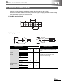
2.2.2 Terminator connection
To ensure more stable transmission, connect the terminating resistor (AT2 manufactured by Anywire
Corporation) at the end of the transmission line.
Terminating unit
Basic
Important
Connect a terminating unit at the end of a line for one master
module.
Transmission distance 50m (total length)
200m (total length)
1km (total length)
3km (total length)
The setting applies to all the transmission speeds.
2-3
2
PERFORMANCE SPECIFICATIONS COMPARISONS
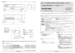
2.2.3 Branch of transmission lines (transmission distance: 1km)
AnyWire
at the end
Branch line:
200m
Main line: 500m
Branch line: 300m
Important
Connect one terminating unit at the end of a branch line that is
200m or longer.
Contact us if more than two branch lines are 200m or longer.
Total length
Basic
A
B
The total length of the transmission distance for the AnyWire DB A20 can be
calculated from A + B. Note that the total length should not exceed the maximum
transmission distance set for the system to branch lines.
2-4
3
FUNCTIONAL COMPARISONS
3
FUNCTIONAL COMPARISONS
3
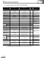
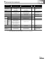
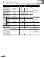
3.1 Functional Comparisons of MELSEC-I/OLINK and AnyWire DB A20
: Compatible,
Item
Specifications
MELSEC-I/OLINK
AnyWire DB A20
Remote station
communication
Communication with up to 16 slave
stations is possible.
Remote station address
I/O information is stored in the buffer
memory.
XY address of the master station becomes The device that data are read from and
the XY address of the remote station
written to the buffer memory by the
module.
FROM/TO instruction will be assigned
to the remote station module address in
the program.
Detection of faulty
station (display)
RAS
function
Others
The LED display (ERROR STATION) on
the master station notifies a user of faulty
stations.
When an error is detected, the CPU
Notification method
module is notified by Fuse blown detection
of the error
(M 9000). External output is also
detection to the
performed from the RUN A/B terminals on
CPU module
the MELSEC-I/OLINK master module.
: Partially changed, ×: Not compatible
Compat-
Precautions for
ibility
replacement
Communication with up to 128 slave
stations is possible.
×
Program change or different
remote station module line
numbers are required
because the concept of the
addresses is different.
The LED display (ALM) on the master
station notifies a user of faulty stations.
An error is notified by the I/O signal
(Xn4: Disconnection detected) from the
AnyWire DB A20 master module. Note,
however, an external output is not
performed from terminals.
Line check
Cable disconnection can be checked by
the ON status of the LEDs on the master
station and slave stations.
Cable disconnection can be checked by
the ON status of the LEDs on the
master station and slave stations.
Error check of
disconnected
station enabled/
disabled setting
If there is a station that is not connected,
the error check can be disabled by setting
the ON LINE STATION switch of the
master station to off.
The master station is provided with a
function to automatically recognize the
number of occupied points and the set
address of the connected station.
Change of the sequence
program is required because
the notifying device differs. If
an external output is required,
an output signal is necessary.
Though the setting method
differs, a station that is not
connected can be detected.
3-1
3
FUNCTIONAL COMPARISONS
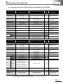
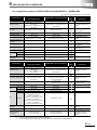
3.2 Master Module Switch Comparisons
: Compatible,
Specifications
Item
MELSEC-I/OLINK
Number of transmission
points setting
(I/OLINK)
The number of occupied points of the master
module is set to 16, 32, 48, or 64 points by
the I/O assignment of the parameter.
The number of occupied points of the master
module becomes the maximum number of
connected points.
Set by parameters and there is no switch
setting.
Operation mode selector
(AnyWire DB A20)
Setting is not required, because the
communication speed and transmission
distance are fixed.
ON LINE STATION
(I/OLINK)
A switch for determining use/not use of
remote I/O module.
SET switch
(AnyWire DB A20)
*1
–
AnyWire DB A20
The number of transmission points of the
slave module is set by the intelligent
function switch setting of PLC Parameter
in GX Developer.*1
Select the transmission distance.
The transmission clock is determined by
the transmission distance setting.
–
A switch to let the master module
automatically recognize the ID (address)
of the slave module.
: Partially changed, ×: Not compatible
Compat-
Precautions for
ibility
replacement
The maximum number of
transmission points setting
method is changed from
setting the I/O assignment of
parameter to intelligent
function switch setting.
Settings are required in
accordance with the number
of connected slave modules
and the overall distance.
Though the setting method
differs, the station to be used
(remote I/O module or slave
module) can be determined.
Switch setting of the QJ51AW12D2 is performed by using PLC Parameter setting in GX Developer.
Enter a value from 0 to 9
in this column.
3-2
3
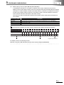
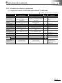
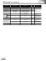
FUNCTIONAL COMPARISONS
Value from 0 to 9 set for "Switch 1" and the number of connected I/O points
Number of connected I/O points
Switch 1
Input
Output
512
512
0
448
448
1
384
384
2
320
320
3
256
256
4
192
192
5
128
128
6
64
64
7
32
32
8
1024
1024
9*1
A to F of "Switch 1" are reserved by the system. Do not change the settings.
*1
Use the value as necessary.
Transmission is also possible for normal use. However, the address after the "Maximum address setting to Number of self
occupied points" of the slave module for the AnyWire DB A20 becomes empty, and the transmission cycle time becomes
slower.
Ex.
For 32-point remote I/O module
• Maximum address setting: 510
• Number of self occupied points: 32 points
According to the above, 510 to 541 points are used as the maximum address that is occupied by the remote I/O module.
Addresses of 541 to 1023 points become empty, and cannot be assigned.
Point
If the switch setting is changed using a programming tool, write the parameters and supply the power
again or reset the system.
Without these operations, transmission points are not set.
3-3
4
REPLACING THE MASTER MODULE
4
REPLACING THE MASTER MODULE
4
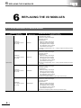
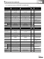
4.1 List of Alternative Master Module Models
MELSEC-I/OLINK
Product
Master module
4-1
Model
AJ51T64
A1SJ51T64
Alternative model for AnyWire DB A20
Model
QJ51AW12D2
Remarks (restrictions)
It is recommended to replace the module with the AnyWire DB
A20. For details, refer to the user's manual for each module.
4
REPLACING THE MASTER MODULE
Memo
4-2
5
PROGRAMS COMPARISONS
5
PROGRAMS COMPARISONS
5
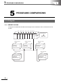
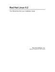
5.1 I/O Signals
5.1.1 MELSEC-I/OLINK
I/O signals of the MELSEC-I/OLINK will be assigned to the addresses of the connected remote I/O
module.
X0
CPU
X20
Y60
Y80
YA0 X/YC0
X1F
X3F
X5F
Y7F
Y9F
YBF X/YFF
A1S
X41
A1S
Y41
A1S
X41
A1S
Y41
A1S
Y41
A1S
Y41
Address C0 to C3
Station
No.0
AJ55TB3-4D
(input module
occupied one station)
Address D4 to DB
Station
No.5
AJ55TB3-8D
(input module
occupied two stations)
5-1
X40
Address C4 to CB
Station
No.1
AJ55TB2-8T
(output module
occupied two stations)
A1S
J51
T64
ON LINE STATION
setting switches
ON: 0 to 6
OFF: 7 to F
Address CC to CF
Station
No.3
AJ55TB32-4DT
(I/O module
occupied one station)
Address D0 to D3
Station
No.4
AJ55TB32-8DT
(I/O module
occupied one station)
5
PROGRAMS COMPARISONS
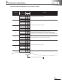
The following table listed addresses for each remote I/O module.
Station No.
of remote
I/O module
Addresses
(Hexadecimal)
Device
Remarks
X
Y
C0
1
0
AJ55TB3-4D (input 4-point module)
2
3
4
1
5
6
7
AJ55TB2-8T (output 8-point module)
8
2
9
A
B
C
D
3
E
AJ55TB32-4DT (input 2-point/output 2-point module)
(A 4-point I/O combined module can be used the first half 2 points
of both of X and Y. The module cannot be used the second half 2 points.
F
D0
4
1
AJ55TB32-8DT (input 4-point/output 4-point module)
2
3
4
5
5
6
7
AJ55TB3-8D (input 8-point module)
8
6
9
A
B
C
The device used is indicated by
.
5-2
5
PROGRAMS COMPARISONS
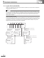
5.1.2 AnyWire DB A20 (QJ51AW12D2)
Details on the addresses when replacing the I/OLINK are explained by using the module configuration
example described in Section 5.1.1.
Point
I/O information of the AnyWire DB A20 are stored in the buffer memory. The device that data are read
from and written to the buffer memory by the FROM/TO instruction will be assigned to the remote station
module address in the program. The program that controls input and output of the I/OLINK remote
station must be changed.
[System configuration example]
In this example, settings are made to match the addresses of the existing I/OLINK. Since the number of
occupied points differ between the existing module and the replacement module, their addresses cannot
be assigned in the same way. The addresses in this replacement module is example. They can be
assigned as desired according to the system configuration.
CPU
X0
X20
X40
Y60
Y80
YA0 X/YC0
X1F
X3F
X5F
Y7F
Y9F
YBF X/YDF
QX41 QY41 QX41 QY41 QY41 QY41
Buffer memory address:
100H (bit 0 to bit 3)
Switch setting: 0
A20SB-04U
(input module)
Buffer memory address:
102H (bit 0 to bit 3)
Switch setting: 32
A20SB-08UD
(input module)
5-3
QJ51
AW12D2
Buffer memory address:
1100H (bit 4 to bit 11)
Switch setting: 4
A20PB-08U
(output module)
Input:
Buffer memory address: 101H (bit 0 to bit 7)
Switch setting: 16
Output:
Buffer memory address: 1101H (bit 0 to bit 7)
Switch setting: 16
A20XB-16UD
(I/O module)
Input:
Buffer memory address: 101H (bit 8 to bit 15)
Switch setting: 24
Output:
Buffer memory address: 1101H (bit 8 to bit 15)
Switch setting: 24
A20XB-16UD
(I/O module)
5
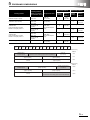
PROGRAMS COMPARISONS
Input side address
Existing address
Existing module
(Refer to configura-
Replaced module
AJ55TB3-4D (input 4 points)
XC0 to XC3
A20SB-04U
(input 4 points)
AJ55TB2-8T (input 8 points)
XC4 to XCB
A20PB-08U
(input 8 points)
AJ55TB32-4DT
(input 2 points/output 2 points)
Number of occupied points is 4.
XD0 to XD3
AJ55TB3-8D (input 8 points)
Bit
15
Bit
14
Bit
13
Bit
12
Bit
11
Bit
10
Bit
9
Bit
8
Bit
7
Bit
6
–
101H
–
101H
1101H
bit 0 to bit 7
–
bit 8 to bit 15
1101H
24
102H
Bit
1
bit 8 to bit 15
–
bit 0 to bit 7
Bit
2
1100H
bit 4 to bit 11
16
–
Bit
3
address
4
–
Bit
4
memory
setting
bit 0 to bit 7
24
Buffer
Switch
bit 0 to bit 3
32
Bit
5
Output side address
100H
16
A20SB-08UD
(input 4 points)
XD4 to XDB
address
–
A20XB-16UD
(input 8 points/output 8
points)
YD0 to YD3
(YCC to YCF are
occupied.)
memory
0
A20XB-16UD
(input 8 points/output 8
points)
YCC to YCD
(YCC to YCF are
occupied.)
AJ55TB32-8DT
(input 4 points/output 4 points)
Number of occupied points is 4.
Switch
setting
tion in Section 5.1.1.)
XCC to XCD
(XCC to XCF are
occupied.)
Buffer
Bit
0
Buffer memory
address
Unused due to
fractional points
Unused
(used area for the existing output module AJ55TB2-8T)
A20XB-16UD (replacement area for AJ55TB32-8DT)
(input: 8 points)
Unused
A20SB-04U
(replacement area for AJ55TB3-4D)
(input: 4 points)
100H
A20XB-16UD (replacement area for AJ55TB32-4DT)
(input: 8 points)
101H
A20XB-08UD (replacement area for AJ55TB32-8D)
(input: 8 points)
102H
Buffer memory
address
Unused (used area for the
existing input module
AJ55TB3-40)
1100H
A20XB-16UD (replacement area for AJ55TB32-8DT)
(output: 8 points)
A20XB-16UD (replacement area for AJ55TB32-4DT)
(output: 8 points)
1101H
Unused
Unused
(used area for the existing input module AJ55TB32-8D)
1102H
Unused due to
fractional points
A20PB-08U (replacement area for AJ55TB2-8T)
(output: 8 points)
5-4
5
PROGRAMS COMPARISONS
*
The XY address specified by the buffer memory read/write instruction "FROM/TO" becomes the XY address in the program.
The following shows the XY address of each module when the FROM/TO instruction is programmed.
FROM
TO
Unused due to
fractional points
H0C
H0C
H1100
H100
K4X1000
K4Y1000
Unused
(used area for the existing output module AJ55TB2-8T)
A20XB-16UD (input: 8 points)
X1018 to X101F
K3
K3
Buffer memory
address
A20SB-04U (input: 4 points)
X1000 to X1003
A20XB-16UD (input: 8 points)
X1010 to X1017
101H
A20XB-08UD (input: 8 points)
X1020 to X1027
Unused
100H
102H
Buffer memory
address
Unused due to
fractional points
Unused (used area for the
existing input module
AJ55TB3-40)
A20PB-08U (output: 8 points)
Y1004 to Y101B
1100H
A20XB-16UD (output: 8 points)
Y1018 to Y101F
A20XB-16UD (output: 8 points)
Y1010 to Y1017
1101H
Unused
Unused
(used area for the existing input module AJ55TB32-8D)
1102H
Remarks
(1)
I/O signals of the AnyWire DB A20 (QJ51AW12D2)
I/O signals of the QJ51AW12D2 indicate the state of the module, and are used as command
output. This is different from using as ON/OFF signals of the remote station for MELSEC-I/OLINK.
The "n" in the table is the start I/O number of the QJ51AW12D2 which is determined according to
the mounted position and modules mounted before the QJ51AW12D2.
Ex.
If the start I/O number of the QJ51AW12D2 is "X/Y10"
X10 to X2F
Y10 to Y2F
Xn0 to X(n+1)F
Yn0 to X(n+1)F
Input number
Xn0
Signal name
Output number
Signal name
Module READY
Yn0
Disconnection flag reset command output
Xn1
Short between D and G terminals
Yn1
Automatic address detection command output
Xn2
Short between D and 24V terminals
Xn3
24V not applied
Yn2
to
YnF
Use prohibited
Y(n+1)0 to Y(n+1)F
Use prohibited
Xn4
D/G line disconnection
Xn5 to Xn7
Use prohibited
Xn8 to XnB
"Switch Setting for I/O and Intelligent Function
Module"
Switch 1 setting value*
*
XnC to XnF
Use prohibited
X(n+1)0 to X(n+1)F
Use prohibited
When 8 is set for "Switch 1", the settings are as follows.
Xn8: OFF, Xn9: OFF, XnA: OFF, XnB: ON
5-5
5
PROGRAMS COMPARISONS
(2)
Buffer memory of the AnyWire DB A20 (QJ51AW12D2)
In the MELSEC-I/OLINK, the occupied XY address of the master module becomes the XY
address of the remote station module, while in the AnyWire DB A20 (QJ51AW12D2) the ON/OFF
information of a slave module is stored in the buffer memory. Therefore, the address of the slave
module in the program will be the device or the device number used the FROM/TO instruction
which data are read from and written to the buffer memory.
This area is for data communication between the AnyWire master station (QJ51AW12D2) and
CPU module.
Buffer memory address
Description
100H to 13FH
Input (1024 points): The lowest bit of 100H is the 0th data, and the highest bit of 13FH is the 1023rd data.
1100H to 113FH
Output (1024 points): The lowest bit of 1100H is the 0th data, and the highest bit of 113FH is the 1023rd data.
2000H
Number of error IDs (1 word)
2001H to 2080H
Error ID information
Ex.
Correspondence between the buffer memory address and AnyWire DB A20 input address
Buffer memory address
Bit No.
15
14
13
12
11
10
9
8
7
6
5
4
3
2
1
0
100H
15
14
13
12
11
10
9
8
7
6
5
4
3
2
1
0
101H
31
30
29
28
27
26
25
24
23
22
21
20
19
18
17
16
AnyWire input address: 0
For details, refer to the following manual.
MELSEC-Q AnyWire DB A20 Master Module User's Manual SH(NA)-080968ENG
5-6
6
REPLACING THE I/O MODULES
6
REPLACING THE I/O MODULES
6
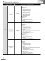
6.1 List of Alternative I/O Module Models
I/OLINK series model
Product
Model name
AJ55TB3-4D
(when positive common
type is used)
AJ55TB3-4D
(when negative common
type is used)
AnyWire DB A20 series alternative model
Model name
A20SB-04U
A20SB-04US
(1) External wiring: Changed
(2) Number of modules: Not changed
(3) Program: Changed
(4) Specifications:
Rated input voltage: Not changed
Rated input current: Not changed
ON voltage/ON current: Changed
OFF voltage/OFF current: Changed
Input resistance: Not changed
(5) Functions: Changed (wiring: 3-wire 2-wire) (A positive common type cannot
be used.)
A20SB-08UD
(1) External wiring: Changed
(2) Number of modules: Not changed
(3) Program: Changed
(4) Specifications:
Rated input voltage: Not changed
Rated input current: Not changed
ON voltage/ON current: Changed
OFF voltage/OFF current: Changed
Input resistance: Not changed
(5) Functions: Changed (A negative common type cannot be used.)
A20SB-08USD-1
(1) External wiring: Changed
(2) Number of modules: Not changed
(3) Program: Changed
(4) Specifications:
Rated input voltage: Not changed
Rated input current: Not changed
ON voltage/ON current: Changed
OFF voltage/OFF current: Changed
Input resistance: Not changed
(5) Functions: Changed (A positive common type cannot be used.)
Input module
AJ55TB3-8D
(when positive common
type is used)
AJ55TB3-8D
(when negative common
type is used)
6-1
Remarks (restrictions)
(1) External wiring: Changed
(2) Number of modules: Not changed
(3) Program: Changed
(4) Specifications:
Rated input voltage: Not changed
Rated input current: Not changed
ON voltage/ON current: Changed
OFF voltage/OFF current: Changed
Input resistance: Not changed
(5) Functions: Changed (wiring: 3-wire 2-wire) (A negative common type cannot
be used.)
6
REPLACING THE I/O MODULES
I/OLINK series model
Product
Model name
AJ55TB3-16D
(when positive common
type is used)
AnyWire DB A20 series alternative model
Model name
A20SB-16UD
A20SB-16USD
(1) External wiring: Changed
(2) Number of modules: Not changed
(3) Program: Changed
(4) Specifications:
Rated input voltage: Not changed
Rated input current: Not changed
ON voltage/ON current: Changed
OFF voltage/OFF current: Changed
Input resistance: Not changed
(5) Functions: Changed (A positive common type cannot be used.)(8 points/
common 16 points/common)
Input module
AJ55TB3-16D
(when negative common
type is used)
AJ55TB2-4R
AJ55TB2-8R
AJ55TB2-16R
A20PB-04RS
(1) External wiring: Changed
(2) Number of modules: Not changed
(3) Program: Changed
(4) Specifications:
Rated load voltage: Changed (The voltage that can be used is equivalent.)
Rated load current: Not changed
Maximum switching frequency: Changed (3600 times/hour 20 times/minute)
(5) Functions: Changed (4 points/common All points independent)
A20PB-08RS
(1) External wiring: Changed
(2) Number of modules: Not changed
(3) Program:
(4) Specifications:
Rated load voltage: Changed (The voltage that can be used is equivalent.)
Rated load current: Not changed
Maximum switching frequency: Changed (3600 times/hour 20 times/minute)
(5) Functions: Changed (8 points/common All points independent)
A20PB-16RS
(1) External wiring: Changed
(2) Number of modules: Not changed
(3) Program: Changed
(4) Specifications:
Rated load voltage: Changed (The voltage that can be used is equivalent.)
Rated load current: Not changed
Maximum switching frequency: Changed (3600 times/hour 20 times/minute)
(5) Functions: Changed (8 points/common All points independent)
Output module
AJ55TB2-4T
AJ55TB2-8T
AJ55TB2-16T
Remarks (restrictions)
(1) External wiring: Changed
(2) Number of modules: Not changed
(3) Program: Changed
(4) Specifications:
Rated input voltage: Not changed
Rated input current: Not changed
ON voltage/ON current: Changed
OFF voltage/OFF current: Changed
Input resistance: Not changed
(5) Functions: Changed (A negative common type cannot be used.)(8 points/
common 16 points/common)
A20PB-04U
(1) External wiring: Changed
(2) Number of modules: Not changed
(3) Program: Changed
(4) Specifications:
Rated load voltage: Changed (12VDC is not applicable.)
Rated load current: Changed (0.5A/point 0.2A/point)
(5) Functions: Changed (Surge suppressor: Supported Not supported)
A20PB-08U
(1) External wiring: Changed
(2) Number of modules: Not changed
(3) Program: Changed
(4) Specifications:
Rated load voltage: Changed (12VDC is not applicable.)
Rated load current: Changed (0.5A/point 0.2A/point)
(5) Functions: Changed (Surge suppressor: Supported Not supported)
A20PB-16U
(1) External wiring: Changed
(2) Number of modules: Not changed
(3) Program: Changed
(4) Specifications:
Rated load voltage: Changed (12VDC is not applicable.)
Rated load current: Changed (0.5A/point 0.2A/point)
(5) Functions: Changed (Surge suppressor: Supported Not supported)
6-2
6
REPLACING THE I/O MODULES
I/OLINK series model
Product
Model name
AJ55TB32-4DR
(when positive common
type is used)
I/O module
AJ55TB32-4DR
(when negative common
type is used)
AJ55TB32-8DR
(when positive common
type is used)
6-3
AnyWire DB A20 series alternative model
Model name
Remarks (restrictions)
A20SB-04U
+ A20PB-04RS
(1) External wiring: Changed
(2) Number of modules: Changed (Two modules are required.)
(3) Program: Changed
(4) Specifications:
(Input part)
Rated input voltage: Not changed
Rated input current: Not changed
ON voltage/ON current: Changed
OFF voltage/OFF current: Changed
Input resistance: Not changed
(Output part)
Rated load voltage: Changed (The voltage that can be used is equivalent.)
Rated load current: Not changed
Maximum switching frequency:
Changed (3600 times/hour 20 times/minute)
(5) Functions: Changed
(Input part)
Number of input points: 2 4
Wiring: 3-wire 2-wire
A negative common type cannot be used.
(Output part)
Number of output points: 2 4
2 points/common All points independent
A20SB-04US
+ A20PB-04RS
(1) External wiring: Changed
(2) Number of modules: Changed (Two modules are required.)
(3) Program: Changed
(4) Specifications:
(Input part)
Rated input voltage: Not changed
Rated input current: Not changed
ON voltage/ON current: Changed
OFF voltage/OFF current: Changed
Input resistance: Not changed
(Output part)
Rated load voltage: Changed (The voltage that can be used is equivalent.)
Rated load current: Not changed
Maximum switching frequency:
Changed (3600 times/hour 20 times/minute)
(5) Functions: Changed
(Input part)
Number of input points: 2 4
Wiring: 3-wire 2-wire
A positive common type cannot be used.
(Output part)
Number of output points: 2 4
2 points/common All points independent
A20SB-04U
+ A20PB-04RS
(1) External wiring: Changed
(2) Number of modules: Changed (Two modules are required.)
(3) Program: Changed
(4) Specifications:
(Input part)
Rated input voltage: Not changed
Rated input current: Not changed
ON voltage/ON current: Changed
OFF voltage/OFF current: Changed
Input resistance: Not changed
(Output part)
Rated load voltage: Changed (The voltage that can be used is equivalent.)
Rated load current: Not changed
Maximum switching frequency:
Changed (3600 times/hour 20 times/minute)
(5) Functions: Changed
(Input part)
Wiring: 3-wire 2-wire
A negative common type cannot be used.
(Output part)
4 points/common All points independent
6
REPLACING THE I/O MODULES
I/OLINK series model
Product
Model name
AJ55TB32-8DR
(when negative common
type is used)
I/O module
AJ55TB32-16DR
(when positive common
type is used)
AJ55TB32-16DR
(when negative common
type is used)
AnyWire DB A20 series alternative model
Model name
Remarks (restrictions)
A20SB-04US
+ A20PB-04RS
(1) External wiring: Changed
(2) Number of modules: Changed (Two modules are required.)
(3) Program: Changed
(4) Specifications:
(Input part)
Rated input voltage: Not changed
Rated input current: Not changed
ON voltage/ON current: Changed
OFF voltage/OFF current: Changed
Input resistance: Not changed
(Output part)
Rated load voltage: Changed (The voltage that can be used is equivalent.)
Rated load current: Not changed
Maximum switching frequency:
Changed (3600 times/hour 20 times/minute)
(5) Functions: Changed
(Input part)
Wiring: 3-wire 2-wire
A positive common type cannot be used.
(Output part)
4 points/common All points independent
A20SB-08UD
+ A20PB-08RS
(1) External wiring: Changed
(2) Number of modules: Changed (Two modules are required.)
(3) Program: Changed
(4) Specifications:
(Input part)
Rated input voltage: Not changed
Rated input current: Not changed
ON voltage/ON current: Changed
OFF voltage/OFF current: Changed
Input resistance: Not changed
(Output part)
Rated load voltage: Changed (The voltage that can be used is equivalent.)
Rated load current: Not changed
Maximum switching frequency:
Changed (3600 times/hour 20 times/minute)
(5) Functions: Changed
(Input part)
A negative common type cannot be used.
(Output part)
8 points/common All points independent
A20SB-08USD-1
+ A20PB-08RS
(1) External wiring: Changed
(2) Number of modules: Changed (Two modules are required.)
(3) Program: Changed
(4) Specifications:
(Input part)
Rated input voltage: Not changed
Rated input current: Not changed
ON voltage/ON current: Changed
OFF voltage/OFF current: Changed
Input resistance: Not changed
(Output part)
Rated load voltage: Changed (The voltage that can be used is equivalent.)
Rated load current: Not changed
Maximum switching frequency:
Changed (3600 times/hour 20 times/minute)
(5) Functions: Changed
(Input part)
A positive common type cannot be used.
(Output part)
8 points/common All points independent
6-4
6
REPLACING THE I/O MODULES
I/OLINK series model
Product
Model name
AJ55TB32-4DT
I/O module
AJ55TB32-8DT
AJ55TB32-16DT
6-5
AnyWire DB A20 series alternative model
Model name
Remarks (restrictions)
A20XB-16UD
(1) External wiring: Changed
(2) Number of modules: Not changed
(3) Program: Changed
(4) Specifications:
(Input part)
Rated input voltage: Not changed
Rated input current: Not changed
ON voltage/ON current: Changed
OFF voltage/OFF current: Changed
Input resistance: Not changed
(Output part)
Rated load voltage: Not changed
Rated load current: Changed (0.5A/point 0.2A/point)
(5) Functions: Changed
(Input part)
Number of input points: 2 8
(Output part)
Number of output points: 2 8
Surge suppressor: Supported Not supported
A20XB-16UD
(1) External wiring: Changed
(2) Number of modules: Not changed
(3) Program: Changed
(4) Specifications:
(Input part)
Rated input voltage: Not changed
Rated input current: Not changed
ON voltage/ON current: Changed
OFF voltage/OFF current: Changed
Input resistance: Not changed
(Output part)
Rated load voltage: Not changed
Rated load current: Changed (0.5A/point 0.2A/point)
(5) Functions: Changed
(Input part)
Number of input points: 4 8
(Output part)
Number of output points: 4 8
Surge suppressor: Supported Not supported
A20XB-16UD
(1) External wiring: Changed
(2) Number of modules: Not changed
(3) Program: Changed
(4) Specifications:
(Input part)
Rated input voltage: Not changed
Rated input current: Not changed
ON voltage/ON current: Changed
OFF voltage/OFF current: Changed
Input resistance: Not changed
(Output part)
Rated load voltage: Not changed
Rated load current: Changed (0.5A/point 0.2A/point)
(5) Functions: Changed
(Input part)
None
(Output part)
Surge suppressor: Supported Not supported
6
REPLACING THE I/O MODULES
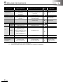
6.2 I/O Module Specifications Comparisons
6.2.1 Input module specifications comparisons
(1) Comparisons between AJ55TB3-4D and A20SB-04U
: Compatible,
Specifications
Number of input points
AJ55TB3-4D
A20SB-04U
4 points
4 points
Insulation method
External input ↔ Internal circuit:
External input ↔ Internal circuit: Not insulated
Photocoupler
Internal circuit ↔ Transmission circuit:
Internal circuit ↔ Transmission circuit:
Photocoupler
Not insulated
Input type
Positive/negative common shared type
Positive common type
24VDC
24VDC
Rated input voltage
Rated input current
Operating voltage range
Maximum simultaneous on
input point
ON voltage/ON current
OFF voltage/OFF current
Input resistance
Response
time
Approx. 7mA
Approx. 7mA
19.2 to 26.4VDC
(ripple ratio within 5%)
21.6 to 27.6VDC
(ripple voltage 0.5Vp-p or less)
100%
100%
14VDC or higher/3.5mA or higher
16VDC or higher/5.5mA or higher
6VDC or lower/1.7mA or lower
8VDC or lower/2mA or lower
Approx. 3.3k
Approx. 3.3k
OFF ON
10ms or less
1ms or less
ON OFF
10ms or less
1ms or less
4 points per common
(3-wire type terminal block)
4 points per common
(2-wire type terminal block)
Common terminal
arrangement
Operation indicator
External wiring method
Applicable wire size
ON indication (LED)
ON indication (LED)
16-point terminal block (M3 screw)
Transmission circuit included
10-point terminal block (M3 screw)
Transmission circuit included
0.75 to 2mm
2
: Partially changed, ×: Not compatible
Compat-
Precautions for
ibility
replacement
The insulated locations are
different.
A negative common type
cannot be used.*1
Operating voltage range is
different.
ON voltage and ON current
are increased.*2
OFF voltage and OFF current
are increased.*2
To connect an item such as a
3-wire type sensor, an
external common terminal
block is required.
Wiring must be changed.
Existing wires can be used but
applicable crimping terminals
are different.
For details, refer to Section
6.3.
0.3 to 1.25mm2
(when the following applicable crimping
terminals are used: 0.75 to 2mm2)
Applicable crimping
terminal
Voltage
I/O module
power
supply
Current
External dimensions
1.25-3, 1.25-YS3A,
2-S3, 2-YS3A
V1.25-3, V1.25-YS3A,
V2-S3, V2-YS3A
For wire sizes 0.75 to 2mm2
R2-3SL, RAV2-3SL, RAP2-3SL,
VD2-3S, VD2-3.5SS, VD2-3.5S,
VDAV2-3.5SS, VDAV2-3.5S
15.6 to 27.6VDC
21.6 to 27.6VDC
(ripple voltage 0.5Vp-p or less)
35mA
50mA
50(H) × 82(W) × 66(D) mm
40(H) × 65(W) × 60(D) mm
Screw mounted
Screw mounted
Mounted to DIN rail
Mounted to DIN rail
0.2kg
0.09kg
Installation method
Weight
*1
For the negative common type, use A20SB-04US.
*2
Check the specifications of the sensors or switches to be connected to the A20SB-04U.
Operating voltage range is
different.
Because the current
consumption has increased,
the current capacity must be
reviewed.
The shape is different.
×
Because mounting hole size is
different, reworking is
required.
The A20SB-04U can be
mounted to the existing DIN
rail.
6-6
6
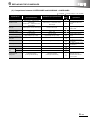
REPLACING THE I/O MODULES
(2) Comparisons between AJ55TB3-4D and A20SB-04US
: Compatible,
Specifications
Number of input points
AJ55TB3-4D
A20SB-04US
4 points
4 points
Insulation method
External input ↔ Internal circuit:
External input ↔ Internal circuit: Not insulated
Photocouplerd
Internal circuit ↔ Transmission circuit:
Internal circuit ↔ Transmission circuit:
Photocoupler
Not insulated
Input type
Positive/negative common shared type
24VDC
24VDC
Rated input current
Approx. 7mA
Approx. 7mA
19.2 to 26.4VDC
(ripple ratio within 5%)
21.6 to 27.6VDC
(ripple voltage 0.5Vp-p or less)
100%
100%
14VDC or higher/3.5mA or higher
16VDC or higher/5.5mA or higher
6VDC or lower/1.7mA or lower
8VDC or lower/2mA or lower
Maximum simultaneous on
input point
ON voltage/ON current
OFF voltage/OFF current
Input resistance
Response
time
Approx. 3.3k
Approx. 3.3k
OFF ON
10ms or less
1ms or less
ON OFF
10ms or less
1ms or less
4 points per common
(3-wire type terminal block)
4 points per common
(2-wire type terminal block)
Common terminal
arrangement
Operation indicator
External wiring method
Applicable wire size
ON indication (LED)
ON indication (LED)
16-point terminal block (M3 screw)
Transmission circuit included
10-point terminal block (M3 screw)
Transmission circuit included
0.75 to
2mm2
Precautions for
ibility
replacement
The insulated locations are
different.
A negative common type
Negative common type
Rated input voltage
Operating voltage range
: Partially changed, ×: Not compatible
Compat-
cannot be used.*1
Operating voltage range is
different.
ON voltage and ON current
are increased.*2
OFF voltage and OFF current
are increased.*2
To connect an item such as a
3-wire type sensor, an
external common terminal
block is required.
Wiring must be changed.
Existing wires can be used but
applicable crimping terminals
are different.
For details, refer to Section
6.3.
0.3 to 1.25mm2
(when the following applicable crimping
terminals are used: 0.75 to 2mm2)
Applicable crimping
terminal
Voltage
I/O module
power
supply
Current
External dimensions
1.25-3, 1.25-YS3A,
2-S3, 2-YS3A
V1.25-3, V1.25-YS3A,
V2-S3, V2-YS3A
For wire sizes 0.75 to 2mm2
R2-3SL, RAV2-3SL, RAP2-3SL,
VD2-3S, VD2-3.5SS, VD2-3.5S,
VDAV2-3.5SS, VDAV2-3.5S
15.6 to 27.6VDC
21.6 to 27.6VDC
(ripple voltage 0.5Vp-p or less)
35mA
43mA
50(H) × 82(W) × 66(D) mm
40(H) × 65(W) × 60(D) mm
Screw mounted
Screw mounted
Mounted to DIN rail
Mounted to DIN rail
0.2kg
0.09kg
Installation method
Weight
6-7
*1
For the positive common type, use A20SB-04U.
*2
Check the specifications of the sensors or switches to be connected to the A20SB-04US.
Operating voltage range is
different.
Because the current
consumption has increased,
the current capacity must be
reviewed.
The shape is different.
×
Because mounting hole size is
different, reworking is
required.
The A20SB-04US can be
mounted to the existing DIN
rail.
6
REPLACING THE I/O MODULES
(3) Comparisons between AJ55TB3-8D and A20SB-08UD
: Compatible,
Specifications
Number of input points
AJ55TB3-8D
A20SB-08UD
8 points
8 points
Insulation method
External input ↔ Internal circuit:
External input ↔ Internal circuit: Not insulated
Photocoupler
Internal circuit ↔ Transmission circuit:
Internal circuit ↔ Transmission circuit:
Photocoupler
Not insulated
Input type
Positive/negative common shared type
24VDC
24VDC
Rated input current
Approx. 7mA
Approx. 7mA
19.2 to 26.4VDC
(ripple ratio within 5%)
21.6 to 27.6VDC
(ripple voltage 0.5Vp-p or less)
100%
100%
14VDC or higher/3.5mA or higher
16VDC or higher/5.5mA or higher
6VDC or lower/1.7mA or lower
8VDC or lower/2mA or lower
Approx. 3.3k
Approx. 3.3k
Maximum simultaneous on
input point
ON voltage/ON current
OFF voltage/OFF current
Input resistance
Response
time
OFF ON
10ms or less
1ms or less
ON OFF
10ms or less
1ms or less
8 points per common
(3-wire type terminal block)
8 points per common
(3-wire type terminal block)
Common terminal
arrangement
Operation indicator
External wiring method
ON indication (LED)
ON indication (LED)
24-point terminal block (M3 screw)
Transmission circuit included
30-point terminal block (M3 screw)
Transmission circuit included
2
Precautions for
ibility
replacement
The insulated locations are
different.
A negative common type
Positive common type
Rated input voltage
Operating voltage range
: Partially changed, ×: Not compatible
Compat-
cannot be used.*1
Operating voltage range is
different.
ON voltage and ON current
are increased.*2
OFF voltage and OFF current
are increased.*2
Wiring must be changed.
Existing wires can be used but
applicable crimping terminals
are different.
For details, refer to Section
6.3.
0.3 to 1.25mm2
(when the following applicable crimping
Applicable wire size
0.75 to 2mm
Applicable crimping
terminal
1.25-3, 1.25-YS3A,
2-S3, 2-YS3A
V1.25-3, V1.25-YS3A,
V2-S3, V2-YS3A
For wire sizes 0.75 to 2mm2
R2-3SL, RAV2-3SL, RAP2-3SL,
VD2-3S, VD2-3.5SS, VD2-3.5S,
VDAV2-3.5SS, VDAV2-3.5S
15.6 to 27.6VDC
21.6 to 27.6VDC
(ripple voltage 0.5Vp-p or less)
terminals are used: 0.75 to 2mm2)
Voltage
I/O module
power
supply
Current
External dimensions
45mA
117mA
50(H) × 114(W) × 66(D) mm
40(H) × 140(W) × 60(D) mm
Screw mounted
Screw mounted
Mounted to DIN rail
Mounted to DIN rail
0.3kg
0.18kg
Installation method
Weight
*1
For the negative common type, use A20SB-08USD-1.
*2
Check the specifications of the sensors or switches to be connected to the A20SB-08UD.
Operating voltage range is
different.
Because the current
consumption has increased,
the current capacity must be
reviewed.
The shape is different.
×
Because mounting hole size is
different, reworking is
required.
The A20SB-08UD can be
mounted to the existing DIN
rail.
6-8
6
REPLACING THE I/O MODULES
(4) Comparisons between AJ55TB3-8D and A20SB-08USD-1
: Compatible,
Specifications
Number of input points
AJ55TB3-8D
A20SB-08USD-1
8 points
8 points
Insulation method
External input ↔ Internal circuit:
External input ↔ Internal circuit: Not insulated
Photocoupler
Internal circuit ↔ Transmission circuit:
Internal circuit ↔ Transmission circuit:
Photocoupler
Not insulated
Input type
Positive/negative common shared type
24VDC
24VDC
Rated input current
Approx. 7mA
Approx. 7mA
19.2 to 26.4VDC
(ripple ratio within 5%)
21.6 to 27.6VDC
(ripple voltage 0.5Vp-p or less)
100%
100%
14VDC or higher/3.5mA or higher
16VDC or higher/5.5mA or higher
6VDC or lower/1.7mA or lower
8VDC or lower/2mA or lower
Maximum simultaneous on
input point
ON voltage/ON current
OFF voltage/OFF current
Input resistance
Response
time
Approx. 3.3k
Approx. 3.3k
OFF ON
10ms or less
1ms or less
ON OFF
10ms or less
1ms or less
8 points per common
(3-wire type terminal block)
8 points per common
(3-wire type terminal block)
Common terminal
arrangement
Operation indicator
External wiring method
ON indication (LED)
ON indication (LED)
24-point terminal block (M3 screw)
Transmission circuit included
30-point terminal block (M3 screw)
Transmission circuit included
2
Precautions for
ibility
replacement
The insulated locations are
different.
A positive common type
Negative common type
Rated input voltage
Operating voltage range
: Partially changed, ×: Not compatible
Compat-
cannot be used.*1
Operating voltage range is
different.
ON voltage and ON current
are increased.*2
OFF voltage and OFF current
are increased.*2
Wiring must be changed.
Existing wires can be used but
applicable crimping terminals
are different.
For details, refer to Section
6.3.
0.3 to 1.25mm2
(when the following applicable crimping
Applicable wire size
0.75 to 2mm
Applicable crimping
terminal
1.25-3, 1.25-YS3A,
2-S3, 2-YS3A
V1.25-3, V1.25-YS3A,
V2-S3, V2-YS3A
For wire sizes 0.75 to 2mm2
R2-3SL, RAV2-3SL, RAP2-3SL,
VD2-3S, VD2-3.5SS, VD2-3.5S,
VDAV2-3.5SS, VDAV2-3.5S
15.6 to 27.6VDC
21.6 to 27.6VDC
(ripple voltage 0.5Vp-p or less)
terminals are used: 0.75 to 2mm2)
Voltage
I/O module
power
supply
Current
External dimensions
45mA
117mA
50(H) × 114(W) × 66(D) mm
40(H) × 140(W) × 60(D) mm
Screw mounted
Screw mounted
Mounted to DIN rail
Mounted to DIN rail
0.3kg
0.25kg
Operating voltage range is
different.
Because the current
consumption has increased,
the current capacity must be
reviewed.
The shape is different.
×
Installation method
Weight
6-9
*1
For the positive common type, use A20SB-08UD.
*2
Check the specifications of the sensors or switches to be connected to the A20SB-08USD-1.
Because mounting hole size is
different, reworking is
required.
The A20SB-08USD-1 can be
mounted to the existing DIN
rail.
6
REPLACING THE I/O MODULES
(5) Comparisons between AJ55TB3-16D and A20SB-16UD
: Compatible,
Specifications
Number of input points
AJ55TB3-16D
A20SB-16UD
16 points
16 points
Insulation method
External input ↔ Internal circuit:
External input ↔ Internal circuit: Not insulated
Photocoupler
Internal circuit ↔ Transmission circuit:
Internal circuit ↔ Transmission circuit:
Photocoupler
Not insulated
Input type
Positive/negative common shared type
24VDC
24VDC
Rated input current
Approx. 7mA
Approx. 7mA
19.2 to 26.4VDC
(ripple ratio within 5%)
21.6 to 27.6VDC
(ripple voltage 0.5Vp-p or less)
100%
100%
14VDC or higher/3.5mA or higher
16VDC or higher/5.5mA or higher
6VDC or lower/1.7mA or lower
8VDC or lower/2mA or lower
Approx. 3.3k
Approx. 3.3k
Maximum simultaneous on
input point
ON voltage/ON current
OFF voltage/OFF current
Input resistance
Response
time
OFF ON
10ms or less
1ms or less
ON OFF
10ms or less
1ms or less
8 points per common
(3-wire type terminal block)
16 points per common
(3-wire type terminal block)
Common terminal
arrangement
Operation indicator
External wiring method
Applicable wire size
ON indication (LED)
ON indication (LED)
40-point terminal block (M3 screw)
Transmission circuit included
40-point terminal block (M3 screw)
Transmission circuit included
0.75 to 2mm
2
Precautions for
ibility
replacement
The insulated locations are
different.
A negative common type
Positive common type
Rated input voltage
Operating voltage range
: Partially changed, ×: Not compatible
Compat-
cannot be used.*1
Operating voltage range is
different.
ON voltage and ON current
are increased.*2
OFF voltage and OFF current
are increased.*2
The A20SB-16UD changes
from 2 commons to 1
common.
Wiring must be changed.
Existing wires can be used but
applicable crimping terminals
are different.
For details, refer to Section
6.3.
0.3 to 1.25mm2
(when the following applicable crimping
terminals are used: 0.75 to 2mm2)
1.25-3, 1.25-YS3A,
2-S3, 2-YS3A
V1.25-3, V1.25-YS3A,
V2-S3, V2-YS3A
For wire sizes 0.75 to 2mm2
R2-3SL, RAV2-3SL, RAP2-3SL,
VD2-3S, VD2-3.5SS, VD2-3.5S,
VDAV2-3.5SS, VDAV2-3.5S
Voltage
15.6 to 27.6VDC
21.6 to 27.6VDC
(ripple voltage 0.5Vp-p or less)
Current
60mA
233mA
50(H) × 177(W) × 66(D) mm
40(H) × 190(W) × 60(D) mm
Screw mounted
Screw mounted
Mounted to DIN rail
Mounted to DIN rail
0.4kg
0.24kg
Applicable crimping
terminal
I/O module
power
supply
External dimensions
Installation method
Weight
*1
For the negative common type, use A20SB-16USD.
*2
Check the specifications of the sensors or switches to be connected to the A20SB-16UD.
Operating voltage range is
different.
Because the current
consumption has increased,
the current capacity must be
reviewed.
The shape is different.
×
Because mounting hole size is
different, reworking is
required.
The A20SB-16UD can be
mounted to the existing DIN
rail.
6 - 10
6
REPLACING THE I/O MODULES
(6) Comparisons between AJ55TB3-16D and A20SB-16USD
: Compatible,
Specifications
Number of input points
AJ55TB3-16D
A20SB-16USD
16 points
16 points
Insulation method
External input ↔ Internal circuit:
External input ↔ Internal circuit: Not insulated
Photocoupler
Internal circuit ↔ Transmission circuit:
Internal circuit ↔ Transmission circuit:
Photocoupler
Not insulated
Input type
Positive/negative common shared type
24VDC
24VDC
Rated input current
Approx. 7mA
Approx. 7mA
19.2 to 26.4VDC
(ripple ratio within 5%)
21.6 to 27.6VDC
(ripple voltage 0.5Vp-p or less)
100%
100%
14VDC or higher/3.5mA or higher
16VDC or higher/4.5mA or higher
6VDC or lower/1.7mA or lower
6VDC or lower/1mA or lower
Approx. 3.3k
Approx. 3.3k
OFF ON
10ms or less
1ms or less
ON OFF
10ms or less
1ms or less
8 points per common
(3-wire type terminal block)
16 points per common
(3-wire type terminal block)
Maximum simultaneous on
input point
ON voltage/ON current
OFF voltage/OFF current
Input resistance
Response
time
Common terminal
arrangement
Operation indicator
External wiring method
ON indication (LED)
ON indication (LED)
40-point terminal block (M3 screw)
Transmission circuit included
40-point terminal block (M3 screw)
Transmission circuit included
2
Precautions for
ibility
replacement
The insulated locations are
different.
A positive common type
Negative common type
Rated input voltage
Operating voltage range
: Partially changed, ×: Not compatible
Compat-
cannot be used.*1
Operating voltage range is
different.
ON voltage and ON current
are increased.*2
OFF current is decreased.*2
The A20SB-16USD changes
from 2 commons to 1
common.
Wiring must be changed.
Existing wires can be used but
applicable crimping terminals
are different.
For details, refer to Section
6.3.
0.3 to 1.25mm2
(when the following applicable crimping
Applicable wire size
0.75 to 2mm
Applicable crimping
terminal
1.25-3, 1.25-YS3A,
2-S3, 2-YS3A
V1.25-3, V1.25-YS3A,
V2-S3, V2-YS3A
For wire sizes 0.75 to 2mm2
R2-3SL, RAV2-3SL, RAP2-3SL,
VD2-3S, VD2-3.5SS, VD2-3.5S,
VDAV2-3.5SS, VDAV2-3.5S
15.6 to 27.6VDC
21.6 to 27.6VDC
(ripple voltage 0.5Vp-p or less)
terminals are used: 0.75 to 2mm2)
Voltage
I/O module
power
supply
Current
External dimensions
60mA
233mA
50(H) × 177(W) × 66(D) mm
40(H) × 190(W) × 60(D) mm
Screw mounted
Screw mounted
Mounted to DIN rail
Mounted to DIN rail
0.4kg
0.24kg
Operating voltage range is
different.
Because the current
consumption has increased,
the current capacity must be
reviewed.
The shape is different.
×
Installation method
Weight
6 - 11
*1
For the positive common type, use A20SB-16UD.
*2
Check the specifications of the sensors or switches to be connected to the A20SB-16USD.
Because mounting hole size is
different, reworking is
required.
The A20SB-16USD can be
mounted to the existing DIN
rail.
6
REPLACING THE I/O MODULES
6.2.2 Output module specifications
(1) Comparisons between AJ55TB2-4R and A20PB-04RS
: Compatible,
Specifications
Number of output points
Insulation method
Output type
AJ55TB2-4R
A20PB-04RS
4 points
4 points
External output ↔ Internal circuit:
Photocoupler
Internal circuit ↔ Transmission circuit:
Not insulated
External output ↔ Internal circuit: Relay
Internal circuit ↔ Transmission circuit:
Photocoupler
Contact output type
Contact output type
24VDC 2A (resistance load)/point
240VAC 2A (COS=1)/point
8A/common
30VDC 2A (resistance load)/point
220VAC 2A (COS=1)/point
1A (induced load)/point
5VDC 1mA
0.1VDC 0.1mA
(reference value)
250VAC 110VDC
250VAC 110VDC
OFF ON
10ms or less
10ms or less
ON OFF
12ms or less
10ms or less
Mechanical
20 million times or more
20 million times or more
Rated switching voltage/current load
100,000 times or more
200VAC 1.5A, 240VAC 1A
(COS=0.7) 100,000 times or more
200VAC 1A, 240VAC 0.5A
(COS=0.35) 100,000 times or more
24VDC 1A, 100VDC 0.1A
(L/R=7ms) 100,000 times or more
100,000 times or more
3,600 times/hour
20 times/minute
Surge suppressor
None
None
Common terminal
arrangement
4 points per common
(2-wire type terminal block)
All points independent
(2-wire type terminal block)
Rated load voltage/current
Minimum switching load
Maximum switching voltage
Response
time
Life
Electrical
Maximum switching
frequency
Operation indicator
External wiring method
ON indication (LED)
ON indication (LED)
16-point terminal block (M3 screw)
Transmission circuit included
20-point terminal block
Transmission circuit included
2
: Partially changed, ×: Not compatible
Compat-
Precautions for
ibility
replacement
The insulation method is
different.
The rated load voltage and
current are different.
Check the specifications of the
load to be used.
Maximum switching frequency
is different.
–
Because 4 points per common
is changed to all points
independent, the wiring is
different.
0.3 to 1.25mm2
(when the following applicable crimping
Wiring must be changed.
Existing wires can be used but
applicable crimping terminals
are different.
For details, refer to Section 6.3.
Applicable wire size
0.75 to 2mm
Applicable crimping
terminal
1.25-3, 1.25-YS3A,
2-S3, 2-YS3A
V1.25-3, V1.25-YS3A,
V2-S3, V2-YS3A
For wire sizes 0.75 to 2mm2
R2-3SL, RAV2-3SL, RAP2-3SL,
VD2-3S, VD2-3.5SS, VD2-3.5S,
VDAV2-3.5SS, VDAV2-3.5S
Voltage
24VDC ± 10%
Ripple voltage 4Vp-p or less
–
–
Current
23mA
(24VDC TYP. all points ON)
–
–
Voltage
15.6 to 27.6VDC
21.6 to 27.6VDC
(ripple voltage 0.5Vp-p or less)
Current
50mA
90mA
50(H) × 82(W) × 66(D) mm
40(H) × 100(W) × 60(D) mm
Screw mounted
Screw mounted
Mounted to DIN rail
Mounted to DIN rail
0.2kg
0.14kg
terminals are used: 0.75 to 2mm2)
External
power
supply
I/O module
power
supply
External dimensions
Installation method
Weight
The A20PB-04RS external
power supply and the I/O
module power supply are
shared.
Operating voltage range is
different.
Because the current
consumption has increased, the
current capacity must be
reviewed.
The shape is different.
×
Because mounting hole size is
different, reworking is required.
The A20PB-04RS can be
mounted to the existing DIN rail.
6 - 12
6
REPLACING THE I/O MODULES
(2) Comparisons between AJ55TB2-8R and A20PB-08RS
: Compatible,
Specifications
Number of output points
Insulation method
Output type
Rated load voltage/current
Minimum switching load
Maximum switching voltage
Response
time
AJ55TB2-8R
A20PB-08RS
8 points
8 points
External output ↔ Internal circuit:
Photocoupler
Internal circuit ↔ Transmission circuit:
Not insulated
External output ↔ Internal circuit: Relay
Internal circuit ↔ Transmission circuit:
Photocoupler
Contact output type
Contact output type
24VDC 2A (resistance load)/point
240VAC 2A (COS=1)/point
8A/common
30VDC 2A (resistance load)/point
220VAC 2A (COS=1)/point
1A (induced load)/point
5VDC 1mA
0.1VDC 0.1mA
(reference value)
250VAC 110VDC
250VAC 110VDC
OFF ON
10ms or less
10ms or less
ON OFF
12ms or less
10ms or less
Mechanical
20 million times or more
20 million times or more
Rated switching voltage/current load
100,000 times or more
200VAC 1.5A, 240VAC 1A
(COS=0.7) 100,000 times or more
200VAC 1A, 240VAC 0.5A
(COS=0.35) 100,000 times or more
24VDC 1A, 100VDC 0.1A
(L/R=7ms) 100,000 times or more
100,000 times or more
3,600 times/hour
20 times/minute
Surge suppressor
None
None
Common terminal
arrangement
8 points per common
(2-wire type terminal block)
All points independent
(2-wire type terminal block)
Life
Electrical
Maximum switching
frequency
Operation indicator
External wiring method
Applicable wire size
ON indication (LED)
ON indication (LED)
24-point terminal block (M3 screw)
Transmission circuit included
30-point terminal block (M3 screw)
Transmission circuit included
2
0.75 to 2mm
: Partially changed, ×: Not compatible
Compat-
Precautions for
ibility
replacement
The insulation method is
different.
The rated load voltage and
current are different.
Check the specifications of the
load to be used.
Maximum switching frequency
is different.
–
Because 8 points per common
is changed to all points
independent, the wiring is
different.
0.3 to 1.25mm2
(when the following applicable crimping
Wiring must be changed.
Existing wires can be used but
applicable crimping terminals
are different.
For details, refer to Section 6.3.
terminals are used: 0.75 to 2mm2)
1.25-3, 1.25-YS3A,
2-S3, 2-YS3A
V1.25-3, V1.25-YS3A,
V2-S3, V2-YS3A
For wire sizes 0.75 to 2mm2
R2-3SL, RAV2-3SL, RAP2-3SL,
VD2-3S, VD2-3.5SS, VD2-3.5S,
VDAV2-3.5SS, VDAV2-3.5S
Voltage
24VDC ± 10%
Ripple voltage 4Vp-p or less
–
–
Current
45mA
(24VDC TYP. all points ON)
–
–
Voltage
15.6 to 27.6VDC
21.6 to 27.6VDC
(ripple voltage 0.5Vp-p or less)
Applicable crimping
terminal
External
power
supply
I/O module
power
supply
Current
External dimensions
65mA
104mA
50(H) × 114(W) × 66(D) mm
40(H) × 140(W) × 60(D) mm
Screw mounted
Screw mounted
Mounted to DIN rail
Mounted to DIN rail
0.3kg
0.2kg
Installation method
Weight
6 - 13
The A20PB-08RS external
power supply and the I/O
module power supply are
shared.
Operating voltage range is
different.
Because the external power
supply and the I/O module
power supply are shared, the
consumed current is decreased.
The shape is different.
×
Because mounting hole size is
different, reworking is required.
The A20PB-08RS can be
mounted to the existing DIN rail.
6
REPLACING THE I/O MODULES
(3) Comparisons between AJ55TB2-16R and A20PB-16RS
: Compatible,
Specifications
Number of output points
Insulation method
Output type
Rated load voltage/current
Minimum switching load
Maximum switching voltage
AJ55TB2-16R
A20PB-16RS
16 points
16 points
External output ↔ Internal circuit:
Photocoupler
Internal circuit ↔ Transmission circuit:
Not insulated
External output ↔ Internal circuit: Relay
Internal circuit ↔ Transmission circuit:
Photocoupler
Contact output type
Contact output type
24VDC 2A (resistance load)/point
240VAC 2A (COS=1)/point
8A/common
30VDC 2A (resistance load)/point
220VAC 2A (COS=1)/point
1A (induced load)/point
5VDC 1mA
0.1VDC 0.1mA
(reference value)
250VAC 110VDC
250VAC 110VDC
10ms or less
10ms or less
ON OFF
12ms or less
10ms or less
Mechanical
20 million times or more
20 million times or more
Rated switching voltage/current load
100,000 times or more
200VAC 1.5A, 240VAC 1A
(COS=0.7) 100,000 times or more
200VAC 1A, 240VAC 0.5A
(COS=0.35) 100,000 times or more
24VDC 1A, 100VDC 0.1A
(L/R=7ms) 100,000 times or more
100,000 times or more
3,600 times/hour
20 times/minute
Surge suppressor
None
None
Common terminal
arrangement
8 points per common
(2-wire type terminal block)
All points independent
(2-wire type terminal block)
Life
Electrical
Maximum switching
frequency
Operation indicator
External wiring method
Applicable wire size
ON indication (LED)
40-point terminal block (M3 screw)
Transmission circuit included
Existing wires can be used but
applicable crimping terminals
are different.
For details, refer to Section 6.3.
2mm2)
For wire sizes 0.75 to 2mm2
R2-3SL, RAV2-3SL, RAP2-3SL,
VD2-3S, VD2-3.5SS, VD2-3.5S,
VDAV2-3.5SS, VDAV2-3.5S
Voltage
24VDC ± 10%
Ripple voltage 4Vp-p or less
–
–
Current
90mA
(24VDC TYP. all points ON)
–
–
Voltage
15.6 to 27.6VDC
21.6 to 27.6VDC
(ripple voltage 0.5Vp-p or less)
Current
External dimensions
85mA
165mA
50(H) × 177(W) × 66(D) mm
40(H) × 190(W) × 60(D) mm
Screw mounted
Screw mounted
Mounted to DIN rail
Mounted to DIN rail
0.4kg
0.28kg
Installation method
Weight
Because 8 points per common
is changed to all points
independent, the wiring is
different.
1.25-3, 1.25-YS3A,
2-S3, 2-YS3A
V1.25-3, V1.25-YS3A,
V2-S3, V2-YS3A
Applicable crimping
terminal
I/O module
power
supply
The rated load voltage and
current are different.
0.3 to 1.25mm2
(when the following applicable crimping
terminals are used: 0.75 to
External
power
supply
The insulation method is
different.
–
ON indication (LED)
0.75 to 2mm
replacement
Maximum switching frequency
is different.
40-point terminal block (M3 screw)
Transmission circuit included
2
Precautions for
ibility
Check the specifications of the
load to be used.
OFF ON
Response
time
: Partially changed, ×: Not compatible
Compat-
The A20PB-16RS external
power supply and the I/O
module power supply are
shared.
Operating voltage range is
different.
Because the external power
supply and the I/O module
power supply are shared, the
consumed current is decreased.
The shape is different.
×
Because mounting hole size is
different, reworking is required.
The A20PB-16RS can be
mounted to the existing DIN rail.
6 - 14
6
REPLACING THE I/O MODULES
(4) Comparisons between AJ55TB2-4T and A20PB-04U
: Compatible,
Specifications
Number of output points
AJ55TB2-4T
A20PB-04U
4 points
4 points
: Partially changed, ×: Not compatible
Compat-
Precautions for
ibility
replacement
External output ↔ Internal circuit:
External output ↔ Internal circuit: Not insulated
Photocoupler
Internal circuit ↔ Transmission circuit:
Internal circuit ↔ Transmission circuit:
Photocoupler
Not insulated
Insulation method
The insulated locations are
different.
Output type
Sink type
Sink type
Rated load voltage
12/24VDC
24VDC
12VDC cannot be used.*1
Operating load voltage
range
10.2 to 30VDC
(peak voltage 30VDC)
21.6 to 27.6VDC
(ripple voltage 0.5Vp-p or less)
Operating voltage range is
different.
Maximum load voltage
0.5A/point
2A/common
0.2A/point
0.8A/common
The maximum load current
per point has decreased.
Check the specifications of
the load to be used.
4A, 10ms or less
500mA or lower
Leakage current at OFF
0.1mA or lower
0.1mA or lower
Maximum voltage drop at
ON
0.9VDC or lower (TYP.) 0.5A
1.5VDC or lower (MAX.) 0.5A
1V or lower
OFFON
2ms or less
1ms or less
ON OFF
2ms or less (resistance load)
1ms or less
Surge suppressor
Zener diode
None
Common terminal
arrangement
4 points per common
(2-wire type terminal block)
4 points per common
(2-wire type terminal block)
Maximum inrush current
Response
time
Operation indicator
Inrush current has decreased.
Check the specifications of
the load to be used.
Check the specifications of
the load to be used.
×
ON indication (LED)
ON indication (LED)
16-point terminal block (M3 screw)
Transmission circuit included
10-point terminal block (M3 screw)
Transmission circuit included
Applicable wire size
0.75 to 2mm2
0.3 to 1.25mm2
(when the following applicable crimping
Applicable crimping
terminal
1.25-3, 1.25-YS3A,
2-S3, 2-YS3A
V1.25-3, V1.25-YS3A,
V2-S3, V2-YS3A
For wire sizes 0.75 to 2mm2
R2-3SL, RAV2-3SL, RAP2-3SL,
VD2-3S, VD2-3.5SS, VD2-3.5S,
VDAV2-3.5SS, VDAV2-3.5S
Voltage
10.2 to 30VDC
–
–
Current
30mA
(24VDC TYP. per 1 common)
–
–
Voltage
15.6 to 27.6VDC
21.6 to 27.6VDC
(ripple voltage 0.5Vp-p or less)
External wiring method
Wiring must be changed.
Existing wires can be used but
applicable crimping terminals
are different.
For details, refer to Section
6.3.
terminals are used: 0.75 to 2mm2)
External
power
supply
I/O module
power
supply
Current
External dimensions
45mA
13mA
50(H) × 82(W) × 66(D) mm
40(H) × 65(W) × 60(D) mm
Screw mounted
Screw mounted
Mounted to DIN rail
Mounted to DIN rail
0.2kg
0.09g
Installation method
Weight
*1
6 - 15
When used on 12VDC, consider the use of an external relay.
The surge suppressor is not
built-in.
The A20PB-04U external
power supply and the I/O
module power supply are
shared.
Operating voltage range is
different.
Because the external power
supply and the I/O module
power supply are shared, the
consumed current is
decreased.
The shape is different.
×
Because mounting hole size is
different, reworking is
required.
The A20PB-04U can be
mounted to the existing DIN
rail.
6
REPLACING THE I/O MODULES
(5) Comparisons between AJ55TB2-8T and A20PB-08U
: Compatible,
Specifications
Number of output points
AJ55TB2-8T
A20PB-08U
8 points
8 points
: Partially changed, ×: Not compatible
Compat-
Precautions for
ibility
replacement
External output ↔ Internal circuit:
External output ↔ Internal circuit: Not insulated
Photocoupler
Internal circuit ↔ Transmission circuit:
Internal circuit ↔ Transmission circuit:
Photocoupler
Not insulated
Insulation method
The insulated locations are
different.
Output type
Sink type
Sink type
Rated load voltage
12/24VDC
24VDC
12VDC cannot be used.*1
Operating load voltage
range
10.2 to 30VDC
(peak voltage 30VDC)
21.6 to 27.6VDC
(ripple voltage 0.5Vp-p or less)
Operating voltage range is
different.
Maximum load voltage
0.5A/point
4A/common
0.2A/point
1.6A/common
The maximum load current
per point has decreased.
Check the specifications of
the load to be used.
4A, 10ms or less
500mA or lower
Maximum inrush current
Leakage current at OFF
0.1mA or lower
0.1mA or lower
0.9VDC or lower (TYP.) 0.5A
1.5VDC or lower (MAX.) 0.5A
1V or lower
OFF ON
2ms or less
1ms or less
ON OFF
2ms or less (resistance load)
1ms or less
Surge suppressor
Zener diode
None
Common terminal
arrangement
8 points per common
(2-wire type terminal block)
8 points per common
(2-wire type terminal block)
Maximum voltage drop at
ON
Response
time
Operation indicator
External wiring method
ON indication (LED)
ON indication (LED)
24-point terminal block (M3 screw)
Transmission circuit included
20-point terminal block (M3 screw)
Transmission circuit included
2
Inrush current has decreased.
Check the specifications of
the load to be used.
Check the specifications of
the load to be used.
×
Wiring must be changed.
Existing wires can be used but
applicable crimping terminals
are different.
For details, refer to Section
6.3.
0.3 to 1.25mm2
(when the following applicable crimping
Applicable wire size
0.75 to 2mm
Applicable crimping
terminal
1.25-3, 1.25-YS3A,
2-S3, 2-YS3A
V1.25-3, V1.25-YS3A,
V2-S3, V2-YS3A
For wire sizes 0.75 to 2mm2
R2-3SL, RAV2-3SL, RAP2-3SL,
VD2-3S, VD2-3.5SS, VD2-3.5S,
VDAV2-3.5SS, VDAV2-3.5S
Voltage
10.2 to 30VDC
–
–
Current
30mA
(24VDC TYP. per 1 common)
–
–
Voltage
15.6 to 27.6VDC
(peak voltage 27.6VDC)
21.6 to 27.6VDC
(ripple voltage 0.5Vp-p or less)
terminals are used: 0.75 to 2mm2)
External
power
supply
I/O module
power
supply
Current
External dimensions
55mA
21mA
50(H) × 114(W) × 66(D) mm
40(H) × 100(W) × 60(D) mm
Screw mounted
Screw mounted
Mounted to DIN rail
Mounted to DIN rail
0.3kg
0.13g
Installation method
Weight
*1
The surge suppressor is not
built-in.
External power supply for the
A20PB-08U is unnecessary.
Operating voltage range is
different.
Because the external power
supply and the I/O module
power supply are shared, the
consumed current is
decreased.
The shape is different.
×
Because mounting hole size is
different, reworking is
required.
The A20PB-08U can be
mounted to the existing DIN
rail.
When used on 12VDC, consider the use of an external relay.
6 - 16
6
REPLACING THE I/O MODULES
(6) Comparisons between AJ55TB2-16T and A20PB-16U
: Compatible,
Specifications
Number of output points
AJ55TB2-16T
A20PB-16U
16 points
16 points
: Partially changed, ×: Not compatible
Compat-
Precautions for
ibility
replacement
External output ↔ Internal circuit:
External output ↔ Internal circuit: Not insulated
Photocoupler
Internal circuit ↔ Transmission circuit:
Internal circuit ↔ Transmission circuit:
Photocoupler
Not insulated
Insulation method
The insulated locations are
different.
Output type
Sink type
Sink type
Rated load voltage
12/24VDC
24VDC
12VDC cannot be used.*1
Operating load voltage
range
10.2 to 30VDC
(peak voltage 30VDC)
21.6 to 27.6VDC
(ripple voltage 0.5Vp-p or less)
Operating voltage range is
different.
Maximum load voltage
0.5A/point
5A/common
0.2A/point
3.2A/common
The maximum load current
per point has decreased.
Check the specifications of
the load to be used.
4.0A, 10ms or less
500mA or lower
Leakage current at OFF
0.1mA or lower
0.1mA or lower
Maximum voltage drop at
ON
0.9VDC or lower (TYP.) 0.5A
1.5VDC or lower (MAX.) 0.5A
1V or lower
OFF ON
2ms or less
1ms or less
ON OFF
2ms or less (resistance load)
1ms or less
Surge suppressor
Zener diode
None
Common terminal
arrangement
16 points per common
(2-wire type terminal block)
16 points per common
(2-wire type terminal block)
Maximum inrush current
Response
time
Operation indicator
External wiring method
ON indication (LED)
ON indication (LED)
40-point terminal block (M3 screw)
Transmission circuit included
30-point terminal block (M3 screw)
Transmission circuit included
2
Inrush current has decreased.
Check the specifications of
the load to be used.
Check the specifications of
the load to be used.
×
Wiring must be changed.
Existing wires can be used but
applicable crimping terminals
are different.
For details, refer to Section
6.3.
0.3 to 1.25mm2
(when the following applicable crimping
Applicable wire size
0.75 to 2mm
Applicable crimping
terminal
1.25-3, 1.25-YS3A,
2-S3, 2-YS3A
V1.25-3, V1.25-YS3A,
V2-S3, V2-YS3A
For wire sizes 0.75 to 2mm2
R2-3SL, RAV2-3SL, RAP2-3SL,
VD2-3S, VD2-3.5SS, VD2-3.5S,
VDAV2-3.5SS, VDAV2-3.5S
Voltage
10.2 to 30VDC
–
–
Current
120mA
(24VDC TYP. per 1 common)
–
–
Voltage
15.6 to 27.6VDC
(peak voltage 27.6VDC)
21.6 to 27.6VDC
(ripple voltage 0.5Vp-p or less)
terminals are used: 0.75 to 2mm2)
External
power
supply
I/O module
power
supply
Current
External dimensions
70mA
33mA
50(H) × 177(W) × 66(D) mm
40(H) × 140(W) × 60(D) mm
Screw mounted
Screw mounted
Mounted to DIN rail
Mounted to DIN rail
0.4kg
0.18g
Installation method
Weight
*1
6 - 17
When used on 12VDC, consider the use of an external relay.
The surge suppressor is not
built-in.
The A20PB-16U external
power supply and the I/O
module power supply are
shared.
Operating voltage range is
different.
Because the external power
supply and the I/O module
power supply are shared, the
consumed current is
decreased.
The shape is different.
×
Because mounting hole size is
different, reworking is
required.
The A20PB-16U can be
mounted to the existing DIN
rail.
6
REPLACING THE I/O MODULES
6.2.3 I/O module specifications comparisons
(1) Comparisons between AJ55TB32-4DR and A20SB-04U + A20PB-04RS
: Compatible,
Specifications
Number of input points
AJ55TB32-4DR
input specifications
2 points
A20SB-04U input specifications
Insulation method
Input type
Positive/negative common shared type
Positive common type
24VDC
24VDC
Rated input current
Operating voltage range
Maximum simultaneous on
input point
ON voltage/ON current
OFF voltage/OFF current
Input resistance
Response
time
Approx. 7mA
Approx. 7mA
21.6 to 26.4VDC
(ripple voltage 4Vp-p or less)
21.6 to 27.6VDC
(ripple voltage 0.5Vp-p or less)
100%
100%
14VDC or higher/3.5mA or higher
16VDC or higher/5.5mA or higher
6VDC or lower/1.7mA or lower
8VDC or lower/2mA or lower
Approx. 3.3k
Approx. 3.3k
OFF ON
10ms or less
1ms or less
ON OFF
10ms or less
1ms or less
2 points per common
(3-wire type terminal block)
4 points per common
(2-wire type terminal block)
Common terminal
arrangement
Compat-
Precautions for
ibility
replacement
4 points
External input ↔ Internal circuit:
External input ↔ Internal circuit: Not insulated
Photocoupler
Internal circuit ↔ Transmission circuit:
Internal circuit ↔ Transmission circuit:
Photocoupler
Not insulated
Rated input voltage
: Partially changed, ×: Not compatible
The insulated locations are
different.
A negative common type
cannot be used.*1
Operating voltage range is
different.
ON voltage and ON current
are increased.*2
OFF voltage and OFF current
are increased.*2
To connect an item such as a
3-wire type sensor, an
external common terminal
block is required.
6 - 18
6
REPLACING THE I/O MODULES
Specifications
Number of output points
Insulation method
Output type
Rated load voltage/current
Minimum switching load
Maximum switching voltage
Response
time
OFF ON
AJ55TB32-4DR
output specifications
A20PB-04RS output specifications
2 points
4 points
External output ↔ Internal circuit:
Photocoupler
Internal circuit ↔ Transmission circuit:
Not insulated
External output ↔ Internal circuit: Relay
Internal circuit ↔ Transmission circuit:
Photocoupler
Contact output type
The rated load voltage and
current are different.
5VDC 1mA
0.1VDC 0.1mA
(reference value)
Check the specifications of
the load to be used.
250VAC 110VDC
250VAC 110VDC
10ms or less
10ms or less
12ms or less
10ms or less
20 million times or more
Rated switching voltage/current load
100,000 times or more
200VAC 1.5A, 240VAC 1A
(COS=0.7) 100,000 times or more
200VAC 1A, 240VAC 0.5A
(COS=0.35) 100,000 times or more
24VDC 1A, 100VDC 0.1A
(L/R=7ms) 100,000 times or more
100,000 times or more
3,600 times/hour
20 times/minute
Surge suppressor
None
None
Common terminal
arrangement
2 points per common
(2-wire type terminal block)
All points independent
(2-wire type terminal block)
6 - 19
The insulation method is
different.
30VDC 2A (resistance load)/point
220VAC 2A (COS=1)/point
1A (induced load)/point
20 million times or more
Maximum switching
frequency
replacement
Contact output type
Mechanical
Electrical
Precautions for
ibility
24VDC 2A (resistance load)/point
240VAC 2A (COS=1)/point
4A/common
ON OFF
Life
Compat-
*1
For the negative common type, use the A20SB-04US.
*2
Check the specifications of the sensors or switches to be connected to the A20SB-04U.
Maximum switching frequency
is different.
–
Because 2 points per common
is changed to all points
independent, the wiring is
different.
6
REPLACING THE I/O MODULES
: Compatible,
Specifications
Operation indicator
External wiring method
Applicable wire size
AJ55TB32-4DR
A20SB-04U
ON indication (LED)
16-point terminal block
(M3 screw)
Transmission circuit included
0.75 to 2mm2
A20PB-04RS
: Partially changed, ×: Not compatible
Compat-
Precautions for
ibility
replacement
ON indication (LED)
10-point terminal
block
(M3 screw)
Transmission circuit
included
20-point terminal
block
(M3 screw)
Transmission circuit
included
Wiring must be changed.
Existing wires can be used but
applicable crimping terminals
are different.
For details, refer to Section
6.3.
0.3 to 1.25mm2
(when the following applicable crimping
terminals are used: 0.75 to 2mm2)
Applicable crimping
terminal
External
power
supply
I/O module
power
supply
1.25-3, 1.25-YS3A,
2-S3, 2-YS3A
V1.25-3, V1.25-YS3A,
V2-S3, V2-YS3A
For wire sizes 0.75 to 2mm2
R2-3SL, RAV2-3SL, RAP2-3SL,
VD2-3S, VD2-3.5SS, VD2-3.5S,
VDAV2-3.5SS, VDAV2-3.5S
Voltage
24VDC ± 10%
Ripple voltage 4Vp-p or less
–
–
–
Current
12mA
(24VDC TYP. all points ON)
–
–
–
Voltage
15.6 to 27.6VDC
Current
External dimensions
21.6 to 27.6VDC
(ripple voltage 0.5Vp-p or less)
Operating voltage range is
different.
40mA
50mA
90mA
Because the current
consumption has increased,
the current capacity must be
reviewed.
50(H) × 82(W) × 66(D) mm
40(H) × 65(W)
× 60(D) mm
40(H) × 100(W)
× 60(D) mm
Screw mounted
Screw mounted
Installation method
Mounted to DIN rail
Weight
External power supply for the
A20SB-04U is unnecessary.
The A20PB-04RS external
power supply and the I/O
module power supply are
shared.
0.2kg
Mounted to DIN rail
0.09kg
0.14kg
×
The shape is different.
A mounting space for two
modules is required.
×
Because mounting hole size is
different, reworking is
required.
The A20SB-04U and A20PB04RS can be mounted to the
existing DIN rail.
Be careful about the mounting
dimensions as two modules
are required.
The weight is increased.
6 - 20
6
REPLACING THE I/O MODULES
(2) Comparisons between AJ55TB32-4DR and A20SB-04US + A20PB-04RS
: Compatible,
Specifications
Number of input points
AJ55TB32-4DR
input specifications
2 points
A20SB-04US input specifications
Insulation method
Input type
Positive/negative common shared type
Negative common type
Rated input voltage
24VDC
24VDC
Rated input current
Approx. 7mA
Approx. 7mA
21.6 to 26.4VDC
(ripple voltage 4Vp-p or less)
21.6 to 27.6VDC
(ripple voltage 0.5Vp-p or less)
100%
100%
14VDC or higher/3.5mA or higher
16VDC or higher/4.5mA or higher
6VDC or lower/1.7mA or lower
6VDC or lower/1mA or lower
Approx. 3.3k
Approx. 3.3k
OFF ON
10ms or less
1ms or less
ON OFF
10ms or less
1ms or less
2 points per common
(3-wire type terminal block)
4 points per common
(2-wire type terminal block)
Maximum simultaneous on
input point
ON voltage/ON current
OFF voltage/OFF current
Input resistance
Response
time
Common terminal
arrangement
6 - 21
Precautions for
ibility
replacement
4 points
External input ↔ Internal circuit:
External input ↔ Internal circuit: Not insulated
Photocoupler
Internal circuit ↔ Transmission circuit:
Internal circuit ↔ Transmission circuit:
Photocoupler
Not insulated
Operating voltage range
: Partially changed, ×: Not compatible
Compat-
The insulated locations are
different.
A positive common type
cannot be used.*1
Operating voltage range is
different.
ON voltage and ON current
are increased.*2
OFF current is decreased.*2
To connect an item such as a
3-wire type sensor, an
external common terminal
block is required.
6
REPLACING THE I/O MODULES
Specifications
Number of output points
Insulation method
Output type
Rated load voltage/current
Minimum switching load
Maximum switching voltage
Response
time
OFF ON
AJ55TB32-4DR
output specifications
A20PB-04RS output specifications
2 points
4 points
External output ↔ Internal circuit:
Photocoupler
Internal circuit ↔ Transmission circuit:
Not insulated
External output ↔ Internal circuit: Relay
Internal circuit ↔ Transmission circuit:
Photocoupler
The insulation method is
different.
Contact output type
30VDC 2A (resistance load)/point
220VAC 2A (COS=1)/point
1A (induced load)/point
The rated load voltage and
current are different.
5VDC 1mA
0.1VDC 0.1mA
(reference value)
Check the specifications of
the load to be used.
250VAC 110VDC
250VAC 110VDC
10ms or less
10ms or less
12ms or less
10ms or less
20 million times or more
20 million times or more
Rated switching voltage/current load
100,000 times or more
200VAC 1.5A, 240VAC 1A
(COS=0.7) 100,000 times or more
200VAC 1A, 240VAC 0.5A
(COS=0.35) 100,000 times or more
24VDC 1A, 100VDC 0.1A
(L/R=7ms) 100,000 times or more
100,000 times or more
3,600 times/hour
20 times/minute
Surge suppressor
None
None
Common terminal
arrangement
2 points per common
(2-wire type terminal block)
All points independent
(2-wire type terminal block)
Maximum switching
frequency
replacement
Contact output type
Mechanical
Electrical
Precautions for
ibility
24VDC 2A (resistance load)/point
240VAC 2A (COS=1)/point
4A/common
ON OFF
Life
Compat-
*1
For the positive common type, use the A20SB-04U.
*2
Check the specifications of the sensors or switches to be connected to the A20SB-04US.
Maximum switching frequency
is different.
–
Because 2 points per common
is changed to all points
independent, the wiring is
different.
6 - 22
6
REPLACING THE I/O MODULES
: Compatible,
Specifications
Operation indicator
External wiring method
Applicable wire size
AJ55TB32-4DR
A20SB-04US
ON indication (LED)
16-point terminal block
(M3 screw)
Transmission circuit included
0.75 to 2mm2
A20PB-04RS
: Partially changed, ×: Not compatible
Compat-
Precautions for
ibility
replacement
ON indication (LED)
10-point terminal
block
(M3 screw)
Transmission circuit
included
20-point terminal
block
(M3 screw)
Transmission circuit
included
Wiring must be changed.
Existing wires can be used but
applicable crimping terminals
are different.
For details, refer to Section
6.3.
0.3 to 1.25mm2
(when the following applicable crimping
terminals are used: 0.75 to 2mm2)
Applicable crimping
terminal
External
power
supply
I/O module
power
supply
1.25-3, 1.25-YS3A,
2-S3, 2-YS3A
V1.25-3, V1.25-YS3A,
V2-S3, V2-YS3A
For wire sizes 0.75 to 2mm2
R2-3SL, RAV2-3SL, RAP2-3SL,
VD2-3S, VD2-3.5SS, VD2-3.5S,
VDAV2-3.5SS, VDAV2-3.5S
Voltage
24VDC ± 10%
Ripple voltage 4Vp-p or less
–
–
–
Current
12mA
(24VDC TYP. all points ON)
–
–
–
Voltage
15.6 to 27.6VDC
(peak voltage 27.6VDC)
Current
External dimensions
21.6 to 27.6VDC
(ripple voltage 0.5Vp-p or less)
Operating voltage range is
different.
40mA
43mA
90mA
Because the current
consumption has increased,
the current capacity must be
reviewed.
50(H) × 82(W) × 66(D) mm
40(H) × 65(W)
× 60(D) mm
40(H) × 100(W)
× 60(D) mm
Screw mounted
Screw mounted
Installation method
Mounted to DIN rail
Weight
6 - 23
External power supply for the
A20SB-04US is unnecessary.
The A20PB-04RS external
power supply and the I/O
module power supply are
shared.
0.2kg
Mounted to DIN rail
0.09kg
0.14kg
×
The shape is different.
A mounting space for two
modules is required.
×
Because mounting hole size is
different, reworking is
required.
The A20SB-04US and
A20PB-04RS can be mounted
to the existing DIN rail.
Be careful about the mounting
dimensions as two modules
are required.
The weight is increased.
6
REPLACING THE I/O MODULES
(3) Comparisons between AJ55TB32-8DR and A20SB-04U + A20PB-04RS
: Compatible,
Specifications
Number of input points
AJ55TB32-8DR
input specifications
4 points
A20SB-04U input specifications
Insulation method
Input type
Positive/negative common shared type
Positive common type
Rated input voltage
24VDC
24VDC
Rated input current
Approx. 7mA
Approx. 7mA
21.6 to 26.4VDC
(ripple voltage 4Vp-p or less)
21.6 to 27.6VDC
(ripple voltage 0.5Vp-p or less)
100%
100%
14VDC or higher/3.5mA or higher
16VDC or higher/5.5mA or higher
6VDC or lower/1.7mA or lower
8VDC or lower/2mA or lower
Approx. 3.3k
Approx. 3.3k
Maximum simultaneous on
input point
ON voltage/ON current
OFF voltage/OFF current
Input resistance
Response
time
OFF ON
10ms or less
1ms or less
ON OFF
10ms or less
1ms or less
4 points per common
(3-wire type terminal block)
4 points per common
(2-wire type terminal block)
Common terminal
arrangement
Precautions for
ibility
replacement
4 points
External input ↔ Internal circuit:
External input ↔ Internal circuit: Not insulated
Photocoupler
Internal circuit ↔ Transmission circuit:
Internal circuit ↔ Transmission circuit:
Photocoupler
Not insulated
Operating voltage range
: Partially changed, ×: Not compatible
Compat-
The insulated locations are
different.
A negative common type
cannot be used.*1
Operating voltage range is
different.
ON voltage and ON current
are increased.*2
OFF voltage and OFF current
are increased.*2
To connect an item such as a
3-wire type sensor, an
external common terminal
block is required.
6 - 24
6
REPLACING THE I/O MODULES
Specifications
Number of output points
Insulation method
Output type
Rated load voltage/current
Minimum switching load
Maximum switching voltage
Response
time
OFF ON
AJ55TB32-8DR
output specifications
A20PB-04RS output specifications
4 points
4 points
External output ↔ Internal circuit:
Photocoupler
Internal circuit ↔ Transmission circuit:
Not insulated
External output ↔ Internal circuit: Relay
Internal circuit ↔ Transmission circuit:
Photocoupler
Contact output type
The rated load voltage and
current are different.
5VDC 1mA
0.1VDC 0.1mA
(reference value)
Check the specifications of
the load to be used.
250VAC 110VDC
250VAC 110VDC
10ms or less
10ms or less
12ms or less
10ms or less
20 million times or more
Rated switching voltage/current load
100,000 times or more
200VAC 1.5A, 240VAC 1A
(COS=0.7) 100,000 times or more
200VAC 1A, 240VAC 0.5A
(COS=0.35) 100,000 times or more
24VDC 1A, 100VDC 0.1A
(L/R=7ms) 100,000 times or more
100,000 times or more
3,600 times/hour
20 times/minute
Surge suppressor
None
None
Common terminal
arrangement
4 points per common
(2-wire type terminal block)
All points independent
(2-wire type terminal block)
6 - 25
The insulation method is
different.
30VDC 2A (resistance load)/point
220VAC 2A (COS=1)/point
1A (induced load)/point
20 million times or more
Maximum switching
frequency
replacement
Contact output type
Mechanical
Electrical
Precautions for
ibility
24VDC 2A (resistance load)/point
240VAC 2A (COS=1)/point
8A/common
ON OFF
Life
Compat-
*1
For the negative common type, use the A20SB-04US.
*2
Check the specifications of the sensors or switches to be connected to the A20SB-04U.
Maximum switching frequency
is different.
–
Because 4 points per common
is changed to all points
independent, the wiring is
different.
6
REPLACING THE I/O MODULES
: Compatible,
Specifications
Operation indicator
External wiring method
Applicable wire size
AJ55TB32-8DR
A20SB-04U
ON indication (LED)
24-point terminal block
(M3 screw)
Transmission circuit included
0.75 to 2mm2
A20PB-04RS
: Partially changed, ×: Not compatible
Compat- Precautions for replaceibility
10-point terminal
block
(M3 screw)
Transmission circuit
included
20-point terminal
block
(M3 screw)
Transmission circuit
included
Wiring must be changed.
Existing wires can be used but
applicable crimping terminals
are different.
For details, refer to Section
6.3.
0.3 to 1.25mm2
(when the following applicable crimping
terminals are used: 0.75 to 2mm2)
Applicable crimping
terminal
External
power
supply
I/O module
power
supply
1.25-3, 1.25-YS3A,
2-S3, 2-YS3A
V1.25-3, V1.25-YS3A,
V2-S3, V2-YS3A
For wire sizes 0.75 to 2mm2
R2-3SL, RAV2-3SL, RAP2-3SL,
VD2-3S, VD2-3.5SS, VD2-3.5S,
VDAV2-3.5SS, VDAV2-3.5S
Voltage
24VDC ± 10%
Ripple voltage 4Vp-p or less
–
–
–
Current
23mA
(24VDC TYP. all points ON)
–
–
–
Voltage
15.6 to 27.6VDC
Current
External dimensions
External power supply for the
A20SB-04U is unnecessary.
The A20PB-04RS external
power supply and the I/O
module power supply are
shared.
21.6 to 27.6VDC
(ripple voltage 0.5Vp-p or less)
Operating voltage range is
different.
50mA
50mA
90mA
Because the current
consumption has increased,
the current capacity must be
reviewed.
50(H) × 114(W) × 66(D) mm
40(H) × 65(W)
× 60(D) mm
40(H) × 100(W)
× 60(D) mm
Screw mounted
Screw mounted
Installation method
Mounted to DIN rail
Weight
ment
ON indication (LED)
0.3kg
Mounted to DIN rail
0.09kg
×
The shape is different.
A mounting space for two
modules is required.
×
Because mounting hole size is
different, reworking is
required.
The A20SB-04U and A20PB04RS can be mounted to the
existing DIN rail.
Be careful about the mounting
dimensions as two modules
are required.
0.14kg
6 - 26
6
REPLACING THE I/O MODULES
(4) Comparisons between AJ55TB32-8DR and A20SB-04US + A20PB-04RS
: Compatible,
Specifications
Number of input points
AJ55TB32-8DR
input specifications
4 points
A20SB-04US input specifications
Insulation method
Input type
Positive/negative common shared type
Negative common type
Rated input voltage
24VDC
24VDC
Rated input current
Approx. 7mA
Approx. 7mA
21.6 to 26.4VDC
(ripple voltage 4Vp-p or less)
21.6 to 27.6VDC
(ripple voltage 0.5Vp-p or less)
100%
100%
14VDC or higher/3.5mA or higher
16VDC or higher/4.5mA or higher
6VDC or lower/1.7mA or lower
6VDC or lower/1mA or lower
Approx. 3.3k
Approx. 3.3k
OFF ON
10ms or less
1ms or less
ON OFF
10ms or less
1ms or less
4 points per common
(3-wire type terminal block)
4 points per common
(2-wire type terminal block)
Maximum simultaneous on
input point
ON voltage/ON current
OFF voltage/OFF current
Input resistance
Response
time
Common terminal
arrangement
6 - 27
Precautions for
ibility
replacement
4 points
External input ↔ Internal circuit:
External input ↔ Internal circuit: Not insulated
Photocoupler
Internal circuit ↔ Transmission circuit:
Internal circuit ↔ Transmission circuit:
Photocoupler
Not insulated
Operating voltage range
: Partially changed, ×: Not compatible
Compat-
The insulated locations are
different.
A positive common type
cannot be used.*1
Operating voltage range is
different.
ON voltage and ON current
are increased.*2
OFF current is decreased.*2
To connect an item such as a
3-wire type sensor, an
external common terminal
block is required.
6
REPLACING THE I/O MODULES
Specifications
Number of output points
Insulation method
Output type
Rated load voltage/current
Minimum switching load
Maximum switching voltage
Response
time
OFF ON
AJ55TB32-8DR
output specifications
A20PB-04RS output specifications
4 points
4 points
External output ↔ Internal circuit:
Photocoupler
Internal circuit ↔ Transmission circuit:
Not insulated
External output ↔ Internal circuit: Relay
Internal circuit ↔ Transmission circuit:
Photocoupler
The insulation method is
different.
Contact output type
30VDC 2A (resistance load)/point
220VAC 2A (COS=1)/point
1A (induced load)/point
The rated load voltage and
current are different.
5VDC 1mA
0.1VDC 0.1mA
(reference value)
Check the specifications of
the load to be used.
250VAC 110VDC
250VAC 110VDC
10ms or less
10ms or less
12ms or less
10ms or less
20 million times or more
20 million times or more
Rated switching voltage/current load
100,000 times or more
200VAC 1.5A, 240VAC 1A
(COS=0.7) 100,000 times or more
200VAC 1A, 240VAC 0.5A
(COS=0.35) 100,000 times or more
24VDC 1A, 100VDC 0.1A
(L/R=7ms) 100,000 times or more
100,000 times or more
3,600 times/hour
20 times/minute
Surge suppressor
None
None
Common terminal
arrangement
4 points per common
(2-wire type terminal block)
All points independent
(2-wire type terminal block)
Maximum switching
frequency
replacement
Contact output type
Mechanical
Electrical
Precautions for
ibility
24VDC 2A (resistance load)/point
240VAC 2A (COS=1)/point
8A/common
ON OFF
Life
Compat-
*1
For the positive common type, use the A20SB-04U.
*2
Check the specifications of the sensors or switches to be connected to the A20SB-04US.
Maximum switching frequency
is different.
–
Because 4 points per common
is changed to all points
independent, the wiring is
different.
6 - 28
6
REPLACING THE I/O MODULES
: Compatible,
Specifications
Operation indicator
External wiring method
Applicable wire size
AJ55TB32-8DR
A20SB-04US
ON indication (LED)
24-point terminal block
(M3 screw)
Transmission circuit included
0.75 to 2mm2
A20PB-04RS
: Partially changed, ×: Not compatible
Compat-
Precautions for
ibility
replacement
ON indication (LED)
24-point terminal
block
(M3 screw)
Transmission circuit
included
20-point terminal
block
(M3 screw)
Transmission circuit
included
Wiring must be changed.
Existing wires can be used but
applicable crimping terminals
are different.
For details, refer to Section
6.3.
0.3 to 1.25mm2
(when the following applicable crimping
terminals are used: 0.75 to 2mm2)
Applicable crimping
terminal
External
power
supply
I/O module
power
supply
1.25-3, 1.25-YS3A,
2-S3, 2-YS3A
V1.25-3, V1.25-YS3A,
V2-S3, V2-YS3A
For wire sizes 0.75 to 2mm2
R2-3SL, RAV2-3SL, RAP2-3SL,
VD2-3S, VD2-3.5SS, VD2-3.5S,
VDAV2-3.5SS, VDAV2-3.5S
Voltage
24VDC ± 10%
Ripple voltage 4Vp-p or less
–
–
–
Current
23mA
(24VDC TYP. all points ON)
–
–
–
Voltage
15.6 to 27.6VDC
Current
External dimensions
21.6 to 27.6VDC
(ripple voltage 0.5Vp-p or less)
Operating voltage range is
different.
50mA
43mA
90mA
Because the current
consumption has increased,
the current capacity must be
reviewed.
50(H) × 114(W) × 66(D) mm
40(H) × 65(W)
× 60(D) mm
40(H) × 100(W)
× 60(D) mm
Screw mounted
Screw mounted
Installation method
Mounted to DIN rail
Weight
6 - 29
External power supply for the
A20SB-04U is unnecessary.
The A20PB-04RS external
power supply and the I/O
module power supply are
shared.
0.3kg
Mounted to DIN rail
0.09kg
0.14kg
×
The shape is different.
A mounting space for two
modules is required.
×
Because mounting hole size is
different, reworking is
required.
The A20SB-04US and
A20PB-04RS can be mounted
to the existing DIN rail.
Be careful about the mounting
dimensions as two modules
are required.
6
REPLACING THE I/O MODULES
(5) Comparisons between AJ55TB32-16DR and A20SB-08UD + A20PB-08RS
: Compatible,
Specifications
Number of input points
AJ55TB32-16DR
input specifications
A20SB-08UD input specifications
8 points
Insulation method
Input type
Positive/negative common shared type
24VDC
24VDC
Rated input current
Approx. 7mA
Approx. 7mA
21.6 to 26.4VDC
(ripple voltage 4Vp-p or less)
21.6 to 27.6VDC
(ripple voltage 0.5Vp-p or less)
100%
100%
14VDC or higher/3.5mA or higher
16VDC or higher/5.5mA or higher
6VDC or lower/1.7mA or lower
8VDC or lower/2mA or lower
Approx. 3.3k
Approx. 3.3k
ON voltage/ON current
OFF voltage/OFF current
Input resistance
Response
time
OFF ON
10ms or less
1ms or less
ON OFF
10ms or less
1ms or less
8 points per common
(3-wire type terminal block)
8 points per common
(3-wire type terminal block)
Common terminal
arrangement
Specifications
Number of output points
Insulation method
Output type
Rated load voltage/current
Minimum switching load
Maximum switching voltage
Response
time
AJ55TB32-16DR
output specifications
A20PB-08RS output specifications
8 points
8 points
External output ↔ Internal circuit:
Photocoupler
Internal circuit ↔ Transmission circuit:
Not insulated
External output ↔ Internal circuit: Relay
Internal circuit ↔ Transmission circuit:
Photocoupler
Contact output type
Contact output type
24VDC 2A (resistance load)/point
240VAC 2A (COS=1)/point
8A/common
30VDC 2A (resistance load)/point
220VAC 2A (COS=1)/point
1A (induced load)/point
5VDC 1mA
0.1VDC 0.1mA
(reference value)
250VAC 110VDC
250VAC 110VDC
OFF ON
10ms or less
10ms or less
ON OFF
12ms or less
10ms or less
Mechanical
20 million times or more
20 million times or more
Rated switching voltage/current load
100,000 times or more
200VAC 1.5A, 240VAC 1A
(COS=0.7) 100,000 times or more
200VAC 1A, 240VAC 0.5A
(COS=0.35) 100,000 times or more
24VDC 1A, 100VDC 0.1A
(L/R=7ms) 100,000 times or more
100,000 times or more
3,600 times/hour
20 times/minute
Surge suppressor
None
None
Common terminal
arrangement
8 points per common
(2-wire type terminal block)
All points independent
(2-wire type terminal block)
Life
Electrical
Maximum switching
frequency
replacement
The insulated locations are
different.
A negative common type
Positive common type
Rated input voltage
Maximum simultaneous on
input point
Precautions for
ibility
8 points
External input ↔ Internal circuit:
External input ↔ Internal circuit: Not insulated
Photocoupler
Internal circuit ↔ Transmission circuit:
Internal circuit ↔ Transmission circuit:
Photocoupler
Not insulated
Operating voltage range
: Partially changed, ×: Not compatible
Compat-
cannot be used.*1
Operating voltage range is
different.
ON voltage and ON current
are increased.*2
OFF voltage and OFF current
are increased.*2
Compat-
Precautions for
ibility
replacement
*1
For the negative common type, use the A20SB-08USD-1.
*2
Check the specifications of the sensors or switches to be connected to the A20SB-08UD.
The insulation method is
different.
The rated load current is
different.
Check the specifications of
the load to be used.
Maximum switching frequency
is different.
–
Because 8 points per common
is changed to all points
independent, the wiring is
different.
6 - 30
6
REPLACING THE I/O MODULES
: Compatible,
Specifications
Operation indicator
External wiring method
Applicable wire size
AJ55TB32-16DR
A20SB-08UD
ON indication (LED)
40-point terminal block
(M3 screw)
Transmission circuit included
0.75 to 2mm2
A20PB-08RS
: Partially changed, ×: Not compatible
Compat-
Precautions for
ibility
replacement
ON indication (LED)
30-point terminal
block
(M3 screw)
Transmission circuit
included
30-point terminal
block
(M3 screw)
Transmission circuit
included
Wiring must be changed.
Existing wires can be used but
applicable crimping terminals
are different.
For details, refer to Section
6.3.
0.3 to 1.25mm2
(when the following applicable crimping
terminals are used: 0.75 to 2mm2)
Applicable crimping
terminal
External
power
supply
I/O module
power
supply
1.25-3, 1.25-YS3A,
2-S3, 2-YS3A
V1.25-3, V1.25-YS3A,
V2-S3, V2-YS3A
For wire sizes 0.75 to 2mm2
R2-3SL, RAV2-3SL, RAP2-3SL,
VD2-3S, VD2-3.5SS, VD2-3.5S,
VDAV2-3.5SS, VDAV2-3.5S
Voltage
24VDC ± 10%
Ripple voltage 4Vp-p or less
–
–
–
Current
45mA
(24VDC TYP. all points ON)
–
–
–
Voltage
15.6 to 27.6VDC
Current
External dimensions
21.6 to 27.6VDC
(ripple voltage 0.5Vp-p or less)
Operating voltage range is
different.
70mA
117mA
104mA
Because the current
consumption has increased,
the current capacity must be
reviewed.
50(H) × 177(W) × 66(D) mm
40(H) × 140(W)
× 60(D) mm
40(H) × 140(W)
× 60(D) mm
Screw mounted
Screw mounted
Installation method
Mounted to DIN rail
Weight
6 - 31
External power supply for the
A20SB-08UD is unnecessary.
The A20PB-08RS external
power supply and the I/O
module power supply are
shared.
0.4kg
Mounted to DIN rail
0.18kg
0.2kg
×
The shape is different.
A mounting space for two
modules is required.
×
Because mounting hole size is
different, reworking is
required.
The A20SB-08UD and
A20PB-08RS can be mounted
to the existing DIN rail.
Be careful about the mounting
dimensions as two modules
are required.
6
REPLACING THE I/O MODULES
(6) Comparisons between AJ55TB32-16DR and A20SB-08USD-1 + A20PB-08RS
: Compatible,
Specifications
Number of input points
AJ55TB32-16DR
input specifications
A20SB-08USD-1 input specifications
8 points
Insulation method
Input type
Positive/negative common shared type
24VDC
24VDC
Rated input current
Approx. 7mA
Approx. 7mA
21.6 to 26.4VDC
(ripple voltage 4Vp-p or less)
21.6 to 27.6VDC
(ripple voltage 0.5Vp-p or less)
100%
100%
14VDC or higher/3.5mA or higher
16VDC or higher/5.5mA or higher
6VDC or lower/1.7mA or lower
8VDC or lower/2mA or lower
Approx. 3.3k
Approx. 3.3k
ON voltage/ON current
OFF voltage/OFF current
Input resistance
Response
time
OFF ON
10ms or less
1ms or less
ON OFF
10ms or less
1ms or less
8 points per common
(3-wire type terminal block)
8 points per common
(3-wire type terminal block)
Common terminal
arrangement
Specifications
Number of output points
Insulation method
Output type
Rated load voltage/current
Minimum switching load
Maximum switching voltage
Response
time
AJ55TB32-16DR
output specifications
A20PB-08RS output specifications
8 points
8 points
External output ↔ Internal circuit:
Photocoupler
Internal circuit ↔ Transmission circuit:
Not insulated
External output ↔ Internal circuit: Relay
Internal circuit ↔ Transmission circuit:
Photocoupler
Contact output type
Contact output type
24VDC 2A (resistance load)/point
240VAC 2A (COS=1)/point
8A/common
30VDC 2A (resistance load)/point
220VAC 2A (COS=1)/point
1A (induced load)/point
5VDC 1mA
0.1VDC 0.1mA
(reference value)
250VAC 110VDC
250VAC 110VDC
OFF ON
10ms or less
10ms or less
ON OFF
12ms or less
10ms or less
Mechanical
20 million times or more
20 million times or more
Rated switching voltage/current load
100,000 times or more
200VAC 1.5A, 240VAC 1A
(COS=0.7) 100,000 times or more
200VAC 1A, 240VAC 0.5A
(COS=0.35) 100,000 times or more
24VDC 1A, 100VDC 0.1A
(L/R=7ms) 100,000 times or more
100,000 times or more
3,600 times/hour
20 times/minute
Surge suppressor
None
None
Common terminal
arrangement
8 points per common
(2-wire type terminal block)
All points independent
(2-wire type terminal block)
Life
Electrical
Maximum switching
frequency
replacement
The insulated locations are
different.
A positive common type
Negative common type
Rated input voltage
Maximum simultaneous on
input point
Precautions for
ibility
8 points
External input ↔ Internal circuit:
External input ↔ Internal circuit: Not insulated
Photocoupler
Internal circuit ↔ Transmission circuit:
Internal circuit ↔ Transmission circuit:
Photocoupler
Not insulated
Operating voltage range
: Partially changed, ×: Not compatible
Compat-
cannot be used.*1
Operating voltage range is
different.
ON voltage and ON current
are increased.*2
OFF voltage and OFF current
are increased.*2
Compat-
Precautions for
ibility
replacement
The insulation method is
different.
The rated load current is
different.
Check the specifications of
the load to be used.
Maximum switching frequency
is different.
–
*1
For the negative common type, use the A20SB-08UD.
*2
Check the specifications of the sensors or switches to be connected to the A20SB-08USD-1.
Because 8 points per common
is changed to all points
independent, the wiring is
different.
6 - 32
6
REPLACING THE I/O MODULES
: Compatible,
Specifications
Operation indicator
External wiring method
Applicable wire size
AJ55TB32-16DR
A20SB-08USD-1
ON indication (LED)
40-point terminal block
(M3 screw)
Transmission circuit included
0.75 to 2mm2
A20PB-08RS
: Partially changed, ×: Not compatible
Compat-
Precautions for
ibility
replacement
ON indication (LED)
30-point terminal
block
(M3 screw)
Transmission circuit
included
30-point terminal
block
(M3 screw)
Transmission circuit
included
Wiring must be changed.
Existing wires can be used but
applicable crimping terminals
are different.
For details, refer to Section
6.3.
0.3 to 1.25mm2
(when the following applicable crimping
terminals are used: 0.75 to 2mm2)
Applicable crimping
terminal
External
power
supply
I/O module
power
supply
1.25-3, 1.25-YS3A,
2-S3, 2-YS3A
V1.25-3, V1.25-YS3A,
V2-S3, V2-YS3A
For wire sizes 0.75 to 2mm2
R2-3SL, RAV2-3SL, RAP2-3SL,
VD2-3S, VD2-3.5SS, VD2-3.5S,
VDAV2-3.5SS, VDAV2-3.5S
Voltage
24VDC ± 10%
Ripple voltage 4Vp-p or less
–
–
–
Current
45mA
(24VDC TYP. all points ON)
–
–
–
Voltage
15.6 to 27.6VDC
Current
External dimensions
21.6 to 27.6VDC
(ripple voltage 0.5Vp-p or less)
Operating voltage range is
different.
70mA
117mA
104mA
Because the current
consumption has increased,
the current capacity must be
reviewed.
50(H) × 177(W) × 66(D) mm
40(H) × 140(W)
× 60(D) mm
40(H) × 140(W)
× 60(D) mm
Screw mounted
Screw mounted
Installation method
Mounted to DIN rail
Weight
6 - 33
External power supply for the
A20SB-08UDS-1 is
unnecessary.
The A20PB-08RS external
power supply and the I/O
module power supply are
shared.
0.4kg
Mounted to DIN rail
0.25kg
0.2kg
×
The shape is different.
A mounting space for two
modules is required.
×
Because mounting hole size is
different, reworking is
required.
The A20SB-08USD-1 and
A20PB-08RS can be mounted
to the existing DIN rail.
Be careful about the mounting
dimensions as two modules
are required.
The weight is increased.
6
REPLACING THE I/O MODULES
(7) Comparisons between AJ55TB32-4DT and A20XB-16UD
: Compatible,
Specifications
Number of input points
AJ55TB32-4DT
input specifications
2 points
A20XB-16UD input specifications
Precautions for
ibility
replacement
8 points
External input ↔ Internal circuit:
External input ↔ Internal circuit: Not insulated
Photocoupler
Internal circuit ↔ Transmission circuit:
Internal circuit ↔ Transmission circuit:
Photocoupler
Not insulated
Insulation method
Input type
Positive common type
24VDC
24VDC
Rated input current
Approx. 7mA
Approx. 7mA
19.2 to 26.4VDC
(ripple ratio within 5%)
21.6 to 27.6VDC
(ripple voltage 0.5Vp-p or less)
100%
100%
14VDC or higher/3.5mA or higher
16VDC or higher/5mA or higher
6VDC or lower/1.7mA or lower
8VDC or lower/1.5mA or lower
Approx. 3.3k
Approx. 3.3k
Operating voltage range
Maximum simultaneous on
input point
ON voltage/ON current
OFF voltage/OFF current
Input resistance
OFF ON
10ms or less
1ms or less
ON OFF
10ms or less
1ms or less
2 points per common
(3-wire type terminal block)
8 points per common
(3-wire type terminal block)
Common terminal
arrangement
Specifications
Number of output points
AJ55TB32-4DT
output specifications
2 points
The insulated locations are
different.
Positive common type
Rated input voltage
Response
time
: Partially changed, ×: Not compatible
Compat-
A20XB-16UD output specifications
Operating voltage range is
different.
ON voltage and ON current
are increased.*1
OFF voltage is increased and
OFF current is decreased.*1
Compati-
Precautions for
bility
replacement
8 points
External output ↔ Internal circuit:
External output ↔ Internal circuit: Not insulated
Photocoupler
Internal circuit ↔ Transmission circuit:
Internal circuit ↔ Transmission circuit:
Photocoupler
Not insulated
Insulation method
Output type
Sink type
Rated load voltage
The insulated locations are
different.
Sink type
24VDC
24VDC
Operating load voltage
range
19.2 to 26.4VDC
(peak voltage 26.4VDC)
21.6 to 27.6VDC
(ripple voltage 0.5Vp-p or less)
Maximum load current
0.5A/point
1A/common
0.2A/point
1.6A/common
The maximum load current per
point has decreased. Check
the specifications of the load to
be used.
Maximum inrush current
4A, 10ms or less
500mA or lower
Inrush current is decreased.
Check the specifications of the
load to be used.
Leakage current at OFF
0.1mA or lower
0.1mA or lower
0.9VDC or lower (TYP.) 0.5A
1.5VDC or lower (MAX.) 0.5A
1V or lower
OFF ON
2.0ms or less
1ms or less
ON OFF
2.0ms or less (resistance load)
1ms or less
19.2 to 26.4VDC
–
–
15mA
(24VDC TYP. per common)
–
–
Surge suppressor
Zener diode
None
×
Common terminal
arrangement
2 points per common
(2-wire type terminal block)
8 points per common
(2-wire type terminal block)
Maximum voltage drop at
ON
Response
time
Voltage
External
power supply Current
*1
Operating voltage range is
different.
Check the specifications of the
load to be used.
The A20XB-16UD external
power supply and the I/O
module power supply are
shared.
The surge suppressor is not
built-in.
Check the specifications of the sensors or switches to be connected to the A20XB-16UD.
6 - 34
6
REPLACING THE I/O MODULES
Specifications
Operation indicator
External wiring method
AJ55TB32-4DT
A20XB-16UD
ON indication (LED)
ON indication (LED)
16-point terminal block (M3 screw)
Transmission circuit included
40-point terminal block (M3 screw)
Transmission circuit included
2
0.75 to 2mm
0.3 to 1.25mm
Applicable crimping
terminal
1.25-3, 1.25-YS3A,
2-S3, 2-YS3A
V1.25-3, V1.25-YS3A,
V2-S3, V2-YS3A
For wire sizes 0.75 to 2mm2
R2-3SL, RAV2-3SL, RAP2-3SL,
VD2-3S, VD2-3.5SS, VD2-3.5S,
VDAV2-3.5SS, VDAV2-3.5S
15.6 to 27.6VDC
21.6 to 27.6VDC
(ripple voltage 0.5Vp-p or less)
I/O module
power
supply
Current
External dimensions
40mA
106mA
50(H) × 82(W) × 66(D) mm
40(H) × 190(W) × 60(D) mm
Screw mounted
Screw mounted
Mounted to DIN rail
Mounted to DIN rail
0.2kg
0.3kg
Installation method
Weight
6 - 35
Precautions for
ibility
replacement
Wiring must be changed.
Existing wires can be used but
applicable crimping terminals
are different.
For details, refer to Section
6.3.
2
Applicable wire size
Voltage
Compat-
Operating voltage range is
different.
Because the current
consumption has increased,
the current capacity must be
reviewed.
The shape is different.
×
Because mounting hole size is
different, reworking is
required.
The A20XB-16UD can be
mounted to the existing DIN
rail.
The weight is increased.
6
REPLACING THE I/O MODULES
(8) Comparisons between AJ55TB32-8DT and A20XB-16UD
: Compatible,
Specifications
Number of input points
AJ55TB32-8DT
input specifications
4 points
A20XB-16UD input specifications
Precautions for
ibility
replacement
8 points
External input ↔ Internal circuit:
External input ↔ Internal circuit: Not insulated
Photocoupler
Internal circuit ↔ Transmission circuit:
Internal circuit ↔ Transmission circuit:
Photocoupler
Not insulated
Insulation method
Input type
Positive common type
24VDC
24VDC
Rated input current
Approx. 7mA
Approx. 7mA
19.2 to 26.4VDC
(ripple ratio within 5%)
21.6 to 27.6VDC
(ripple voltage 0.5Vp-p or less)
100%
100%
14VDC or higher/3.5mA or higher
16VDC or higher/5mA or higher
6VDC or lower/1.7mA or lower
8VDC or lower/1.5mA or lower
Approx. 3.3k
Approx. 3.3k
Operating voltage range
Maximum simultaneous on
input point
ON voltage/ON current
OFF voltage/OFF current
Input resistance
OFF ON
10ms or less
1ms or less
ON OFF
10ms or less
1ms or less
4 points per common
(3-wire type terminal block)
8 points per common
(3-wire type terminal block)
Common terminal
arrangement
Specifications
Number of output points
AJ55TB32-8DT
output specifications
4 points
The insulated locations are
different.
Positive common type
Rated input voltage
Response
time
: Partially changed, ×: Not compatible
Compat-
A20XB-16UD output specifications
Operating voltage range is
different.
ON voltage and ON current
are increased.*1
OFF voltage is increased and
OFF current is decreased.*1
Compati-
Precautions for
bility
replacement
8 points
External output ↔ Internal circuit:
External output ↔ Internal circuit: Not insulated
Photocoupler
Internal circuit ↔ Transmission circuit:
Internal circuit ↔ Transmission circuit:
Photocoupler
Not insulated
Insulation method
Output type
Sink type
Rated load voltage
The insulated locations are
different.
Sink type
24VDC
24VDC
Operating load voltage
range
19.2 to 26.4VDC
(peak voltage 26.4VDC)
21.6 to 27.6VDC
(ripple voltage 0.5Vp-p or less)
Maximum load current
0.5A/point
2A/common
0.2A/point
1.6A/common
The maximum load current per
point has decreased. Check
the specifications of the load to
be used.
Maximum inrush current
4A, 10ms or less
500mA or lower
Inrush current is decreased.
Check the specifications of the
load to be used.
Leakage current at OFF
0.1mA or lower
0.1mA or lower
0.9VDC or lower (TYP.) 0.5A
1.5VDC or lower (MAX.) 0.5A
1V or lower
OFF ON
2ms or less
1ms or less
ON OFF
2ms or less (resistance load)
1ms or less
19.2 to 26.4VDC
–
–
30mA
(24VDC TYP. per common)
–
–
Surge suppressor
Zener diode
None
×
Common terminal
arrangement
4 points per common
(2-wire type terminal block)
8 points per common
(2-wire type terminal block)
Maximum voltage drop at
ON
Response
time
Voltage
External
power supply Current
*1
Operating voltage range is
different.
Check the specifications of the
load to be used.
The A20XB-16UD external
power supply and the I/O
module power supply are
shared.
The surge suppressor is not
built-in.
Check the specifications of the sensors or switches to be connected to the A20XB-16UD.
6 - 36
6
REPLACING THE I/O MODULES
Specifications
Operation indicator
External wiring method
Applicable wire size
AJ55TB32-8DT
A20XB-16UD
ON indication (LED)
ON indication (LED)
24-point terminal block (M3 screw)
Transmission circuit included
40-point terminal block (M3 screw)
Transmission circuit included
0.75 to 2mm2
0.3 to 1.25mm2
(when the following applicable crimping
Compat-
Precautions for
ibility
replacement
Wiring must be changed.
Existing wires can be used but
applicable crimping terminals
are different.
For details, refer to Section
6.3.
terminals are used: 0.75 to 2mm2)
Applicable crimping
terminal
Voltage
I/O module
power
supply
Current
External dimensions
1.25-3, 1.25-YS3A,
2-S3, 2-YS3A
V1.25-3, V1.25-YS3A,
V2-S3, V2-YS3A
For wire sizes 0.75 to 2mm2
R2-3SL, RAV2-3SL, RAP2-3SL,
VD2-3S, VD2-3.5SS, VD2-3.5S,
VDAV2-3.5SS, VDAV2-3.5S
15.6 to 27.6VDC
21.6 to 27.6VDC
(ripple voltage 0.5Vp-p or less)
50mA
106mA
50(H) × 114(W) × 66(D) mm
40(H) × 190(W) × 60(D) mm
Screw mounted
Screw mounted
Mounted to DIN rail
Mounted to DIN rail
0.3kg
0.3kg
Installation method
Weight
6 - 37
Operating voltage range is
different.
Because the current
consumption has increased,
the current capacity must be
reviewed.
The shape is different.
×
Because mounting hole size is
different, reworking is
required.
The A20XB-16UD can be
mounted to the existing DIN
rail.
6
REPLACING THE I/O MODULES
(9) Comparisons between AJ55TB32-16DT and A20XB-16UD
: Compatible,
Specifications
Number of input points
AJ55TB32-16DT
input specifications
8 points
A20XB-16UD input specifications
Precautions for
ibility
replacement
8 points
External input ↔ Internal circuit:
External input ↔ Internal circuit: Not insulated
Photocoupler
Internal circuit ↔ Transmission circuit:
Internal circuit ↔ Transmission circuit:
Photocoupler
Not insulated
Insulation method
Input type
Positive common type
24VDC
24VDC
Rated input current
Approx. 7mA
Approx. 7mA
19.2 to 26.4VDC
(ripple ratio within 5%)
21.6 to 27.6VDC
(ripple voltage 0.5Vp-p or less)
100%
100%
14VDC or higher/3.5mA or higher
16VDC or higher/5mA or higher
6VDC or lower/1.7mA or lower
8VDC or lower/1.5mA or lower
Approx. 3.3k
Approx. 3.3k
Operating voltage range
Maximum simultaneous on
input point
ON voltage/ON current
OFF voltage/OFF current
Input resistance
OFF ON
10ms or less
1ms or less
ON OFF
10ms or less
1ms or less
8 points per common
(3-wire type terminal block)
8 points per common
(3-wire type terminal block)
Common terminal
arrangement
Specifications
Number of output points
AJ55TB32-16DT
output specifications
8 points
The insulated locations are
different.
Positive common type
Rated input voltage
Response
time
: Partially changed, ×: Not compatible
Compat-
A20XB-16UD output specifications
Operating voltage range is
different.
ON voltage and ON current
are increased.*1
OFF voltage is increased and
OFF current is decreased.*1
Compati-
Precautions for
bility
replacement
8 points
External output ↔ Internal circuit:
External output ↔ Internal circuit: Not insulated
Photocoupler
Internal circuit ↔ Transmission circuit:
Internal circuit ↔ Transmission circuit:
Photocoupler
Not insulated
Insulation method
Output type
Sink type
Rated load voltage
The insulated locations are
different.
Sink type
24VDC
24VDC
Operating load voltage
range
19.2 to 26.4VDC
(peak voltage 26.4VDC)
21.6 to 27.6VDC
(ripple voltage 0.5Vp-p or less)
Maximum load current
0.5A/point
4A/common
0.2A/point
1.6A/common
The maximum load current per
point has decreased. Check
the specifications of the load to
be used.
Maximum inrush current
4A, 10ms or less
500mA or lower
Inrush current is decreased.
Check the specifications of the
load to be used.
Leakage current at OFF
0.1mA or lower
0.1mA or lower
0.9VDC or lower (TYP.) 0.5A
1.5VDC or lower (MAX.) 0.5A
1V or lower
OFF ON
2ms or less
1ms or less
ON OFF
2ms or less (resistance load)
1ms or less
19.2 to 26.4VDC
–
–
60mA
(24VDC TYP. per common)
–
–
Surge suppressor
Zener diode
None
×
Common terminal
arrangement
8 points per common
(2-wire type terminal block)
8 points per common
(2-wire type terminal block)
Maximum voltage drop at
ON
Response
time
Voltage
External
power supply Current
*1
Operating voltage range is
different.
Check the specifications of the
load to be used.
The A20XB-16UD external
power supply and the I/O
module power supply are
shared.
The surge suppressor is not
built-in.
Check the specifications of the sensors or switches to be connected to the A20XB-16UD.
6 - 38
6
REPLACING THE I/O MODULES
Specifications
Operation indicator
External wiring method
Applicable wire size
AJ55TB32-8DT
A20XB-16UD
ON indication (LED)
ON indication (LED)
40-point terminal block (M3 screw)
Transmission circuit included
40-point terminal block (M3 screw)
Transmission circuit included
0.75 to 2mm2
0.3 to 1.25mm2
(when the following applicable crimping
Compat-
Precautions for
ibility
replacement
Wiring must be changed.
Existing wires can be used but
applicable crimping terminals
are different.
For details, refer to Section
6.3.
terminals are used: 0.75 to 2mm2)
Applicable crimping
terminal
Voltage
I/O module
power
supply
Current
External dimensions
1.25-3, 1.25-YS3A,
2-S3, 2-YS3A
V1.25-3, V1.25-YS3A,
V2-S3, V2-YS3A
For wire sizes 0.75 to 2mm2
R2-3SL, RAV2-3SL, RAP2-3SL,
VD2-3S, VD2-3.5SS, VD2-3.5S,
VDAV2-3.5SS, VDAV2-3.5S
15.6 to 27.6VDC
21.6 to 27.6VDC
(ripple voltage 0.5Vp-p or less)
70mA
106mA
50(H) × 177(W) × 66(D) mm
40(H) × 190(W) × 60(D) mm
Screw mounted
Screw mounted
Mounted to DIN rail
Mounted to DIN rail
0.4kg
0.3kg
Installation method
Weight
6 - 39
Operating voltage range is
different.
Because the current
consumption has increased,
the current capacity must be
reviewed.
The shape is different.
×
Because mounting hole size is
different, reworking is
required.
The A20XB-16UD can be
mounted to the existing DIN
rail.
6
REPLACING THE I/O MODULES
6.3 Applicable Crimping Terminal
Applicable crimping terminals are different between MELSEC-I/OLINK and AnyWire.
This section describes weather it is necessary or not to change the crimping terminals when the existing
external wiring for the MELSEC-I/OLINK is used.
(1) AnyWire terminal block
7.62
5.5
4
Terminal block screws
6.2
9.04
(Unit: mm)
Crimping terminal model
Dimension (mm)
B
d2
5.5
3.2
1.25-3
V1.25-3
I/OLINK
1.25-YS3A
Applicable crimping
2-S3
terminal
2-YS3A
V1.25-YS3A
d2
B
d2
B
(2) Crimping terminal sizes
Remarks (restrictions)
• If existing wires are used, the crimping
terminals can also be used without changing
them.
6.4
3.7
5.5
3.7
• If existing wires are used, the crimping
terminals must be changed.
V2-S3
V2-YS3A
R2-3SL
RAV2-3SL
AnyWire
Applicable crimping
terminal
RAP2-3SL
VD2-3S
3.3
VD2-3.5SL
VD2-3.5S
VDAV2-3.5SS
5.7
3.7
VDAV2-3.5S
6 - 40
7
EXTERNAL DIMENSIONS
7
EXTERNAL DIMENSIONS
7
7.1 MELSEC-I/OLINK External Dimensions
5
250
2
5
(1) AJ51T64
4.2
106
13
37.5
(Unit: mm)
7-1
EXTERNAL DIMENSIONS
(2) A1SJ51T64
130
7
6.5
93.6
13
34.5
(Unit: mm)
7-2
7
EXTERNAL DIMENSIONS
9.5
(3) Remote I/O module
NP
NP
2- 4.5
mounting hole
A
66
36
45
5
50
B
(Unit: mm)
Model name
B
82
73
AJ55TB - 8
114
105
AJ55TB - 16
177
168
AJ55TB - 4
7-3
Changed dimensions
A
7
EXTERNAL DIMENSIONS
7.2 AnyWire DB A20 External Dimensions
4
98
(1) QJ51AW12D2
23
90
10
27.4
(Unit: mm)
7-4
APPENDICES
Appendix 1 Relevant Manuals
Appendix 1.1 Replacement handbooks
(1) Transition guides
No.
1
Manual name
MELSEC-A/QnA Series Transition Guide
Manual number
Model code
L-08077E
--
(2) Transition handbooks
No.
Manual number
Model code
1
Transition from MELSEC-A/QnA (Large Type) Series to Q Series Handbook
(Fundamentals)
Manual name
L-08043ENG
--
2
Transition from MELSEC-A/QnA (Large Type) Series to Q Series Handbook
(Intelligent Function Modules)
L-08046ENG
--
3
Transition from MELSEC-A/QnA (Large Type), AnS/QnAS (Small Type)
Series to Q Series Handbook (Network Modules)
L-08048ENG
--
4
Transition from MELSEC-A/QnA (Large Type), AnS/QnAS (Small Type)
Series to Q Series Handbook (Communications)
L-08050ENG
--
5
Transition from MELSEC-A0J2H Series to Q Series Handbook
L-08060ENG
--
6
Transition from MELSECNET/MINI-S3, A2C(I/O) to CC-Link Handbook
L-08061ENG
--
7
Transition from MELSEC-I/OLINK to CC-Link/LT Handbook
L-08062ENG
--
8
Transition from MELSEC-A/QnA Large Type Series to AnS/Q2AS Small Type
Series Handbook
L-08064ENG
--
9
Transition of CPUs in MELSEC Redundant System Handbook (Transition
from Q4ARCPU to QnPRHCPU)
L-08117ENG
--
Manual number
Model code
L-08121E
--
(3) Transition examples manual
No.
1
APPX - 1
Manual name
MELSEC-A/QnA Series Transition Examples
Appendix 1.2 MELSEC-I/OLINK
No.
1
Manual name
MELSEC-I/O Link Remote I/O System Master Module type AJ51T64/
A1SJ51T64 User's Manual
Manual number
Model code
IB-66574
13J748
Manual number
Model code
SH-080968ENG
--
Appendix 1.3 AnyWire DB A20
No.
1
Manual name
MELSEC-Q AnyWire DB A20 Master Module User's Manual
APPX - 2
WARRANTY
Please confirm the following product warranty details before using this product.
1. Gratis Warranty Term and Gratis Warranty Range
If any faults or defects (hereinafter "Failure") found to be the responsibility of Mitsubishi occurs during use of the
product within the gratis warranty term, the product shall be repaired at no cost via the sales representative or
Mitsubishi Service Company.
However, if repairs are required onsite at domestic or overseas location, expenses to send an engineer will be
solely at the customer's discretion. Mitsubishi shall not be held responsible for any re-commissioning,
maintenance, or testing on-site that involves replacement of the failed module.
[Gratis Warranty Term]
The gratis warranty term of the product shall be for one year after the date of purchase or delivery to a designated
place.
Note that after manufacture and shipment from Mitsubishi, the maximum distribution period shall be six (6) months,
and the longest gratis warranty term after manufacturing shall be eighteen (18) months. The gratis warranty term of
repair parts shall not exceed the gratis warranty term before repairs.
[Gratis Warranty Range]
(1) The range shall be limited to normal use within the usage state, usage methods and usage environment, etc.,
which follow the conditions and precautions, etc., given in the instruction manual, user's manual and caution
labels on the product.
(2) Even within the gratis warranty term, repairs shall be charged for in the following cases.
1. Failure occurring from inappropriate storage or handling, carelessness or negligence by the user. Failure
caused by the user's hardware or software design.
2. Failure caused by unapproved modifications, etc., to the product by the user.
3. When the Mitsubishi product is assembled into a user's device, Failure that could have been avoided if
functions or structures, judged as necessary in the legal safety measures the user's device is subject to or
as necessary by industry standards, had been provided.
4. Failure that could have been avoided if consumable parts (battery, backlight, fuse, etc.) designated in the
instruction manual had been correctly serviced or replaced.
5. Failure caused by external irresistible forces such as fires or abnormal voltages, and Failure caused by
force majeure such as earthquakes, lightning, wind and water damage.
6. Failure caused by reasons unpredictable by scientific technology standards at time of shipment from
Mitsubishi.
7. Any other failure found not to be the responsibility of Mitsubishi or that admitted not to be so by the user.
2. Onerous repair term after discontinuation of production
(1) Mitsubishi shall accept onerous product repairs for seven (7) years after production of the product is
discontinued.
Discontinuation of production shall be notified with Mitsubishi Technical Bulletins, etc.
(2) Product supply (including repair parts) is not available after production is discontinued.
3. Overseas service
Overseas, repairs shall be accepted by Mitsubishi's local overseas FA Center. Note that the repair conditions at
each FA Center may differ.
4. Exclusion of loss in opportunity and secondary loss from warranty liability
Regardless of the gratis warranty term, Mitsubishi shall not be liable for compensation of damages caused by any
cause found not to be the responsibility of Mitsubishi, loss in opportunity, lost profits incurred to the user by Failures
of Mitsubishi products, special damages and secondary damages whether foreseeable or not, compensation for
accidents, and compensation for damages to products other than Mitsubishi products, replacement by the user,
maintenance of on-site equipment, start-up test run and other tasks.
5. Changes in product specifications
The specifications given in the catalogs, manuals or technical documents are subject to change without prior notice.
L(NA)08263ENG-A