1
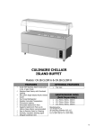
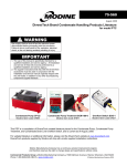
Installation, Maintenance, & Operation Guide
400 SERIES
Case Family Type:
CVT-D, CVT-CVXP, CVT-GV,
CVT-BWD, CVT-BGV, CVT-VE
Service / Self-Service Combination Merchandisers
800.552.6283 | southerncasearts.com
Table of Contents
General Information
Case Diagrams & Mechanicals
Receiving Cases
Apparent Loss or Damage
Concealed Loss or Damage
Exterior Loading
Handling of Cases
Store Conditions
General Information
Qualifying Case Standards
Control Information
2-3
4
4
4
4
4
4
5
6
8
8
8
8
9
9
9
10
10
Electrical Information
Wiring Diagrams
11-13
Refrigeration Information
Superheat Settings
BTU Information
Defrost Settings
Electrical Ratings
16
17
18
19
Optional Equipment
Condensate Pumps
Humidification System
20-21
22-24
Air Flow & Product Loading
Installation Instructions
Locate Area of Placement
Marking Area on Floor
Leveling
Roll Case into Place
Set Other Cases into Place
Join Cases
Bolt Cases Together
Case Mechanical Connections
Shelving
General Information
Diagrams
Parameter Information
Default Control Settings
14-15
14
14
14
General Information & Diagram
26
Maintenance & Care Information
General Care and Cleaning
Exterior Surfaces
Interior Surfaces
Case Cleaning & Maintenance
Cleaning Honeycomb Assembly
Cleaning Plexiglass
Maintenance Schedule
27
27
27
27
27
27
28-29
Service
Trouble-Shooting Guide
Service Department
Parts
Maintenance Records
Limited Warranty & Compliance
Limited Warranty Imformation
Liabilty Notice
30-31
32
32
33-34
35
36
Important Reminder!!!
Keep This Guide For
Future Reference!
275 Drexel Road S.E.
Bessemer, AL 35022
Phone: 800.552.6283
Fax: 205.428.2552
southerncasearts.com
© 2014, Southern CaseArts, Inc. is a Southern Store Fixtures, Inc. company 800.552.6283
Page 1
Case Diagrams & Mechanicals
Section Views
Page 2
© 2014, Southern CaseArts, Inc. is a Southern Store Fixtures, Inc. company 800.552.6283
Case Diagrams & Mechanicals
CVT-CVXP
CVT-D, DC
CVT-GV, GVC
CVT-BWD, BWDC
CVT-VE
CVT-BGV, BGVC
Plan Views
© 2014, Southern CaseArts, Inc. is a Southern Store Fixtures, Inc. company 800.552.6283
Page 3
General Information
Receiving Cases
Transportation companies assume all liability from the time a shipment is received by them until the
time it is delivered to the consumer. Southern CaseArts, Inc liability ceases at the time of shipment.
All equipment should be thoroughly examined for shipping damage and/or shortages before and
during unloading. This equipment has been carefully inspected at our factory. Any claim for loss
or damage must be made to the carrier. The carrier will provide any necessary inspection reports
and/or claim forms. For information on shortages, please contact the service parts department at
800.552.6283.
Apparent Loss or Damage
If there is an obvious loss or damage, it must be 1) noted on either the freight bill or the express
receipt and 2) signed by the carrier’s agent; otherwise, the carrier may refuse the claim.
Concealed Loss or Damage
When loss or damage is not apparent until after the equipment is unpacked or uncrated, retain
all packing materials and submit a written request to the carrier for inspection within 15 days of
receipt of equipment.
Exterior Loading
DO NOT WALK OR STAND ON TOP OF DECKS, SHELVES, OR CASES FOR ANY REASON or
damage to the cases and serious personal injury could occur. THEY ARE NOT STRUCTURALLY
DESIGNED TO SUPPORT EXCESSIVE EXTERNAL LOADING such as the weight of a person. DO
NOT PLACE HEAVY OBJECTS ON THE CASE. If work is to be done above the fixture then ladders and/or scaffolding must be used.
Handling of Cases
Southern CaseArts’ remote series of cases are shipped to stores with dollies on casters placed
beneath the base frame. From loading to unloading and placement to installation, we strive to
ensure that moving our cases is easy for everyone involved. In most instances, one or two persons
can move the cases with ease. Our self-contained series of cases, unless otherwise specified
when ordering, are generally manufactured with heavy-duty casters mounted permanently to the
base frame for ease of mobility when unloading and when moving around for placement in the
store. If a forklift or pallet jack is used to move the case, use a spotter to guide forks in place to
prevent damage to electrical, plumbing, and refrigeration lines. DO NOT PUSH OR PULL ON
ANY GLASS COMPONENTS OF THE CASE. Glass breakage may result in serious injury.
Store Conditions
Southern CaseArts’ refrigerated standard display cases are designed for use in Class 1 air-conditioned stores, where the temperature does not exceed 75° F and the relative humidity does not
exceed 55%.
Air conditioning, fans, ovens, drafts, direct sunlight or anything that could disturb the air inside the
case could result in poor performance.
General Information
Display cases described in this operation guide are part of the 200 series of product displays
provided by Southern CaseArts, Inc. This guide covers the following product display models:
SCS. These cases are not designed to cool down products but are designed to maintain the safe
temperature of the product once placed in the case.
Page 4
© 2014, Southern CaseArts, Inc. is a Southern Store Fixtures, Inc. company 800.552.6283
General Information
•
•
•
•
•
•
•
•
•
•
•
•
•
•
•
•
•
Keep products at food safe temperature prior to loading them into the case.
Allow the case to operate a minimum of 4 hours before loading with product.
Do not place any product into a display case until it is at operating temperature.
Fresh meat should not be put into the case above 40° core temperature. This lowers the
quality of the meat very rapidly.
Setting temperature too cold can cause product dehydration.
Products should be rotated at a minimum of every 4 hours.
Discharge air plenum and return air grill must not be blocked or restricted - the case may not
operate properly. Overloading the case may impair the proper operation of the case.
For self-contained models, the air intake grill and discharge vent must be clear of obstructions
or the case will not operate properly. The air intake grill has an air filter that needs to be
cleaned monthly or more frequently if required.
For cases equipped with an electric condensate dissipater pan. Electric dissipater pans are
meant solely for the purpose of evaporating condensate water released from the refrigeration
coil during the defrost cycle. Dust, food products, grease, caustic liquids, flammable
materials, wash water and/or cleaning chemicals should not be allowed to accumulate in the
pan. Regular monthly maintenance should be performed to make sure the pan is clean and
the float switch moves up and down freely. Failure to follow these guidelines could result in
flooding, overheating, and/or a fire hazard, all of which will void the warranty.
These cases require a dedicated circuit with proper sized wire for the distance from the
electric panel.
Cases equipped with electric dissipater pans should never have food products washed or
poured into the case tub drain, as it will result in damage to the heating element.
DO NOT WASH OUT THE CASE WITH CAUSTIC CHEMICALS unless the case is attached
to a floor drain. Many cleaning chemicals will dissolve the heater elements in the electric
evaporator pans.
Southern CaseArts’ refrigerated standard display cases are designed for use in air conditioned
stores, where the temperature and relative humidity do not exceed 75° F and 55% RH.
When utilizing refrigerated self-service or open case merchandising, the following should be
considered: 1) Air conditioning ducts that are positioned or blowing directly into an open
case will impair case performance. Also, any air current from prep areas or ceiling fans can
impair the performance of a case. 2) Ovens or other forced-air heating systems placed near
the case can affect the case air curtain and impair the temperature performance of the case.
DO NOT WALK ON TOP OF THE CASE. These cases are not designed or built in standard
models to support extra weight on top. Heavy weight placed on top of the case may cause
damage to the case as well as personal injury.
DO NOT TILT SELF-CONTAINED CASES more than 15° from vertical when setting in place.
Compressors may be damaged. Compressor warranty may be voided. If the self-contained
case has been tilted, wait at least 24 hours before turning the case on.
DO NOT USE RUNNING WATER ON CASES EQUIPPED WITH A CONDENSATE PUMP.
It is important to not introduce more water than the case condesate pump can handle.
The case must be routinely wiped out and cleaned by hand or the pump can be damaged
and cause flooding or personal injury. See care instructions for these pumps in optional
equipment.
© 2014, Southern CaseArts, Inc. is a Southern Store Fixtures, Inc. company 800.552.6283
Page 5
General Information
WARNING
Use caution and keep hands
out of the way when lifting the
case to remove dolly! FAILURE
TO DO SO COULD RESULT IN
SERIOUS INJURY!
These cases, unless otherwise specified
are shipped on dollies for ease of
unloading. If the loading dock is level
with the truck, the cases can be rolled off
the truck and into the store.
CAUTION
Be careful around pinch
points they can cause bodily
harm!
When moving a case without casters into
position, it is recommended to only use
a jack bar and dollies. Cases have a wide
variety of electrical , drain and refrigerant
connections under the case and may be
damaged by moving the cases.
Case Industry Standards
The 400 Family of cases conform to the following standards:
Installation Instructions
WARNING
Do not push or pull on any glass
components of the case. Glass
breakage may result in serious injury!
IMPORTANT
If forklifts or pallet jacks are used
to move cases, use a spotter to
guide forks into place to prevent
damage to electrical, plumbing, and
refrigeration lines.
Page 6
Southern CaseArts’ remote series of cases
are shipped to stores with dollies on casters
placed beneath the base frame. From loading
to unloading and placement to installation,
we strive to ensure that moving the cases is
easy for everyone involved. In most instances,
one or two people may move the cases with
ease. Our self-contained series of cases,
unless otherwise specified when ordering, are
generally always manufactured with heavyduty casters mounted permanently to the base
frame for ease of mobility when unloading
and when moving around for placement in the
store. If a forklift or pallet jack is used to move
cases use a spotter to guide forks into place to
prevent damage to electrical, plumbing, and
refrigeration lines. DO NOT PUSH OR PULL
ON ANY GLASS COMPONENTS OF THE
CASE. Glass breakage may result in serious
injury.
© 2014, Southern CaseArts, Inc. is a Southern Store Fixtures, Inc. company 800.552.6283
Installation Instructions
WARNING
Do not place self-contained version
of this unit equipped with an electric
evaporator pan near or under any
flammable structure or flammable
merchandise! This could result in a fire
hazard !
CAUTION
Do NOT walk on top of the case. These
cases are not designed or built in standard
models to support extra weight on top.
Heavy weight placed on top of the case
may cause damage to the case as well as
personal injury.
IMPORTANT
IT IS THE INSTALLERS RESPONSIBILITY
TO INSTALL CASE TO MEET ALL LOCAL
BUILDING AND HEALTH CODES.
IMPORTANT
BEFORE STARTING THE UP THE
CASE, CHECK ALL ELECTRICAL
CONNECTIONS.
Southern CaseArts’ refrigerated standard display cases are designed for use in air-conditioned stores, where the temperature does not
exceed 75° F and the relative humidity does not
exceed 55%.
Air conditioning, fans, ovens, spot lights, direct
sunlight or anything that could disturb the airflow inside the case could result in poor performance.
DO NOT WALK OR STAND ON TOP OF
DECKS, SHELVES, OR CASES FOR ANY
REASON and serious personal injury could
occur. THEY ARE NOT STRUCTURALLY DESIGNED TO SUPPORT EXCESSIVE EXTERNAL LOADING such as the weight of a person.
DO NOT PLACE HEAVY OBJECTS ON THE
CASE. If work is to be done above the fixture
then ladders and/or scaffolding must be used.
IMPORTANT
If the correct lift points are not identified
prior to removal. Look for the supports
under the unit before removing pallet.If
not removed, it will damage the finished
metal.
IMPORTANT
Installation of 3rd-party material may
result in improper case performance
IMPORTANT
Remove all styrofoam shipping blocks
from case. Failure could result in case
damage.
© 2014, Southern CaseArts, Inc. is a Southern Store Fixtures, Inc. company 800.552.6283
Page 7
Installation Instructions
1
2
Locate and verify placement of cases inside
the store building. Unload and move cases
as close as possible to their final location.
Verify that no changes have been made to
area and that blueprints are still current. Find
points of reference to take dimensions to
help locate the cases.
3
4
Leveling is very important and necessary
to ensure proper case alignment when
installing. Improper leveling can affect
the refrigeration systems and lead to
improper drainage of defrost water. To
ensure proper leveling, locate the highest
point on the chalk line as a reference to
determine the height the leveler legs need
adjusting.
Page 8
Mark the floor where cases are to be located
for the entire lineup.
Roll the first case into position. Use a jack bar
and place it on the underside of the heavyduty steel frame to lift the case and remove
all dollies. CAUTION - KEEP HANDS OUT
OF THE WAY AT ALL TIMES TO AVOID
INJURY.
© 2014, Southern CaseArts, Inc. is a Southern Store Fixtures, Inc. company 800.552.6283
Installation Instructions
5
Roll the next case into position leaving a few
feet in between from the adjoining case for
maneuvering. Repeat step 4 for removing
dollies from beneath the case. CAUTION KEEP HANDS OUT OF THE WAY AT ALL
TIMES TO AVOID INJURY.
7
MAKE SURE AND LEVEL ALL CASES. For
shipment, the leveler legs on the cases are
run all the way out. IT IS VERY IMPORTANT
TO SCREW THE LEVELER LEGS ALL THE
WAY IN BEFORE LEVELING THE CASE.
WHEN THE CASE IS LEVEL MAKE SURE
ALL THE LEVELER LEGS ARE SECURE
TO THE FLOOR.
6
Remove anything from the case that could
interfere with the case joining. Run a bead
of sealant around the entire end before
pushing cases together tightly. Make sure all
alignment pins are in place before running
a bead of sealant and pushing the case
together.
8
Push cases tightly together and bolt them
through the holes provided. Tighten until all
margins are equal. DO NOT OVER TIGHTEN.
Repeat steps 4-8 until entire line-up is set.
© 2014, Southern CaseArts, Inc. is a Southern Store Fixtures, Inc. company 800.552.6283
Page 9
Installation Instructions
10
9
Make sure all the glass opens and closes
correctly. If the glass binds or overlaps each
other the case may not be level. Make sure
all the shelves are securely in position and
the plugs for the shelf lights are plugged in
all the way. Install any joint caps sent with
the case.
WARNING
Make sure all shelves with lights are
plugged in all the way and seated
completely. Unused receptacles
must have the cover pushed all
the way in and seated completely!
Failure to do this could result in
arcing, possible fire, or safety
hazzards!
IMPORTANT
ON CASES EQUIPPED WITH RADUIS
HARDWARE, YOU CAN ONLY OPEN
ONE PIECE OF FRONT SERVICE
GLASS AT A TIME ON THE CURVES IN
THE LINEUP! FAILURE TO DO SO WILL
DAMAGE THE HARDWARE!
Page 10
After the mechanical connections are made
all penetrations must be sealed and all
panels and kick plates must be installed.
If 90% of the floor under case cannot be
accessed by a 1.5” diameter rod for cleaning
then silicone kickplate to floor.
IMPORTANT
AFTER INSTALLATION IS COMPLETE,
RUN THE CASE AT NORMAL
OPERATING TEMPERATURE BEFORE
TIGHTENING THE SCREWS IN THE
GLASS CLAMP. THERMAL EXPANSION
CAN CAUSE THESE TO LOOSEN.
IMPORTANT
That all the piping connections are
compliant with local codes.
IMPORTANT
Necessary when brazing wet rag
around the area to avoid any damage.
© 2014, Southern CaseArts, Inc. is a Southern Store Fixtures, Inc. company 800.552.6283
Electrical Information
© 2014, Southern CaseArts, Inc. is a Southern Store Fixtures, Inc. company 800.552.6283
Page 11
Electrical Information
Page 12
© 2014, Southern CaseArts, Inc. is a Southern Store Fixtures, Inc. company 800.552.6283
Electrical Information
© 2014, Southern CaseArts, Inc. is a Southern Store Fixtures, Inc. company 800.552.6283
Page 13
Factory Settings
REFRIGERATIONDATA
(THESESETTINGARESUBJECTTOCHANGEWITHOUTNOTICE)
MODEL
Btuh/Ft*
EVAP
CVTͲDSERVICE
CVTͲDSELFSERVE
CVTͲCVXPSERVICE
CVTͲCVXPSELFSERVE
CVTͲGVSERVICE(G/C)
CVTͲGVSELFSERVE
CVTͲBWDSERVICE
CVTͲBWDSELFSERVE
CVTͲBGVDOME(G/C)
CVTͲBGVSELFSERVE
CVTͲVE
350
500
400
500
400
500
400
500
400
500
900
24°
24°
24°
24°
24°/30°
24°
24°
24°
24°/30°
24°
24°
SUCTION SUPERHEAT DEF.TERM,FAILͲSAFE
22°
22°
22°
22°
22°
22°
22°
22°
22°
22°
22°
5°Ͳ7°
5°Ͳ7°
5°Ͳ7°
5°Ͳ7°
5°Ͳ7°
5°Ͳ7°
5°Ͳ7°
5°Ͳ7°
5°Ͳ7°
5°Ͳ7°
5°Ͳ7°
47°,40MIN.
47°,40MIN.
47°,40MIN.
47°,40MIN.
52°,60MIN.
47°,40MIN.
47°,40MIN.
47°,40MIN.
52°,60MIN.
47°,40MIN.
47°,40MIN.
#PERDAY
4
4
4
4
2
4
4
4
2
4
4
*WILLCHANGEDEPENDINGONLIGHTS,ANTIͲSWEATS,ANDAPPLICATION(THESEAREFORADELI
APPLICATIONEXCEPTTHEGVANDBGVVERSIONSOFTHESECASESAREFORFRESHMEAT/SEAFOOD).
ELECTRICALDATA
115VOLTREMOTE
MODEL
LIGHTS3'
FANS3'
LIGHTS4'
FANS4'
LIGHTS5'
FANS5'
ANTIͲSWEAT
CVTͲD
CVTͲCVXP
CVTͲGV
CVTͲBWD
CVTͲBGV
CVTͲVE
0.75
0.78
0.75
0.93
0.75
0.75
0.6
0.6
0.36
0.6
0.6
0.36
0.96
1
0.96
1.19
0.96
0.96
0.6
0.6
0.36
0.6
0.6
0.36
1.2
1.24
1.2
1.49
1.2
1.2
0.6
0.6
0.36
0.6
0.6
0.36
0.72
ͲͲͲ
1.02
0.72
1.02
0.72
MODEL
LIGHTS6'
FANS6'
LIGHTS8'
FANS8'
LIGHTS12'
CVTͲD
1.5
0.9
1.92
1.2
CVTͲCVXP
1.56
0.9
2
1.2
CVTͲGV
1.5
0.51
1.92
0.68
CVTͲBWD
1.86
0.9
2.38
1.2
CVTͲBGV
1.5
0.9
1.92
1.2
CVTͲVE
1.5
0.51
1.92
0.68
LIGHTAMPERAGESMAYVARYDEPENDINGONAVAILABLEOPTIONS
Page 14
2.88
3
2.88
3.57
2.88
2.88
FANS12' ANTIͲSWEAT
1.8
1.8
1.02
1.8
1.8
1.02
0.72
ͲͲͲ
1.02
0.72
1.02
0.72
© 2014, Southern CaseArts, Inc. is a Southern Store Fixtures, Inc. company 800.552.6283
Mechanical Expansion Valve and Superheat
CAUTION
During service of this equipment ,precautions should be taken to prevent loss of refrigerant
to the atomosphere. Always install the expansion valve stem cap after making valve adjustments.
Setting Superheat
The expansion valve furnished with your case has been sized for for maximum coil efficiency . To adjust
superheat, perform the following:
1. Place a thermocouple near the expansion valve bulb .Read the suction line pressure as near coil as
possible. If closest is at the condenising unit ,estimate suction line loss at 2 PSIG.
2. Convert coil suction pressure to temperature .The difference between coil temperature and the
temperature is superheat. Use average superheat when expansion valve is hunting.
3. Do not set the superheat until cases have pulled down to operating temperature and never open or
close the valve over1/4 turn between adjustments and allow 10 minutes or more between adjustments.
4. Superheat should be set at 6-8°F.
5. After the initial setting ,the superheat should be rechecked when product is stocked and at designed
temperture.
Superheat Calculations
EXAMPLE:R404
+33F Suction temperature
+28F Suction pressure converted to temperature
=+5FSuperheat
© 2014, Southern CaseArts, Inc. is a Southern Store Fixtures, Inc. company 800.552.6283
Page 15
Control Information
2. General Description
easy and easy compact are electronic microprocessor controllers with LED display,
developed for the management of refrigerating units, display cabinets and
showcases. They exploit the experience and the success of the previous PJ32 range,
with the objective of offering a product that is simpler and more economical. The
structure of the parameters has been enhanced with new functions for more
dynamic and effective management of the temperature control and defrost.
digital electronic thermostats with defrost controls
1. GENERAL WARNING
2. GENERAL DESCRIPTION
3. ASSEMBLY AND INSTALLATION
3.1 REAR PANEL INSTALLATION AND REMOVAL
3.2 FRONT PANEL INSTALLATION AND REMOVAL
3.3 WIRING DIAGRAM
4. USER INTERFACE AND STARTUP
4.1 DISPLAY
4.2 KEYPAD FUNCTIONS
5. PRELIMINARY CONFIGURATIONS
6. NAVIGATING PARAMETERS
7. SETTING PARAMETERS
8. PROGRAMMING KEY
1
1
1
1
1
2
2
2
2
3
3
3
4
1. General Warning
CAREL bases the development of its products on decades of experience in HVAC, on the
continuous investments in technological innovations to products, procedures and strict
quality processes with in-circuit and functional testing on 100% of its products, and on the
most innovative production technology available on the market. CAREL and its subsidiaries
nonetheless cannot guarantee that all the aspects of the product and the software included
with the product respond to the requirements of the final application, despite the product
being developed according to start-of-the-art techniques. The customer (manufacturer,
developer or installer of the final equipment) accepts all liability and risk relating to the
configuration of the product in order to reach the expected results in relation to the specific
final installation and/or equipment. CAREL may, based on specific agreements, acts as a
consultant for the positive commissioning of the final unit/application, however, in no case
does it accept liability for the correct operation of the final equipment/system.
Operation of the Carel product is specified in the technical documentation supplied with the
product or can be downloaded, even prior to purchase, from the website www.carel.com.
Each CAREL product, in relation to its advanced level of technology, requires setup/
configuration/programming/commissioning to be able to operate in the best possible way
for the specific application. The failure to complete such operations, which are required/
indicated in the user manual, may cause the final product to malfunction; CAREL accepts no
liability in such cases.
Only qualified personnel may install or carry out technical service on the product.
The customer must only use the product in the manner described in the documentation
relating to the product.
In addition to observing any further warnings described in the manual, the following
warnings must be heeded for all CAREL products
• prevent the electronic circuits from getting wet. Rain, humidity and all types of liquids
or condensate contain corrosive minerals that may damage the electronic circuits. In
any case, the product should be used or stored in environments that comply with the
temperature and humidity limits specified in the manual.
• do not install the device in particularly hot environments. Too high temperatures may
reduce the life of electronic devices, damage them and deform or melt the plastic parts.
In any case, the product should be used or stored in environments that comply with the
temperature and humidity limits specified in the manual.
• do not attempt to open the device in any way other than described in the manual.
• do not drop, hit or shake the device, as the internal circuits and mechanisms may be
irreparably damaged.
• do not use corrosive chemicals, solvents or aggressive detergents to clean the device.
• do not use the product for applications other than those specified in the technical
manual.
3. Assembly and Installation
3.1 Panel installation using 2 rear brackets (Fig. 3.a)
• insert the instrument in the opening; 1
• secure the instrument by sliding the brackets in the guides on the instrument
until compressing them against the panel 2
2
1
PUSH
PJ Easy / Easy Compact
Fig. 3.a
Removing from the panel with brackets
• release the instrument by pressing both brackets where marked “push” and sliding
it back on the guides.
3.2 Panel installation from the front using screws (Fig. 3.b)
• the thickness of the fastening panel must not exceed .12 inch;
• remove the front frame and make sure that the two catches are in place (these
must not protrude from the outline of the drilling template). If necessary, unscrew
the two screws. Do not unscrew excessively, the screws must not be detached
from the front panel 1
• insert the instrument in the opening in the panel and hold it in position by the
center of the front panel 1
• using the screwdriver, tighten the bottom screw 90°. The catch must come out
of its slot and click onto the panel, then tighten until the front panel is secure; Do
not over-tighten. When the front panel is secured, simply make another ½ turn
to compress the gasket. If the catch does not click onto the panel, unscrew the
screw, applying pressure at the same time with the screwdriver so that the catch
moves back. Do not unscrew too much, the head of the screw must not be raised
from the surface of the front panel 2
• repeat the same operation for the top screw 2
• apply the front frame 3
2
1
3
( )
*
max .12
All of the above suggestions likewise apply to the controllers, serial boards, programming
keys or any other accessory in the CAREL product portfolio.
(*) do not over-tighten the screws.
The technical specifications shown may be changed without prior warning.
• unclip the front frame;
• unscrew the bottom screw, at the moment the front panel detaches from the
panel, keep pressure on the screw and unscrew a further 90° to make the catch
go back into its slot;
• repeat for the top screw;
• remove the instrument from panel, keeping it horizontal
The liability of CAREL in relation to its products is specified in the CAREL general contract
conditions, available on the website www.carel.com and/or by specific agreements with
customers; specifically, to the extent where allowed by applicable legislation, in no case will
CAREL, its employees or subsidiaries be liable for any lost earnings or sales, losses of data and
information, costs of replacement goods or services, damage to things or people, downtime
or any direct, indirect, incidental, actual, punitive, exemplary, special or consequential damage
of any kind whatsoever, whether contractual, extra-contractual or due to negligence, or any
other liabilities deriving from the installation, use or impossibility to use the product, even if
CAREL or its subsidiaries are warned of the possibility of such damage.
Page 16
Fig. 3.b
CAREL adopts a policy of continual development. Consequently, CAREL reserves the right
to make changes and improvements to any product described in this document without
prior warning.
Dismantling using the screws from the front
© 2014, Southern CaseArts, Inc. is a Southern Store Fixtures, Inc. company 800.552.6283
Control Settings
3.3 Wiring Diagram
1
PJEZ(S, X)*
SERIAL
CONV
NTC/PTC
PROBES
DEF. T.
8 9 10 11
-10T50
SERIAL
CONV
NTC/PTC
PROBES
L
or
PJEZ(M)*
N
230Vac or
115 Vac or
12 Vac/Vdc
AUX
L
N
-10T50
SERIAL
CONV
NTC/PTC
PROBES
L
N
230Vac or
115 Vac or
12 Vac/Vdc
function
1
compressor
2
digits
normal operation
start up
ON
OFF
flash
on
off
call
ON
two digits with sign and decimal point, -99 to 99(*).
See parameters /4, /5, /6 for the type of probe
displayed, values in °C/°F and decimal point
PROG.
KEY
4.2 Keypad Functions
or
Keypad functions for easy and easy compact models C, S, X, Y
1
8 9 10 11
DEF. T.
AUX
L
N
6 7
AMB. T.
1 2 3 4 5
but. no.
8 9 10 11
DEF. T.
6 7
AMB. T.
1 2 3 4 5
PROG.
KEY
or
DI / PROBE
N
230Vac or
115 Vac or
12 Vac/Vdc
AUX
L
N
PJEZ(C, Y)*
6 7
L
or
AMB. T.
1 2 3 4 5
PROG.
KEY
DI / PROBE
2
-10T50
DI / PROBE
Easy
2
or
3
Easy Compact
PJEZS***E**
PJEZS***0**
PJEZS***1**
no.
NTC PROBES
1 2 3
L
PROG. SERIAL
KEY
CONV
4 5 6
NTC PROBES
1 2 3
N
L
4 5
N
1
PJEZM*N*E**
PJEZM*N*0**
PJEZM*N*1**
NTC PROBES
1 2
L
PROG. SERIAL
KEY
CONV
NTC PROBES
N
L
12V~
2
3 4
1 2
3 4 5
N
12V~
3
PJEZM*P*E**
PJEZM*P*0**
PJEZM*P*1**
NTC PROBES
1 2 3
PROG. SERIAL
KEY
CONV
4 5 6
AUX
normal operation
pressing the button
pressing with other
alone
buttons
pressed together
more than 3 s: switch
with 3 activates
ON/OFF
/deactivates the
continuous cycle
- 1 s: displays/sets the
set point
- more than 3 s:
accesses the parameter
setting menu (enter
password 22)
- mutes the audible
alarm (buzzer)
more than 3 s: activates pressed together
/deactivates the defrost with 1 activates
/deactivates the
continuous cycle
start up
-
for 1 s
RESET
current EZY
set
pressed together
(2 and 3) activate
parameter reset
procedure
for 1 s
displays
firmware
version
NTC PROBES
1 2 3
3 4
AUX
L
N
L
N
Keypad functions for easy and easy compact M models (models
with keypad only)
4. User Interface and Startup
4.1 Display
1
1
7
2
2
3
4
3
5
6
Fig.
no.
1
2
3
4
5
function
compressor
fan
defrost
auxiliary
output (AUX)
clock (RTC)
6
alarm
7
digits
normal operation
ON
on
on
on
OFF
off
off
off
output active
output not active -
ON
RTC available,
enabled (tEN=1)
and at least one
time band has
been set
RTC not available
or not enabled
(tEN=0) or no
time band set
ON (if
the
clock
is
fitted)
flash
call
call
call
start
up
ON
ON
ON
no alarm in
alarm in progress
ON
progress
three digits with decimal point and range -199 to
999. See parameters /4, /5, /6 for the type of probe
displayed, values in °C/°F and decimal point
no.
1
2
3
normal operation
start up
pressing the button alone
more than 3 s: switch ON/OFF
- 1 s: displays/sets the set point
pressed together
- more than 3 s: accesses the parameter
activate parameter
setting menu (enter password 22)
reset procedure
- mutes the audible alarm (buzzer)
for 1 s displays
rapid selection of probe displayed
firmware
version
© 2014, Southern CaseArts, Inc. is a Southern Store Fixtures, Inc. company 800.552.6283
Page 17
Control Information
5. Preliminary Configurations
The dAY, hr, Min parameters are not restored, as these are saved instantly when
entered.
Once the electrical connections have been completed, simply power-up the
controller to make it operative.
CAREL then recommends checking that the display does not show any alarm
signals, then set the time and date, and finally set the parameters as desired. The
main parameters are as follows:
Category
Probe parameters
Control parameters
Compressor parameters
Control parameters
st
set point
rd
set point differential
Defrost parameters
d0
type of defrost
dl
interval between two defrosts
dt
end defrost temperature
dP
maximum defrost duration
Alarm parameters
Ad
temperature alarm delay
AL
low temperature alarm threshold/deviation
AH
high temperature alarm threshold/deviation
6. Navigating Parameters
• press the SET button for more than 3 s (if there are active alarms, mute the
buzzer), the display shows the parameter code “PS” (password);
• press the SET button to access the password setting;
• use the UP and DOWN buttons to scroll the numbers until displaying “22”
(password to access the parameters);
• press the SET button to confirm the password;
• use the UP and DOWN buttons to scroll the parameters. The LED corresponding
to the category of parameters will be on (see Table 5.b);
• press SET to display the value associated with the parameter
• increase or decrease the value using the UP or DOWN button respectively;
• press SET to temporarily save the new value and display the parameter again;
• repeat the procedure for any other parameters that need to be modified;
• press the SET button for more than 3 s to permanently save the parameters and
exit the parameter setting procedure.
d
Alarm parameters
A
Fan parameters
F
AUX output configuration parameters
RTC parameters
H1
-
7.1 Quick Set Parameters
This is a basic list of parameters to quickly start a controller for both medium
(table 7.a) and low temperature units (table 7.b).
7.a For medium temperature applications
Parameter
/5
St
rd
dl
Description
Select °C / °F
Set Point
Control differential
Interval before defrosts
Setting
1
34
6
0
7.b For low temperature applications
Parameter
/5
St
rd
dl
• press the SET button for more than 3 s (if there are active alarms, mute the
buzzer), the display shows the parameter code ‘PS’ (password);
• use the UP and DOWN buttons to scroll the parameters. The LED corresponding
to the category of parameters will be on (see Table 5.b);
• press SET to display the value associated with the parameter
• increase or decrease the value using the UP or DOWN button respectively;
• press SET to temporarily save the new value and display the parameter again;
• repeat the procedure for any other parameters that need to be modified;
• press the SET button for more than 3 s to permanently save the parameters and
exit the parameter setting procedure.
Accessing the type C parameters:
Defrost parameters
Icon
-
7. Setting Parameters
The operating parameters, modifiable using the keypad, are divided into two
types: frequent (type F) and configuration (type C). Access to the latter is
protected by password (default= 22) to prevent accidental or unauthorized
modifications.
Accessing the type F parameters:
Initial
/
r
c
dt
dp
Description
Select °C / °F
Set Point
Control differential
Interval before defrosts
End defrost temperature set point/
defrost temperature threshold with
temp. control
maximum defrost duration
Setting
1
-5
6
6
45
25
7.2 Resetting to factory defaults
Warnings:
Running this procedure overwrites any custom parameter settings.
•
•
•
•
•
To reset the default parameters:
disconnect power from the instrument;
reconnect power while holding the SET and DOWN buttons;
the display will show the message “CF”;
after a few seconds the instrument starts operating with the default configuration.
Any different parameter settings will need to be updated.
Warnings:
If no button is pressed for 60 s, all the changes made to the parameters,
temporarily saved in the RAM, will be cancelled and the previous settings
restored.
If power is disconnected from the instrument before saving the settings
(pressing the SET button for 3 s), all the changes made to the parameters and
temporarily saved will be lost.
Page 18
© 2014, Southern CaseArts, Inc. is a Southern Store Fixtures, Inc. company 800.552.6283
Control Settings
Default Settings
Par.
Description
Type Min
M ax
UOM.
EZY
0 1 2 3
PS
/2
/4
/5
/6
/7
password
probe measurement stability
select probe displayed
select °C/°F
disable decimal point
enable probe 2 alarm (model M only)
set
set
set
F
C
F
C
C
C
F
F
F
0
1
1
0(°C)
0
0
-12.7
-12.7
-12.7
200
15
3
1(°F)
1
1
+12.7
+12.7
+12.7
0
(°C/°F)
(°C/°F
(°C/°F)
22
8
1
1
1
0
0
0
St
r1
r2
r3
r4
set point
minimum set point value
maximum set point value
select direct/reverse operation
night-time set point delta
erential
S
C
C
C
C
F
r1
-50
r1
0
-50
0
r2
r2
+150
2
+50
+19
°C/°F
°C/°F
°C/°F
°C/°F
°C/°F
20
60
0
0
4
c0
c1
compressor and fan start delay on power-up
minimum time between consecutive compressor starts
time
minimum compressor on time
compressor on time with duty setting
continuous cycle duration
temperature alarm bypass after continuous cycle
C
C
C
C
C
C
C
0
0
0
0
0
0
0
100
100
100
100
100
15
15
min
min
min
min
min
h
h
0
0
0
0
0
4
2
C
F
F
0
0
-50
4
199
+127
h/min (see dC)
°C/°F
0
4
47
dP
d4
d5
d6
dd
d8
d9
d/
dC
type of defrost
inter val between defrosts
end defrost temperature set point/defrost temperature
threshold with temp. control
maximum defrost duration
defrost when switching the instrument on
defrost delay on power-up or when enabled by digital input
freeze control temperature display during defrost
dripping time
alarm bypass time after defrost
defrost priority over compressor protectors
defrost probe reading (2)
time base
F
C
C
C
F
F
C
F
C
1
0
0
0
0
0
0
0
199
1
199
1
15
15
1
1
min/s (see dC)
min
min
h
°C/°F
-
40
0
0
0
1
1
0
0
AL
AH
Ad
erential
absolute/relative temperature for low temperature alarm
absolute/relative temperature for high temperature alarm
temperature alarm delay
C
F
F
C
-20
-50
-50
0
+20
150
150
199
°C/°F
°C/°F
°C/°F
min
0
10
60
30
Acd
digital input alarm delay
enable alarm “Ed” (end defrost by timeout)
set point dirty condenser alarm
erential temperature
dirty condenser alarm delay
C
C
C
C
C
0
0
-50
0.1
0
199
1
+150
20.0
250
min
°C/°F
°C/°F
min
0
0
0
0
0
H0
serial address
C
0
207
-
1
H2
H4
H5
enable keypad
disable buzzer
ID code (read-only)
C
C
F
0
0
0
1
1
199
-
1
0
-
c3
c4
cc
c6
d0
dI
dt
A7
A8
Ac
6 4
3
47 50 50
© 2014, Southern CaseArts, Inc. is a Southern Store Fixtures, Inc. company 800.552.6283
4
0
0
Page 19
Optional Equipment
Condensate
Pump
SAFETY WARNING
FOLLOW ALL SAFETY INFORMATION TO REDUCE POTENTIAL ELECTRICAL SHOCK.
DISCONNECT POWER BEFORE SERVICING UNIT. PUMP MUST BE PROPERLY GROUNDED.
NEVER USE THE PUMP TO MOVE FLAMMABLE LIQUIDS.
CP-22
CP-22LP
CP-22T
CP-22LPT
Rated
Voltage
120 Volts / 60 Hz
Rated
Current Draw
Head
Height
1.9 Amps
22 ft. maximum
Flow Rate
at Zero Head
1.6 GPM
NEVER USE THE PUMP IN AN EXPLOSIVE GAS ENVIRONMENT,
OR WHERE GAS FUMES OR VAPOR MAY BE PRESENT.
ALWAYS DISCONNECT THE POWER PRIOR TO MOVING,
ADJUSTING OR SERVICING THE PUMP OR ATTACHED SYSTEMS.
Power Source
Supply voltage and frequency must match what is shown on the pump
nameplate. Source voltages lower than rated supply can reduce performance and cause the pump to overheat.
Pump Installation
The pump has rubber feet to reduce noise and keep it in place during
operation.
Do not use this pump in the presence of spraying or standing water, it may
cause a shock. This pump is not suitable for use in Class I or Class II
(explosive gas or dust locations).
Do not cover the pump air vents. The pump is air cooled. Do not cover
the vent holes located on the top or sides of the pump housing. The pump
b
ti tank lthat lcollects th
i
t
d
The pump
hast adbuilt-in
the water
from
thetappliance.
the pump switches on and pumps the water to a remote location for
motor running and high water (alarm) conditions.
The pump is also equipped with a switch that activates when the water in
The switch also has an alarm terminal that may optionally be connected to
an audible alarm or remote indicator light to indicate a trouble condition.
Page 20
© 2014, Southern CaseArts, Inc. is a Southern Store Fixtures, Inc. company 800.552.6283
Optional Equipment
Outlets and Tubing Connections
DiversiTech “CVT” clear vinyl. Attach the tubing by pressing it over the
Route the tubing up and away from the pump; avoid compressing or
kinking the tubing. The tube route should be the shortest possible distance
from the pump to the building exterior or other drain location. For best
results the distance that the water must go UP should be shorter than the
distance that it goes DOWN. With the longer DOWN tubing, the length will
help siphon the condensate from the tank, speeding the pump out time.
Pump Operation
Apply power by plugging in the pump. Check for green LED indication the
Test Safety Switch operation (if used) to be sure that the A/C system shuts
part of its travel.
RUN will be indicated by the yellow RUN LED.
WARNING
DISCONNECT
POWER
BEFORE
CLEANING OR SERVICING THIS UNIT!
FAILURE TO DO SO COULD RESULT IN
SERIOUS INJURY OR DEATH
Pump Maintenance and Disassembly
Always disconnect power before performing maintenance. Pump and
deck may be removed from the tank by pushing tabs located on the tank
Periodically inspect the Pump tank to assure it is free of accumulated dirt or
sludge. Do not use solvent cleaners. Clean tank with soap and warm
water only. The check valve may be removed for cleaning or replacement by unscrewing with a 9/16 wrench. (illustration)
Clean inlet and outlet piping. Tubing may be cleared
of slime or debris instantly with a Wagner brand
Gallo Gun tool and Swoosh cartridges.
Add Pro-Treat Tabs to the tablet tray.
Reassemble system and check
for correct operation.
© 2014, Southern CaseArts, Inc. is a Southern Store Fixtures, Inc. company 800.552.6283
Page 21
Optional Equipment
Page 22
© 2014, Southern CaseArts, Inc. is a Southern Store Fixtures, Inc. company 800.552.6283
Optional Equipment
© 2014, Southern CaseArts, Inc. is a Southern Store Fixtures, Inc. company 800.552.6283
Page 23
Optional Equipment
Page 24
© 2014, Southern CaseArts, Inc. is a Southern Store Fixtures, Inc. company 800.552.6283
Optional Equipment
© 2014, Southern CaseArts, Inc. is a Southern Store Fixtures, Inc. company 800.552.6283
Page 25
Air Flow & Product Loading
General Information and Diagram
Cases have been designed with an air delivery system to provide maximum product capacity. It
is important that you DO NOT OVERLOAD THE FOOD PRODUCT DISPLAY so that it disrupts
the air delivery system. Overloading will cause the loss of proper temperature levels and will
result in a malfunction of the case, particularly when the discharge and return air sections are
covered. Please keep products within the load limits shown on this diagram.
Load Line
Case Diagram - Informational
Shelf Load Limits
8” Deep
200 lb
10” Deep
200 lb
12” Deep
200 lb
15” Deep
200 lb
18” Deep
200 lb
21” Deep
200 lb
Shelf Load Limits
The weight limits listed here are with the shelf level and the weight evenly distributed. Exceeding
these ratings could cause damage and/or bodily harm.
Page 26
© 2014, Southern CaseArts, Inc. is a Southern Store Fixtures, Inc. company 800.552.6283
Maintenance & Care Information
General Care and Cleaning
Long life and the satisfactory performance of any equipment is dependent upon the care it receives.
To ensure a long life, proper sanitation, and minimum maintenance costs, these cases should be
thoroughly cleaned, all debris removed, and the interiors wiped down weekly, at a minimum.
Exterior Surfaces
The exterior surfaces may be cleaned with a mild detergent and warm water to protect and maintain
their attractive finish. NEVER USE ABRASIVE CLEANSERS OR SCOURING PADS. We recommend
Murphy’s Oil Soap used per manufacturer’s directions for the cleaning of wood veneer surfaces on
refrigerated cases.
Interior Surfaces
The interior surfaces may be cleaned with most domestic detergents, ammonia based cleaners
and sanitizing solutions with no harm to the surface.
IMPORTANT
Case Cleaning and Maintenance
• DO NOT use abrasive cleansers and scouring pads, as these will mar the finish.
• DO NOT use solvent, oil or acidic-based cleaners on any interior surfaces.
• Remove all product and all loose debris to avoid clogging the waste outlet.
• Next, turn off refrigeration, then disconnect electrical power.
• Thoroughly clean all surfaces with soap, hot water and a cleaning cloth or sponge. DO NOT
USE STEAM OR HIGH WATER PRESSURE HOSES TO WASH THE INTERIOR. THESE WILL
DESTROY THE CASES’ SEALING, CAUSING LEAKS AND POOR PERFORMANCE.
• Take care to minimize direct contact between fan motors and cleaning or rinse water.
• Rinse with hot water and a cleaning cloth or sponge, but do NOT flood.
• NEVER INTRODUCE WATER TO SELF-CONTAINED CASES, CASES WITH EVAPORATOR
PAN OR CONDENSATE PUMP, OR FASTER THAN THE DRAIN OUTLET CAN REMOVE IT.
• Allow cases to dry before resuming operation. Then power can be restored to case.
• Do NOT use hot water on cold glass surfaces. This could cause the glass to shatterand could
result in personal injury. Glass fronts and ends should be warm before applying hot water.
Cleaning Honeycomb Assembly
Honeycombs should be cleaned when necessary. Dirty honeycombs will cause merchandisers to
perform poorly. The honeycombs may be cleaned with a vacuum cleaner. Soap and water may be
used if all water is removed from the honeycomb cells before replacing. Be careful not to damage
the honeycombs.
Plexiglass Cleaning
It is very important to utilize only the recommended method and products for cleaning plexiglass.
Improper cleaning not only degrades the quality of the surface but also accelerates the frequency of
required cleanings. Incorrect cleansers have a tendency of causing small scratches in the surface
which, over time, will appear as a haze in the plastic. We recommend using soft cotton cloths.
CAUTION
Fluorescent lamps contain mercury vapor which can be harmful if exposed. Make sure and
replace all lamps with the approved shatter shields. Visit http://www.epa.gov/osw/hazard/
wastetypes/universal/lamps/index.htm for more info.
© 2014, Southern CaseArts, Inc. is a Southern Store Fixtures, Inc. company 800.552.6283
Page 27
Maintenance & Care Information
Cleaning Non-glare Glass
Our non-glare glass receives a special coating on the glass surface. The special coating is applied
in a manner to ensure that the high optical clarity of the glass is maintained. To protect this special
coating and optical clarity, it is essential that the glass be kept clean. Glass Plus® or Windex® are
the only solutions recommended for use on non-glare glass. You should only clean with a micro
fiber cleaning cloth. Scotch-Brite and Spontex are two common manufacturers of these cloths. A
micro fiber cloth can clean the glass without the use of the solutions. Cleaning solutions should only
be used for tough jobs.
• NOTE - Once the glass has been damaged with improper solutions, it is irreparable.
• Special Directions - Certain precautions should be taken before cleaning the inside portion of
the lift up glass. We recommend that the glass be fully opened to prevent cleaning solution from
splashing onto the food products. While cleaning the cases we recommend that the non-glare
glass be fully opened and covered so that no cleaning solution will splash onto the non-glare
glass coating.
IMPORTANT
UNDER NO CIRCUMSTANCE should you use coarse paper towels, scouring pads, powders,
steel wool, steel fiber materials, blades, acidic detergents, highly alkaline detergents, or fluorine
based detergents to clean non-glare glass.
Air Sweep Fan Assembly
The fans are located on the bottom of the tub. These fans must be checked every three months to
make sure air can pass through them. If they are clogged remove any dust or debris. If proper airflow is not maintained then it could cause sweating glass and poor product visibility.
WARNING
Electric dissipater pans are meant solely for the purpose of evaporating condensate water
released from the refrigeration coil during the defrost cycle. Dust, food products, grease,
caustic liquids, flammable materials, wash water and/or cleaning chemicals should not be
allowed to accumulate in the pan. Regular monthly maintenance should be performed to
make sure the pan is clean and the float switch moves up and down freely. Failure to follow
these guidelines could result in flooding, overheating and/or a fire hazard, and will void the
warranty.
To keep your Southern CaseArts case operating at its best we suggest the following
maintenance schedule. The yearly service should be performed by a qualified service
technician. Before doing monthly or yearly servicing BE SURE TO DISCONNECT ALL
POWER SUPPLIES TO THE CASE!
The coil cover only lift out for an inspector or trained service provider. May result in damage of the refrigerant system
if removed by a untrained person.
WARNING
DISCONNECT POWER BEFORE CLEANING OR
SERVICING THIS UNIT! FAILURE TO DO SO
COULD RESULT IN SERIOUS INJURY OR DEATH
1. The cases should be wiped down daily and cleared of all debris.
2. The product placement within the cases should be checked to ensure proper air flow to all products.
3. Be sure the air return grill is not blocked and the discharge air is at a normal velocity.
4. Be sure the air filter on the condensing unit is not clogged or dirty.
Page 28
© 2014, Southern CaseArts, Inc. is a Southern Store Fixtures, Inc. company 800.552.6283
Maintenance & Care Information
MONTHLY cleaning should consist of:
1. The cases should be broken down and cleaned thoroughly.
2. Remove honeycomb holder and wash honeycomb.
3. Wipe fan blades and fan guards.
4. Vacuum tub, fan shrouds (top and bottom), and coils where possible.
5. Remove debris from drain and clean evaporator pan.
6. Take out the air filter for the condensing unit and wash thoroughly and replace.
ANNUAL system check-up and adjustment:
Compressor:
1. Check compressor for indications of flooding. Check and log suction, discharge, and
saturated liquid line temperatures.
2. Check temperature differential across liquid line drier.
3. Check operations pressures of refrigeration cycle, verify full sight glass during normal operation.
4. Check unit for excessive noise, vibration, and short cycling.
WARNING
Electrical:
1. Inspect, clean, and tighten all electrical components.
AFTER CLEANING
2. Check and document amp draw for the following:
OR MAINTENANCE:
A. Compressor.
ALL LIGHTING AND
B. Line voltage.
FAN (ELECTRICAL
C. Condensing fan motor amperage.
CONNECTIONS)
D. Inspect disconnect and fuses.
MUST BE DRIED AND
3. Check contactor for signs of burnt contacts.
FULLY SEATED TO
Condenser and evaporator fan motors:
AVOID ARCING OR
1. Check for proper rotation and operation.
POSSIBLE FIRE OR
2. Check fan blades for damage.
SAFETY HAZARDS.
3. Check motor mounts for damage.
4. Clean all dirt and debris from fan blades.
WARNING
5. Check for proper operation during both refrigeration and defrost.
6. Check bearing for vibration and noise.
When working in a case
7. Check fan motors for abnormal vibration and noise.
that the coil cover is reGeneral:
moved.Use extreme cau1. Perform coil cleaning on evaporator and condenser coils.
tion the coil contains many
2. Remove and clean honeycomb diffusers.
3. Check and adjust controls, defrost time clocks, and thermostats. sharp edges that can cut
your hand or arm.
4. Check superheat and adjust to proper setting if necessary.
5. Check for refrigeration leaks on all equipment. Leak check inside the cabinet.
6. Inspect and check operation of all safety controls.
7. Make sure all panels are secure and secure with screws where necessary.
8. Check and clean condensate drain lines and pans.
9. Check drain for proper trap installation and that trap is holding water.
10. Check for proper draining. Verify that all debris is clear and drain is working properly.
11. Check condensate pump for proper operation and clean by flushing with bleach.
12. Check for proper temperatures on all levels and sections of case, log temperatures.
13. Blow out dust from screens in plenums.
© 2014, Southern CaseArts, Inc. is a Southern Store Fixtures, Inc. company 800.552.6283
Page 29
Trouble Shooting Remote Cases
Trouble Shooting Remote Cases
We have prepared a listing of potential case problems and how to diagnose performance issues.
1. Is the expansion valve superheat set correctly at 5° - 7° Fahrenheit?
2. Is the product at proper temperature when it is received from the cooler for merchandising? These
cases are designed to maintain safe temperature once the product is placed in the case. However,
the cases are not designed to cool down the products from unsafe temperatures.
3. Always allow the cases to operate for a minimum of four hours before loading with product.
4. Regarding the actual merchandising of the products in the case:
A. Is the product or case decoration obstructing the air discharge or return air?
B. Is the product exceeding the load limit of the case?
C. Good judgement should be utilized concerning rotation of product.
D. On most cases (other than multi-level service cases) the load line or refrigerated zone can be
determined by drawing a line from the rear of the discharge air grill to the return air intake.
Everything under this line is considered within the refrigerated zone.
5. All deck pans should be seated properly in the base of the case with all fan plenums securely in
place. All fans must be operational.
6. For self-service open case merchandising please consider the following:
A. Air conditioning ducts blowing directly into an open case will impair the performance. Any air
current from prep areas or ceiling fans can also impair the performance of the cases.
B. Spotlights, ovens, or forced air heat systems placed near the cases can affect the case air curtain
and the temperature performance of the case.
7. Do NOT walk on top of the case.
8. Remote system problems that potentially impair case performance:
A. Evaporator temperatures should be maintained at settings specified for each case in our technical
manual.
B. Variations in liquid temperature affect the expansion valve performance. Are all of the sub-cooled
liquids maintained at a constant temperature?
C. Does the system have enough refrigerant to maintain all of the remote case applications?
D. It is essential that the specified defrost requirement for each case is followed to ensure product
integrity while at the same time defrosting the case efficiently.
E. It is recommended that liquid and suction lines are sized correctly for each case lineup.
F. If other cases are connected in combination, this could affect suction pressure.
G. EPR’s at the case or at the system must be set to maintain the proper evaporator temperatures.
Case temperatures are to be controlled by the factory T-stat or suction solenoid.
CAUTION
Do NOT walk on top of the case. These cases are not designed or built in standard models
to support extra weight on top. Heavy weight placed on top of the case may cause damage
to the case as well as personal injury.
Page 30
© 2014, Southern CaseArts, Inc. is a Southern Store Fixtures, Inc. company 800.552.6283
Trouble Shooting Self-Contained Cases
Trouble Shooting Self-Contained Refrigerated Cases
PROBLEM: WILL NOT HOLD TEMPERATURE
• Check the electronic thermostat setting.
• Is the air filter clogged or dirty?
• Are any air conditioner vents blowing into or toward the case? Are any spotlights shining
into the case?
• Is the case near a door?
• Is the case in direct sunlight?
• Is there cooking equipment or hood vent causing air currents?
• Is the ambient air above 75° F or 55% relative humidity?
• Is the condensing coil clean?
• Is the evaporator coil clean?
• Are the discharge or return air vents blocked?
PROBLEM: CASE LEAKS WATER ON FLOOR
•
•
•
•
•
Is the ambient air above 55% relative humidity?
Is case drain clogged?
Is evaporator pan (or condensate pump) overflowing?
The electric dissipater pan cannot handle being flushed with water from cleaning.
Cases equipped with electric dissipater pans should never have food products washed or
poured into the drain as it will result in damage to the heating element.
• Make sure all case joints and penetrations are sealed.
PROBLEM: CASE SWEATING
• Is the relative humidity above 55% and 75° F?
• Is the case near an open door or window?
• Is the air sweep working?
FOR SERVICE, PARTS AND WARRANTY INFORMATION CALL 800-552-6283
(Please have model and serial numbers ready. This information can be found on the name
plate of the case.)
© 2014, Southern CaseArts, Inc. is a Southern Store Fixtures, Inc. company 800.552.6283
Page 31
PARTS LEGEND
Page 32
© 2014, Southern CaseArts, Inc. is a Southern Store Fixtures, Inc. company 800.552.6283
MAINTENANCESCHEDULE
MONTHLY
PERFORMEDBY
COMPANY
DATE
NOTES
SEEUNDERMAINTENANCEANDCAREINFORMATIONINTHISMANUALFORMAINTENANCECHECKLIST
© 2014, Southern CaseArts, Inc. is a Southern Store Fixtures, Inc. company 800.552.6283
Page 33
MAINTENANCESCHEDULE
MONTHLY
PERFORMEDBY
PERFORMEDBY
COMPANY
COMPANY
DATE
MAINTENANCESCHEDULE
ANNUALLY
DATE
NOTES
NOTES
SEEUNDERMAINTENANCEANDCAREINFORMATIONINTHISMANUALFORMAINTENANCECHECKLIST
Page 34
© 2014, Southern CaseArts, Inc. is a Southern Store Fixtures, Inc. company 800.552.6283
Warranty & Compliance
Limited Warranty
TWELVE MONTH WARRANTY - SOUTHERN CASEARTS, INC.’S PRODUCTS ARE WARRANTED
TO BE FREE FROM DEFECTS IN MATERIAL AND WORKMANSHIP UNDER NORMAL USE
AND MAINTENANCE FOR A PERIOD OF TWELVE MONTHS FROM THE DATE OF ORIGINAL
SHIPMENT. A NEW OR REBUILT PART TO REPLACE ANY DEFECTIVE PART WILL BE PROVIDED
WITHOUT CHARGE, PROVIDED THE DEFECTIVE PART IS RETURNED TO SOUTHERN
CASEARTS, INC. THE REPLACEMENT PART ASSUMES THE UNUSED PORTION OF THE
WARRANTY.
This warranty does not include labor or other costs incurred for repairing, removing, installing,
shipping, servicing, or handling of either defective parts or replacement parts.
The twelve month warranty shall not apply to any of the following:
1. To any product or any part thereof which has been subject to accident, alteration, negligence,
misuse or abuse, operation on improper voltage, or which has not been operated or maintained
in accordance with the Southern CaseArts, Inc.’s recommendations, or if the serial number of
the unit has been altered, defaced, or removed.
2. When the product, or any part thereof, is damaged by fire, flood, or other act of God.
3. Outside the continental United States.
4. To labor cost for replacement of parts, or for freight, shipping expenses, sales tax or upgrading.
5. When the operation is impaired due to improper installation.
THIS PLAN DOES NOT COVER CONSEQUENTIAL DAMAGES. Southern CaseArts, Inc. shall
not be liable under any circumstances for any consequential damages of any kind, including
without limitation, loss of profit, use or revenue or additional labor cost, loss of refrigerant or
food products, or injury to person(s) or property caused by or resulting from any defective
products, material or parts, or for any delay in its performance hereunder due to causes beyond
its control.
This warranty is expressly in lieu of all other warranties, express or implied and all other
obligations or liabilities on Southern CaseArts, Inc.’s part. The obligation to repair or replace
parts or components determined to be defective in material or workmanship shall be Southern
CaseArts, Inc.’s only and entire liability whether based on tort, contract, warranty or any other
theory. Southern CaseArts, Inc. neither assumes nor authorizes any other person or entity to
assume for it any other liability in connection with any product(s). The foregoing shall constitute
the sole and exclusive liability of Southern CaseArts, Inc.
Customer’s acceptance and/or use of any Southern CaseArts, Inc. product(s) constitutes
customer’s acceptance of and agreement with all terms and provisions of this limited warranty.
MAIL CLAIM TO:
SOUTHERN CASEARTS, INC.
275 DREXEL ROAD S.E.
BESSEMER, AL. 35022
© 2014, Southern CaseArts, Inc. is a Southern Store Fixtures, Inc. company 800.552.6283
Page 35
Liabilty Notice
Shelf Lighting System
Southern CaseArts,inc will not be liable for any direct or indirect exposure to water or other liquids on
the shelf lighting system. The use of a water hose or misting system on a display case with shelf lighting can lead to a number of serious issue.This could cause electrical failures, electric shock,fire and
mold which could lead to injury death sickness and property damage.Do not use water hoses misting systems or any device that sprays liquid,on a display case with lighted shelves.The lighting
on the case is not designed to be exposed to water or other liquids. If a water hose or misting system
is used or installed Southern CaseArts will not be subject to any liabilities or obligations. Any personal
injury, death or property damage resulting from an electrical failure, fire ,electric shock or mold.Southern casearts shall not be subject to any obligation or liabilities from the above notice.
WARNING
Improper voltage on the DC power
supplies may damage the LED lamp.
WARNING
LED 12v DC power supply needs to be replaced with a 12v DC power supply. Led 24v DC
power supply need to be replaced with a 24v DC power supply. Never use a T5/T8 ballast of
any kind to replace 12v DC or 24v DC power supply. T5 /T8 ballasts are much higher voltage
and operate on AC not DC current. If a T5/T8 ballast is used for replacement to a DC power
supply it will damage the LED system and could cause injuries fire, or damage to case.
Page 36
© 2014, Southern CaseArts, Inc. is a Southern Store Fixtures, Inc. company 800.552.6283
275 Drexel Road S.E.
Bessemer, AL 35022
Phone: 800.552.6283
Fax: 205.428.2552
Your Exclusive Source for Innovative Food Displays
Installation, Maintenance,
& Operation Guide
P/N: LD-MN-0021-0113
© 2014, Southern CaseArts, Inc. is a Southern Store Fixtures, Inc. company 800.552.6283
southerncasearts.com