1
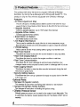
Please read this instruction manual carefully, and proceed with the
installation ONLY if you fully understand this manual. Make sure to pay
attention to all the "Important!" "Warning!" and "Cautionl" messages
through out Ule manuaL
r
1
/
Important!
• This product is legal for sale or use in California only on vehicles
which may never be driven on a public highway.
• This product is only for vehicles with 12V (battery) systems,
Warningl
• Installation and use of this product should only be performed by a
trained specialist, who is very familiar with the automObile's
mechanical. electrical, and fuel management systems. If installed
by untrained person, it may cause damage to the unit as well as the
vehicle.
• V\ihen using a soldering iron or other tools for installation, make
sure you read and understand the tool's user manual, Mis-use of
these tools can C<'!useserious injuries.
• Never tune the E~manage willle the vehicle is moving.
• Nevertune the e-Manageonpublic highways. This can be
dangerous to you and others on the road.
• When tuning and operating the vehicle in a garage, make sure that
the garage is equipped with a proper ventilation system,
• After installation and tuning, make sure to clean up every thing that
would interfere the driver. Wires, tools, and laptop computer may
interfere with the driver and cause accidents.
• Avoid open sparks, flames, or operation of electrical device
near flammable substances.
• Make sure there are no leaks in the fuel system and that a\1 of Ihe
connections are secure.
1
Caution!
• Improper tuning of the e-Maoage can cause damage to the ~e
• GReddv Performance Products. Inc. will not take an~ responsibilil:t:
of dam§ge caused by improper installation or tuning.
• Tuning should be performed only by a technician who fully
understand the vebicle's fuel management and ignition timio,fL
requirement for the engine being tuned.
• Always use a proger airlfuel ratio meter when tuning the e-Manage.
• Installation of this product requires modification of the vehicle's
electrical system.
• VVhen making wire connections, be sure to remove the key from the
ignition, and disconnect the negative terminal of the battery.
• Never short out the system. It can damage the unit as well as
the vehicle's electrical system.
• Read and fully understand the wiring dfagram before making any
wire connection.
• IMlen connecting the connector, push it In all the way untif you hear
them click in together.
• The communication cable is not a repairable item, so please take
care of it. \NIlen disconnecting from the PC (laptop), pullholding the
connector. Never pull on the cord.
Please
• The product and the instruction manual are subject to change
without notice.
2
-. ----..-c-:-::-:-:::"'-------------"'
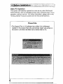
Please
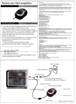
• Check the parts list and make sure you have received all the items
in the list.
L _____________________________.________
----........
-
~\
~. ~. !))
.•. ~
CO ROM x1
Communication Cable x1
...... "..,1·1.~ •• 1/... ,. .. '<-'f"
' ........ J:li·_V·
Instruction Manual x1
3
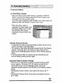
This product will allow the tuner to program GReddy e-Manage
functions, by linking the a-Manage and a Windows® based PC. This
product is only for the vehicles equipped with GReddy e-Manage.
Features:
• Air Flow Adjustment Map
This 16 x16 (rpm x throttle position) table 1s used to fine-tune the input
signal of the Air Flow Meter or MAP Sensor to the ECU for fuel enrichment.
• Upgrade Injectors
Conlrols upgrade injectors. (up to 150% larger than factory)
• Upgrade Airflow meters
controls upgrade Airflow meters .
• Boost limiter cut feature
Eliminates factory boost limiter.
• Anti Engine Stall feature
This is used to stabilize the rough idle due to turbocompres~;;br surge,
Bfow"offvalve vented out to the atmosphere or use of a high lift camshaft.
• VTEC® Setting
This is used to set the vtEC setting without going in to the Main Unit.
• Map Trace feature
This allows the tuner to pin point the current location on any map table,
• Real Time Display feature
This allows the tuner to monitor the engme condition in real time.
• Real Time Communication
This allows the PC and e-Manage to communicate at real time. Any
changes made on the computer screen is sent to a-Manage with in 2-$ sec.
• Data Logging feature
This allows the tuner to view the data recorded and saved during the real-
time mode in graph fonn.
• Security Setting feature
This allows the tuner set up a password to apply a security lock to the data
in the main unit.
Optional Parts:
• Harriess Kit (Injector control)
This harness is used when controlling main injectors or sub injectors
• Harness Kit (Ignition Timing Control)
This Harness is used when controlling the ignition timing.
, GReddy Pressure Sensor
GRaddy pressure sensor can be used for the scale of each Map table. Tilis
is used when the factory system e)(ceeds the Air Flow Meter or MAP sensor
capaciiy.
4
u
•
•
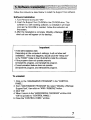
Before installation of the software, please make sure that the PC is set
up correctly. This product will only operate on Windows®95, 98, Me, 01'
2000, that meets the requirements listed below.
System Requirements
• lnteJ® Pentium® 166MHz or faster processor
• At least 32MB of RAM (64MB recommended)
• A hard drive with at least 50MB of free space.
• A SVGA monitor (8DOx600) and a16bit (high color) display
• A3.5inch 1.44MB floppy disk drive
'
• A CD-ROM drive
• Serial portwilh RS-232C D-Sub 9 pin connector (male)
Important
• If the Serial port is not D-SUb 9 pin connector (male), an adapter will
be necessary to connect the communication cable .
• For computers that are not equipped with a Serial port, a USB to
Serial adapter is required.
not use USB to USB cable.
Do
If your computer meets the requirement listed above, the basic features of this program will operate, but to use the "Real TIme Monitor"
feature requires the following.
Required to use the "Real Time Monitor"
• lntei®Pentium ,'U® 266M Hz or faster. processor
• At least 128MB of random-access memory (RAM)
,'.
As for the setup arid installation of the WindowS®, please refer to the
"Getting Started" manual included in the Windows® Software.
;
1
5
:~;~ft'tQr~tlq~~'lj~nq6:fh~'."'·';';:f'~:{~;\});:%:';:::%;';(i:B:j~:!'r';:i/;('i;>;;i:~;,·'·{
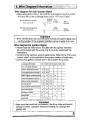
Basic PC Operation
This system will basically operate the same as any other Windows®
based software, such as changing windo'Nsize, closing wir,dow, mouse
operation, quitting, and etc, For further information, please refer to the
"Getting Started" manual included with the Windows® Software.
Please Note
• The Support Tool v1.10 software has a Main Unit (a-Manage)
Update v1.20 program that will automatically detect and update an
old version unit when the Main Unit is linked with the PC.
6
.-
=
Follow the instructions listed below to install the Support Toot software.
Software Installation
1. Tum Personal Computer "ON"
2. Insert the Support Tool CD-ROM in the CD-ROM drive. This
software is a self installing software, so installation will begin
soon as the CD-ROM is inserted. Follow the instruction on
the screen.
3. Afte( the installation is complete, GReddy e-Manage
short cut icon will appear on the desktop.
p
iJ"
:"jiFll?i02;
: "·[J)ilM.9.\'! i
l~"~~~!l
Important
• If the self installation fails
Depending on the computer's settings, it wUl not allow self
installation. Vvhen this happens, double ctick the "setup,exe"
in the "DISK1" folder in the CD-ROM to instaH the software .
• If the program does not operate properly
Un install the program, and reinstall the program;
• If communication feature does not operate
Uninstall the program, and reinstall the program.
To uninstall
1. Click on the "ADD/REMOVE PROGRAM" in the "CONTROL
PANEL".
2. From "ADO/REMOVE PROGRAM" list, select "GRaddy e-Manage
Support Tool", then click on "ADD I REMOVE" button.
3. Click "OK"
4. W1en It return to the "ADD/REMQVE PROGRAM" window click
"OK" to go back to "CONTR()L PANEL".
5. Close the "CONTROL PANEL" window.
7
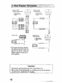
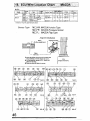
Wire diagram for Injector Signal
• Please read the instructions included with the Injector Harness kit,
and proceed wittl the wiring only if you fully understand the
instructions.
• Connect to the 'Jehrcle's Injector signal wires. Refer to the 'Vehicle
Specific ECU wire location chart" at the end of this manual for the
proper location pf each wire. Make sure that you connect same
number of wires as the engine's cylinder number. (Excludes Rotary
engines)
• For Rotary engines, you can only wire the primary or secondary
injector signal or both.
El<""'IIo I f« BNRJ2
!Ox~I.
2 HI JZXW
(6 cy\'IlClOl' ...gIno wM
Q M.l!O c»M".:I"f
a F""Ole CMneclOl
~
31njOCIo< Slg/lalwitQj
8pJ1w
{5 C)'lnOer et1~ wIlt.
:3 injector SIglr;JI .....itoj
PIR • Pu(p/elRoo
pvn - PI!i.lriRea
Important
• If the vehicle does not have the same number of injector signal wire
as the number o! the engine's cylinder number, group 2 wires in to
one. See the diagram above.
8
1~~t;W~r!lJ~ll~Q~~;~~t9,®~~R"ii;;(:jr,!iitn&j};\t~;;:~n:};:~?;;i,; . '.;:.~';'
Wire diagram for Sub Injector Signal
• Vllhen using the IfJ CH-A. IIJ CH-8 for sub injectors, set the jumper
JP5 and JP6 in the e-manage main unit to "1-2" from "Open".
(For low resi.stance injeC10rs)
VJ CH-A or CH'B"--'
Fuse
(for high resO$ta."')cs Inje<;(Qrs)
UJ CH·A or CH·B---··,,·,
Ba~elY
(S-10A)
''\:j.: " ... --.-.~~----. + terminal
~
:t
Important
• If the vehicle does not have the same number of injector signal wire
as the number of the engine's cylinders, group 2 wires in to one.
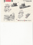
Wire diagram for Ignition Signal
• Please read the instructions included with the Ignition Harness
Kit, and proceed with the wiring only if you fully understand the
instructions.
• Connect to the vehicle's ignition signal wires_ Refer to the "ECU wire
location chart" in this manual for the proper location of each wirE;! .
.. Gonn~ct the ignition channel wire in the engine's firing order.
-
,.-
e-manag8 IJU Channel
CH-l
r-----...
:i; 4, 6, 8 cylinder di$iributor
t
-
lnllne 4 cylInder grQ~p ignition
'KOfI~ontany
,
-.
•.
t1 i
t3
t2
l4
! ·tlf~" tZ,5
..
-.~
---_.-
t3a(FC3S, JC3SE)
208 (-IeESE)
.--_ ..._---.
.-,
,-
t5,2 t3,4
i
t$,6
~
Inlina 6 c)'lind!)r individual ignilion
V6 Individualignilioo
f-,-.
t2
,
t5
t1
._---t1
12
tT
tL
f
t3
...
IT
113B (F~3S)
t3
"
..-
q+6
.~~.
I
I t1,6
Inline 6 ~yfinder gl'Oupignllion
-t4
HOfizontaAy opposed 4 cyllndef
;-.
~31~ f-".CH-5
t3
11
---.-
12,3
tl,2 t 13,4
lnllne 4'o~lnde, individual IgnlUon
VG "roup Ignition
-
t1,4
opposed 4 cylinder
..
Oi-Z
.
j---
,,--~
-.~t:-l- t~
.
tL
!
-
t
.".- .•
_-
Important
• Make sure that wires are connected in the firing order and jumper
setting is correct. Improper wiring and setting can damage the
ignition coil.
9
E.''''''~ 1: 1lNR32
(Ilihfie 6cyL Irl~'oIldua.l i[j.'"IiliOn)
~
.'---;:;:'-j- ,,
~
;~enb:tl14 Go"II/~ lI(\1t~
MaiO C(l1n~clC(
~.am~o 2: N.N)CF.
(.<I<.'jl. gtouPX~I'Jt'Cf;j
~ M(I(C 1;¢nIKt~~:f;(
!
:) f ef)ltlJe ~.clrte(;t(,lt'
f- Spfice
~ F~ma.h~ ~(.ltlrl~£1Or
, Srjjc-e
Example 2:.AEI11
(DISliIIlU"" I91I~on)
~
Malo roMeo",r
~
S¢<:o
n Filmalo crnooc1tr
* On Honda EG type vehicles,
the bottom third pin from the
right on the 26 pin is also an
ignition signal. Group the 2
wire together.
Important
• On Honda, set the jumper pins JP 1 and JP2 to 2-3 .
• After wiring, if the tachometer, or not firing occurs. set the jumper
pin JP2 to 2-3. (especially on Toyotas}
10
~-
._,
- ...
.--
-~----.
1.•
~f.~i~~~~!;iYPi!';R!9.!..I"!;;t;':,';,:MS,";"";~;K;·l'·.;;;?~!/':.:':}i%'<·'i"'~!,:;:::{'; . .• ]
Starting the application
1. With the IG key in "OFF" position, connect the the PC, and
a-Manage using the Communication Cable. O-Sub 9pin connector to
PC and U S8 to the e-Manage.
2. Turn the lG key to the "ON' position, then double click on
the e-Manage short cut icon on the desktop,
3. VV'hen Iheapplication opens, you see the following.
,
I
.1
it ,
."(£Y
'-
.rqki) itel:lSYI'
.Gflcddy ",mao"go support TOOl Stoge 1
Please
• Use only the provided communication cable. If a different cable is
used, it might damage the PC orland the €-Manage.
Download the communication Program (Main Unit Update)
1, Always disconnect the 12 pin connector On the main unit.
2, Check and make sure thai th.e sta.tuS.bar is d.iSPlaying "ONLINE", If it
does not .shOw ·ONLlNE", Check the COM port setting,
.
,
.. .
,
"-;,",
..
" " . '
,
,
..
',"
11
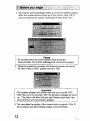
3. The program will automatically detect a unit will old system program,
'Mlen the update window shows up on the screen" click ·OK" to
start downloading the update, Download will take about 2 min.
Please
• Do not ,disconnect the communication cable during the
communication. PC and the e-Manage will not function properly.
4.VlJhen the updating is complete, the following window will pop up.
Tum the IG key to 'OFF" position and click "OK".
Important
• The updated program wil! confirm once the unit is turned "OFF" .
• When the unit is turned back "ON", the following message will come
up. "The data in the Main Unit was losH Please export data." this
shows that the unit was properly updated.
5. This comp!etestM update of the commurtication program, If the 12
pin connector was disconnected, please reconnect it back.
12
n:m~
Main Unit Setting Information Confirmation
;,:...;:V;>',,;;;';
1. Tum the IG key to "ON" position and check to make sure tilat the
status bar is displaying "ONLINE". If it does not show "ONLINE»,
Check the COM port selting.
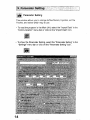
2. To confirm the Main Unit Setting Information, select the "Main Unit
Setting Information" in the "Setting" or click on the "Main Unit Setting
Information" icon.
"Changes can not be made in this window.
• For the Rotary switches 1-3 setting information please refer to the
e-Manage manual.
• For the Ignitiordgnition Input Jumper Setting, refer to the "VVire
diagram for Ignition Harness" on page _ '
• Air Flow Meter 1 - - - - - - --Used for Hot wire, flap type airflow
meters, or MAP sensors
• Air Flow Meter 2 - - - - - - - -Used for GTR(Skyline), or VTEC
• Airflow Meier Pulse Input- - -Used for Karman type airflow meters
orVTEC
• Airflow Meter Purse Qutput - USEld for Karman type airflow meters
orVTEC
• AAV Value - - - - - -- - - - -
Displays the. Main Unit's MV seWngs.
13
:::?;:! _~!~~~X:-!
[~:: Parameter Setting
~::~:",,:!I
This window allows you to change Airflow Meters, Injectors, set the
Throttle, and select which map to use .
• To read the program in the Main Unit, select the "Import Data" in the
"Communicatiorl' menu bar or click on the "Import Data" icon .
• To show the Parameter Setting, select the "Parameter Settjng" in the
·Settings" menu bar or click on the 'Parametersettirig" leon.
14
~~:\e~,t~m~J~!;$~!1iJ}tI.s;fiX;'I;%j;jk<i~r~iwr~~;'{;,E;;,:{i!;"W{':1.,;,,,;,<'\,':;]i'·,;
Parameter Setting
Air Flow Meter Change
• \J\Ihen the Airflow meter or MAP sensor is upgraded, cheCk the
Sensor Type from the "Vehicle Specific ECU wire location chart",
and select it from the pull down menu,
• The Airflow Type programmed with the Main unit's rotary switch will
display as "Main Unit Setting" in the pun down menu,
.. \J\Ihen the airflow meteris
upgraded, the airflow signal value
will change, Make sure to check
Air/Fuel Ratio with a.proper
equipment to ensure proper fuel
mixture.
GRtddy Pressure Sensor
• Choose this box when an optional GReddy pressure sensor will be
used for the scale of each Map tables.
+ This function is used wheh the system exceeds the Air Flow Meter's
capacity, The factory EeU will continue to read off the Air Flow
Meter, but the a-Manage system will work off the GRaddy pressure
sensor.
• In the Sub Injector Map, the injectors can be controlled by rpm
and the GReddy pressure sensor signal.
Absolute Pressure Sensor Change
• This function is used when thasystem exceeds the factory MAP
Sensor capacity. The factory EGU will continue to read off the
factory MAP sensor,but the e-Manage.system will use the
calculated absolute pressure from the factory and GReddy pressure
sensor
.. Use Absolute Pr(3ssllre Sensor when setting the vacuum as "0'
value.
* Use Relative Pressure Sensor when setting atmospheric pressure
as "0· value,
15
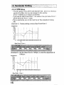
A.A.V. RPM Setup
• The rpm points of the AIR FLOW ADJUST VOL. (A.AV) on the front
panel of the Main Unit can be changed in this window
(From O·10000rprn in 100rpm increments)
• If you set the start Point;::Point 1, the value in the rpm below Point 1
will be set to the Point 1 value.
-This is used when you do not need the air flow adjustment during
Idle.
(Example 1) Factory .setting is set to Start Point=Point 1
Adjustment
+20
i
-i,
+15
!
. i
+10
+ 5
i
!
• 5
-10
-15
1---+--"-
o
-20
.,.
.
\
o
f . ...
.,
.
1 000 lOOO 30004000 5000 6000 70008000 rpm
Start point"" Point 1
(Example 2) Set the Start Point to 1000rpm, to start the adjustment at
1000rpm.
Adjustment
+20
i
+15
:1~«_~-I
o
~~~+-
__~~_~i__+I__+--1
~1~:
1
:
·15
'1
-2Q
o
i
i
1000 2000300040005000600070008000 rpm
i t
·Start Point Point 1
16
I !
Injector Change
• When upgrading the injectors, this feature calculates ti.e difference of
the two sizes and trims the whole fuel map (factory map) for proper
idling and drivability.
• Input the factory injector size and the upgrade injector size.
• This system can control up to 150% larger injectors than the factory.
Too large oran injectors can cause problems performing properly.
.,. Wlen the injectors are upgraded, the injectorsignai value is being
altered. Make sure to check the Air/Fuel Ratio with a proper
equipment to ensure proper fuel mixture
Map Select
• Place check marks on the features you need to program.
* On certain applications, you will need to Select the proper engine
type from the Engine Model pull down menu next to the Additional
Injection Map. This sets the system up for the proper numbers of
cylinders, and sensors being used. If it is does not allow you to
make a selection, skip this step. This means that the system already
has the proper setting.
17
Throttle Setting
• Click on the "Throttle Setting" button on the bottom left corner, to
calibrate the throttle position signal. Follow the procedure on the
screen,
* If the Throttle Setting is not properly programmed, the Anti Engine
Stall and Air Flow Adjustment Map will not function properly.
* \M'lenperforming the Throttle Setting, make sure that the IG key is
tumed to the "ON" position. (engine should be "OFF")
• After the Throttle Settirg is complete, confirm that wide open throttle
shows 100% and fully closed shows 0%. If not perform the setting
again, orchael< the throttle signal wire.
Important
• On the vehicle without throttle position sensor, or with only a throttle
SWitch wilf not be able to set this aod the related feature.
Confirm settings
Once aU of the settings in the Parameter Setting is complete, click on
"Confirm" to send the data to the Main Unit. Then tum the IG key to
"OFF" position.
18
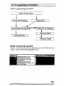
Basic Programming procedure
L_~_S_t_art_A.!..-'pp,----l_ica_t_io_n~-.--_.l
I
Program Setting
Input Data (revise)
Real Time Display!
Dave to File
Analyze Data
Setting and Opening map table
• Open te desired map tables by selecting from the MAP SELECT pull
down nenu or click on the appropriate Icons:
19
"
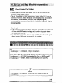
Inputting values
• To input a value in a desired cell, click on the cell to high light it, then
input a numerical value.
• To input the same value into a whole column(s) or row(s), click on the
blue axis cel! to high light the entire the column(s) or row(s).
• To input a value into a block of cells, high light the desired block of
cells.
o By using "pg up" key, you can increase tile input value in the selected
cells.
• By using 'pg dn" key, you can decrease the input value in the
selected cells.
• Use the "undo" in the "Edirpull down menu or icon to cancel the last
change.
• If a improper value such as too large of a value was inputted, error
message or the.closest value will be inputted.
ItI
Interpolate
• Use the "Interpolate" button to fill in the values between two ceils, or
four cells in the corners ofa block.
Initial Programming (Map Clear)
• Select create new file from the menu and export it to the Main
Unit. This will dear any program in the e-Manage. This cannot
change the switch setting on the e~Manage.
t' •
~
TobIt~I
• This featUre. can be u.sed when the Main Unit is used on a different
vehicle.
20
1'5!1,1:;:·;~!.tS~~4~tf.~AM~~t:Yi!:n~:q~)Jnfp,t~~t~9Q,.t~);:·},],;!'f':':1
S:e1
,.-.-.- .. ,-..""'''''.... -~
Boost Limiter Cut Setting
• This is used to eliminate the factory fuel cut by ECU due to the
increase of the intake airflow.
• The Air Flow Meter or MAP sensor input signal to the ECU can be
clamped. However, since ECU can not recognize the amount of
increase of the intake airflow over the clamped signal,
compensation (increased fuel) in the Additional Injector Map is
recommended.
(To set up)
1. In the data 1099in9 feature (Data Analysis), record the rpm point and
air flow meter/MAP sensor voltage and. injector duty cycle where
the boost limit occurred.
2. Input the clamping value. Input a value slightly lower than the point
.where injector duty cycle becomes 0% in the data.
rpm:
Input range: 0 - 10000rpm, 100rpm increments
Cramp Value: This will automatically change according to the sensor type.
Input range: a - Sv, a.05V increments (Air Flow, or MAPtype:V)
Input range: 0 -3150Hz, 50Hz increments (Karman type :Hz)
• This feature is not used for the vehicles that does not have a
boost limiter.
21
1.··••
'.1~~}~~~~.p;'tla·;·~p;·Wh1dq'i! . lgf.c:)'Mii,.JQrj';~¥'!D:.~>f;l
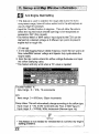
,E,S! Anti Engine Stall Setting
"', ,.,:., , •• ..:.'...: :!.
• This feature is used to stabilize the rough idle due to the turbo
compressor surge, blow-off valve vented out to the atmosphere or
use of a high lift camshaft,
• Input the Throttle Position in degrees. This wit! allow the va1ues
below the inputted value (throttle opening) to be recognized as
accelerator OFF (fully closed).
• The Airflow Meter or MAP sensor input signal to the ECU can be
clamped at a desired voltage at 8 different rpm points to prevent
engine staH or rough idle,
(To set up)
1. In the data logging feature (Data Analysis), recOrd the rpm point, air
flow meter/MAP sensor voltage and jnj~or duty cycle where the
engine stalls.
2, Input the rpm points where the airflow voltage fluctuates and input
the airflow clamping value .
... This feature will onlyworkwhen a T.P. value is inputted,
Throttle Position: %
Input range: 0 - 10%, 1% increments
rpm:
Input range: 0 - 8000rpm, 50rpm increments
Clamp Varue: This will automatically change according to the airflow type.
Input range: 0 - 5V. a.05V increments (Air Flow, or MAP type:V)
Input range; 0 - 3150Hz, 50Hz increments (Karman type :Hz)
• This feature is not needed for vehicles that do not have any engine
stalling problems.
.
22
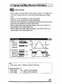
• This is LJsed to set the VTEC setting without going in to the Main Unit.
• The VTEC setting 'Nith the PC will over ride the setting on th Main
Unit.
• VTEC Lo·>Hi is the shift point under acceleration.
• VTEC Hi->Lo Is the shift point under deceleration.
• VlJhenthe VTEC shift point is changed from f~ctory setting, the airflow
will need to be adjusted for proper air/fuel ratio.
• VIlhan a shift point IS set lower than factory, use ECU-Lo E/G-Hi to
compensate for the Airflow difference.
• VIlhan a shift point is set higher than factory, use ECU·Hi ElG-Lo to
compensate for the Airflow difference.
1!I~f.3
"'vrf/: SET rING
Shift Point
VtECt(hHI·
~celerationJ
RPM
(lpm)!JO inctemet1t
lO.>HI t - - - V
.
VlECHI'~LO
. f[)~alIQn)
~I
48001
i..-..:...----~~TlME
Ail FIowA~nWt
ECU-l.O EXl·HI
{Shit Point <OligiM/ Srit
ECU·Hf EItHO .
(Sh~ Point)
RPM
6\
Original ShWI Point)
rpm:
Input range: 1500 - 7000rpm, 50rpm increments
Adjustment Value: %
Inputrange
: -20 - +20%, 1% increments
Input range
: 0 - 100%, 0.5% increments
23
1··1J~·;~~5ije.;;a't,l(J.[:J\I1~p,'i!hl~qW\I'~f<.i~,~'i~,dt~ii,/m:;};;:.,;. j
About scale in Map
Air Flow Adjustment Map
Additional Injection Map
Ignitron Timing Adjustment MAP
Sub-Injector MAP
• The value in the scale can be changed, by licking the "Scale Change"
button and inputting a value. After the change is made, click on the
".Scale Change" to lock the value.
• Since this is a "piggy back" system, a "zero" value inputted in any map
table will be Same as the factory ECU setting, and any value other than
"zero" is the adjustment to the factory ECU signals or program.
RPM axis:rpm
Input range: 0 - 1QOOOrpm, 100rpm increments
Load axis: V, Hz, Absolute Pressure (kPa, kg/cm2 ,mmHg),
Relative Pressure (kPa, kg/cm 2 ,mmHg)
Units will automatically change. accotdinglothe airflow type.
Input range: a - 5V, O.05V in¢rements (Air Flow. or MAP type:V)
Input range: 0 - 3150Hz, SOHz increments (Karman type :Hz)
Input range: 0 - 5V, O.05V increments (GRaddy Pressure sensor:V)
Please
• The pressure (kPa) displayed in the load axis scale is converted
from the sensors voltage value, and kg/cm 2 and mmHg display is
converted from kPa. When the scale is changed, the system will
round off the last digit duririg the conversion, so to make the proper
change, perform the scale change in the voltage scale.
24
"
g
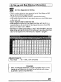
Air Flow Adjustment Setting
~t .,_..>':,~,:... ".;
• This is used to adjust the input signal of the Air Flow Meter or MAP
Sensor to the ECU for fuel enrichment.
• 16 points of rpm and throttle position is used for fine tuning.
• This settirtg will add to the Air-Flow Adjust Volume (AA.V) RPM Setup
on the main unit.
• Inputa negative value to take away fuel.
• \Nhen programming the Air Flow Adjustment Map with the PC, it is
recommended to set all of the Air Flow Adjust Volume (A A. V) RPM
Setup on the Main Unit to "ZERO".
• Since this is a "piggy back" system, a "zerd' value inputted in any map
table will be same as the factory ECU setting, and any value other than
"zero" istha adjustment to the factory ECU signals or program.
Adjustment Value: %
Input range
: -50 - +50%, 0.5% increments
Important
• When a substantial adjustment is made, the ignition timing can be
change as well. Make sure to cheCk the airlfuel ratio with prop",r
equipment to prevent any detonation.
=
25
1:~".~:j~~~~,~P;'~~c;I'M~'~':W'n~9W;IQ~rm~~,iqrJ"'!;D;>\ •. • 'i:,1
,liiUl
.-'
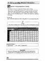
Additional Injection Setting
t.: '. ..;
• This is used to increase the factory injector's fuel injection by adding
to the factory programmeo injector duty cycle.
This feature is required if Boost limiter Cut feature is used.
• The additional range is 0-100%. However, t.he duty cycle of the
injector cannot exceed 100%.
• Since this is a "piggy back" system, a "0" value inputted in any map
table will be same as the factory ECU setting, and any value other
than "zero" is the adjustment to the factory EGU signals or program.
v
(Example)
If factory EGU injector duty cycle is 50%, and 30% was inputted in
this Additional Injection Map,
50 + (50 x 0.3) = 65%
(TO set up)
Input a desired increase rate of fhe factory duty cycle in the
corresponding cells.
Adjustment Value: %
Input range
; 0 ~ +100%, 0.5% increments
Please
• To take out fuel, make the adjustment in the Air Flow Adjustment
Map.
26
;j~;1''';Z$fJt*qp.,~q~[;~~piWipa~~':Ui~(ftm~,j'~ijh''·,5;'r (:v" '.
•
Sub Injector Setting
:!.::::~.;.;~~'
• This feature can be used if the application requires more fuel (han the
main injectors can provide.
• This feature will drive additional sub-injectors once every two rpm
signal pulse. (For 4 cyL, twice every two rev, and for 6cyl., three
times every two rev.)
• Either injector duty cycle or duration can be select~d as the numerical
value in Map table.
• The injector cjuty cycle range is 0-100%
• A value higher than 95% entered will be displayed in RED.
(To set up)
Input a desired duty cycle or duration in the corresponding cells.
Adjustment Value: %
Input range
: 0 ~ +100%, 0.5% Increments
27
~~ Ignition Timing Adjustment Setting
'~~'--.('
• This allows the tuner to adjust the factory ignition timing.
• Since this is a "piggy back" system, a "0" value inputted in any map
table will be same as the factory Eel! setting, and any value other
than "zero" is the adjustment to the factory ECU signals or program.
• Input a number for advancing and "Y before the number for retarding
the timing,
(To setup)
Input a desired adjustment rate (in degrees) in the corresponding celts .
• The value inputted in this map table is not the actual ignition timing.
Adjustment Value: 0
Input range
; -20 .. +20°, 1" increments
Important
• Since the e.Manage does not receive the crank angle sensor
signal, there is a possibility that the timing could be off by ±1D.
28
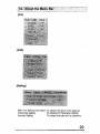
j.;i~~p:i~t£~tu':1he.:rM'lj).i.!f3.a r;i:i~i\.•,::iX;';a~~'···:U;{~;:(··. ····,':';·i.\
[File]
[Edit]
[Setting]
Main Unit Setting Information To display the Main Unit's Settings
To display the Parameter Setting
Parameter Setting
Security Settfng
To protect the data with a password.
29
-
I
:t~;~~3;'A",~,~!:'1f,ttf.kM~ ij~;'~~!,J:~t)W!';;t;ri.;':':Yf'};,J,:t'iM;;,/1~,~';Wf5S;t,j;:;;,'.
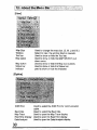
[View]
Map Size
Window
Toofbar
Map setect
Map button
Status bar
Indicator
Used to change the map size, (S, M, L and XL)
Select to view the window tiled or cascade,
Used to show or hide the Tool bar.
Used to show or hide the MAP SELECT pull
down menu.
Used to show or hi<;!e the Map icon buttons.
Used to show or hide the Status bar,
used to show or hide the Indicator.
[Option]
Used to selecUhe COM Port for communication
cable.
Baud rate
Used to select the Baud rate.
Used
to open the Map Trace display,
Map Trace
Real Time Display Used to open the Real Time display.
Data Analysis
Used to open the Data Analysis display.
COM Port
30
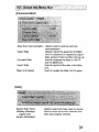
[Communication]
Real lime Communication Used to start or end the real time
communication.
Import Data
Used to import the data from the Main
Unit. If a password is required to import
data, password inputwindow will pop up.
Compare Data
Used to compare the data on the PC
and the MaiN Unit.
Export Data
Used to export al! the data to the Main
Unit.
Main Unit Update
Used to Update the Main Unit Program.
[Help}
Search Help Topics
Used to search the help menu by topics.
GReddy a-Manage
Used to show the current software and
support tool
main unit program versions.
Version Information
31
Tool Bar
Menu
1. New file
2. Open
3. Save
4. Print
Edit - - - - - - - - - - - - - - - - - - - Page
S.Cut
--
6. Copy
7. Paste
8. Undo
9. Redo
10. Interpolate - - - -
4
-
-
-
-
-
-
-
-
-
Page _ _
Setting - - - - - - - - - - - - - - - - - - Page _ _
11. Parameter SeHing - - - - - - - - - - - Page _ _
1:2. Main Unit Setting Information
Option - - - - - - - - - - 13. Map Trace Setting - 14. Real lime Display - - - 15. Data Analysis - - - - - Communication- - - - - - - 16. Import Data
17. Compare Data
18. Export Data
- - - - - - - Page _ _
- - - - - - - Page _ __
- - - - - Page _ _
- - - - - - - Page _ _
- - - - - - - Page _ __
- - - - - - - Page _ __
A bout the Indicator
• The e-Manage mark on the top right of screen is a communication
status indicator.
OFF LINE - - - - - - - - - - - - Yellow (solid)
.' ON LINE - - - - - - - - - - - - - Green (solid)
ON LINE Real Time Communication - - - Green (flash}
ON LINE Recording Data - - - - - - - Red (solid)
32
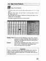
MJi~
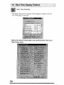
Map Trace Feature
• This allows the tuner to pin point the current location on 16 x 16 nap
table.
• Select the "Map Trace" from lhe i'Option" in the menu bar or click on
the "Map Trace" icon.
o Once the Map Trace display is opened, the tracing will begin in the
opened 16 x 16 map tables.
o
This feature requires Real Time Communication.
Display Time: The trace can be delayed by 1 sec, 3 sec, 10 sec or
continuous for easy monitoring. W11en continuation is
selected, it will display the trace path (trail) until the
Cursor:
"clear path" is used.
There ate two selectable cursor sizes. (ibox or 4 box)
W11en "4 box· is selected the surrounding cell of
the current value will be hlgh lighted
Important
• There is a possibility that the map trace wilt delay due to the PC's
RAM size when multiple map table is opened and/or Real Ttme
display is being used at the same time. In this case, open only one
map table at a. time.
33
liIIHI,
Real Time Display
• This alJows the tuner to monitor all the signals coming in and out
frQm e-MallClge in real lime.
• Select the desired input data to be monitored from the Input
Data Setup menu.
34
.,
'
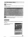
Graph Display
•
•
•
•
Click on the "Graph" bctton to display the graph,
Click on the "Reset" button to clear the graph,
Double click on input data to adjust max.and min. of each scale,
Double dick on the color box to change the line color.
• By pressing "RECORD" the selected Input data will begin to record.
• The recorded data can be saved on disk.
35
Record Data
• Stop Button:
Click onlhis button to stop recording,
Save Data Button:
The recorded data can be saved on disk,
• The recorded and saved data can be opened in the Data Analysis
Feature.
36'
; i~1f~i.~~~
~ "'>~',/':':
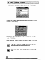
Data Analysis
• This allows the tuner to monitor all the signals coming in and out from
e-Manage in real time,
Open File button: Click on this button to open the saved file
Real Time Monitor Feature
• Select thedesjred input data to be monitored fram the Input Data
Setup menu,
• Double click on the color box to
change the line color,
37
• Double click on input data to adjust max. and min. of each scale .
• Oouble click on each measurement to view the max. and min. values
recorded in each category.
• Click to high light each of the input data in the table too show the
scale of each data.
• Usingfhe mouse, click on graph to see the input values at that point.
• High light a section on the graph and cHck on the" zoom"
button to zoom in to the selected sections .
• Click on the "Back" button to return to the previous graph
sIze.
38
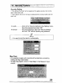
Security Setting
• This allows the tuner set up password to apply security lock to the
dat8 in the main unit.
• It will require the tuner to input a password to communicate with the
main unit..
To LocK - - - - -Click on the "Security Setting' in the "Setting" menu.
Input the password and click "OK".
To Unlock - - - - Input the password. Open the "Security Setting"
and click "OK" without inputting any password.
• It is used to lock the data for confidentiality.
Map Clear
• It is possible to erase and overwrite all the data that is locked by
clicking the Map Clear button.
• To Clear the program, click on "Clear Map" in the Password input
window.
39
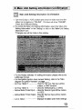
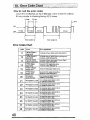
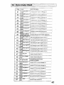
How to read the error codes
Count the red flashes on the e-Manage unit to check the code(s).
It's very similar to checking factory ECU codes.
Error rode {131
Error Codes Chart
CooE
Error
AirflOW Signal 1
Input error
NrfICM' Signal 2
input error
11
12
Karman VortP.lf
13
14
15
i
sensor input !lrror
V1'EC Signal
input error
Alfflow v(1taga
<J\J!puI
error
In~OIt<iclwirl''ll1Jl
dlsoon.\<lctad},ldlaN $ignl11
Irtc<l<\'1)l;! wiring Qf<.li5QQn(,w",j Ahllt'JIISlgnal 2.
Inrorrect JUmpat' set11"91""3).
h>co<rect wiling or <Ii$'<X)l'lnoo"d K."""" Si9'IaI.
InCO!J'!ld JlJrtlperse!!lng (.f'4),
InCQfl'tld VII,C 9g<10linpul .. long.
. Incooect Jump""~!t>g (..f'4),
lncOOect ".ltnow Sill'1al ootput wltir,g
i6
VTECSignal
IMMed VlEC 9{111af ouipUlwi<1n9·
<)IJlput E!l1'or
JncOlToo Jqmper SEllflng <.1'3).
20
No Injector
NoI,oe"",lng M InjlXlQ' sI\1mf fer
pulse from a~
21
No Injector 1 pulse
Amon'" Inje<;tkm Map
Not wclliYlng tnjoctcr 9Qrl3! IfJ CH-l
22
Not recmrlng Inloolor $I9nl)l IIJ CH·2
No frljector 2pIlIse IrA AddJllO'llillnjedion M~p
23
No Ifljedor3 pulse Not r<><=eif1ng Injilctor $lgntllllJ CH-3
24
roollvlng injOOlor slgnall/J CH-4
No fni ector 4 pulse Net
(0/ AdtSo1iooallnfllcllGn Map
25
Net rGl;:!llving injector sI~nR! UJ CH·5
No Injector 5 pulse rill'
IIddMnallnjedlOl1 Mnp
26
Nct (OO<lMng injector slgnlll qJ CHoil
No Injector 6 pulse 1«
AddliOOallnjoctlO<\ Map
27
28
No InJoctor A pulse 1« A<!<;IilionaJ Inj1lt:t1on Map
Not rocoivll1g iniocto< signal YJ CH-8
No Injector 8 pulse
"-'~''''''''''''
40
Error dBScrlptton
1(>1' A!I<!Itloool JnjOO1\Qj\ M~p
ret AddJtlOl'lllllOjedlOn MUll
N¢I rocolvlng it'ljoctOf signal YJ CH·/\
1000Ai.kW0Il/l11njOCliOn Map
...........
,~'v_.
CODE
t: rtO(
Error descnplfon
1-----+-,----.. . . , - - : - - [ - - - - - - - - - - - . - - .
31
lriCQrred
~nfed(:t'
"
Incorrect UJCH·l
'."w':!t0~~Mat1avc Ullil
~__--~PU~i~~~~~~~~t_------__------~----.~-----32 lncorrcct 1uieccr 2 Incc;re.:1 jjJ Ch 2 I\!!r£! to e·Mttnat.~J un!!
---~~-----..,:-l--.---------~------..-l }neared lfljedrf 3
lncomxt V.I CH.3 Wir?loe-M~naf,1(! utl~
33 l!~-___.__+j __----------_--_--,
--
tlCOlHirt lnjeclcr 4
34
pulse
35
pul~
Incorred Inlectoc 5
Incorrec: V,j CH.-\ WJ(O te a-Manage ur,j!
InOO'rod tlJCI;1-6 .....!II to e-Maollg<) una
~--
lnClXl'tld IIJ CH·n ""'a 10 e·M""\<J'''ltl~
37
Incoaect lnje(la- B
38 I pulse
ImprQPer otder ot
40 IgnitiOO Input slgnal
41
42
43
44
Intolrod II.! CH.B wire 10
.,-M,,,,BgU unit
No ltP\ioo Signal 1
i pulse
No Igrdtioo Signa/2
pulse
No! rOO>lvil1!llhe 1.'1.11/0<> ~allo It> CH-2
No IgnitlCKI Signal 3
Ipulsa
No IgnlifOfl Signal 4
pvlsa
No 19OOioo Signal 5
I pulse
46
No Igniti()'l Signal 6
'---.:.:=-~pp:~\If~a8~_:_:_:::_-+-~---_------.-..- - -
47
48
..PI PULL UP
erroc
.P t PULL DOWN
erroc
In=roctJumpff$f~It"g(Jr>l)
No IgniUOI1 pOise
Nr.l receivirlj;t 1M ign«im "\jIm!
ticooed Ignition 1
pulse
Incam:d IOCH·IIIII'e!" 6·Manago un~
In~{ecl IijrrrtiOl1 2
Incorred 1C'l CH·2
Im:CHed Ignitlon 3
I"COf~ ICiCr!.:;WitOtocrM""oo<iun~
l-..:4..:.:9:...+__-=--:-:-:::__-:;-!-=Io~an::.!Y:..:or~t:::."E>=-<tI~Ilf--':.:....s----_:_---~.
51
52
pulse
53
pulse
54
Incortect ignition 4
pulsa
56
57
Wi,,, l(l"'~-"Ilage llllij
Incorrect ti) CH.4 w"u 10 ,,·!,I>lIl1l9" ~Il~
lI1wred IgflitiOl1 6
IncorrQd IOCH·6 Wi(o 1<) e·M"/l~QI) un~
.P2 .. 12V
)Ilr.(lCI'6(lJ.Jmper sdtJhg (JP2)
p(.llse
:
~~e~~--L-------~--41
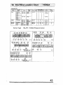
Sensor Type
<I-
t\:
TY_HW TOYOTA Hotwire Type
TY_PR: TOYOTA Prei$sure Sensor
TYJL: TOYOTA Flap Type
+- Pew er
" .£' +-Oro\Ind
: I ' -RPM Signal
nl'! ....fhrottl$ Signal
N:.
...ND.lIIlnj0d.ct SI\lflal
... NO. Ii tgMloo SlQnat
1: t: ... R"M I'. 19nklon Sign'"
,~iE~' ·NO.• &No. lIfllJllitiO!lSigoal
..
'Ii: ',:
"'l~"g 19ot\on Si9nal
,yr.'
+-Airlk;wlPreswN)!SigIaJ
... VTECSl!Jnal
jtffi:'
+- NO.• Tlililln\llgn~1Cri
,~,
... vrMSp
)ft~:
... NO. 1Il1'1ImiJIY lnj0dorSI(;l1a1
,iii( .... tn/lldor Oro\md
42
#"!t.
;i~;
Slg!ll1!
,~~: .... NO. li( Sooon<iM' InjOClQt Signal
HONDAJACVAA
Ch~ •
'i~Ioikt::,~ 'C<id<i
.
.
."
, '
EJ6
IBf-'-.f.Ja81
~3 _ _
rrtl
816A
} Hl'L
96 ~- CD
016Y
,
99 -
92- 95
iI
I
I
i
,;
D16l
:
~l."
i
EGg
De2/DBI!
Integra
Pteluae
BB6/Bsa
Acc-ord
CF4
Si:lL ..
...
'ri~
; c:
~
l'MIJ.~
C~vic
,/.
f!l)g/f!j>' .
.ear ., '.Coda:,'
•.
• V
,',
I
00 - Ot
94-96
97 -01
197,~"';
IsS.S
Sensor Type
97,S
HNj>
BI8C
B18C(MlTY
HZ2A
HN:::-'
FZOB
HN.P
- f~ --_..
HN_PR: HONDA Pressure Sensor
r
I
.
,-
,i
H-l
j -".-- ...
.. - ..-.-.......
*- Vehid" wilh
H -3
VlM signo. QO(Y'
{iM'
, ....
~
'-,'-
..............
_--- .. _----_._.,----
"-'--"
H-4
43
"it
Sensor Type
NS_HW: NISSAN Hotwire Type
N-3
N-l08 .
44
=
MITSUBISHI
Sensor Type
M'CKR: MITSUBISHi Karman Vortex Type
,.
'+8' '-PO'I'IOI
,J,
--Ground
<-RPM Signal
...Th,aulG Signal
J .'
'1~.
J.,r 4---Ajrfl",,,,lPfIol1:WIO ~aI
..Y.! -IIT'EC SigIlr<l
.;yy,
...vrM Si;Jna!
,lie;
~lnjOdQl' ('''QUod
,. NO.)I( InjoctlX S'!JfIai
~!I(' •• NO.• IlJC!iioo Signal
t',f ... RPM 8. IgnkiQll Si;Jflal
·.tJ,(;'1O( <---NO.• &NO.lI!JO"k'()I1 Si!)<lW
.11""
·Il
.-laaditll.l tonkion S~ ~
ttil!
.- NO. AI Itlldillg tgnniQn Sigani
f~'" ,- NO. Jf Primary InjedIX Si(l!lal
.~,~~ .' NO. ~ SOOOI\<1ery Injoc!<;< S,rylal
45
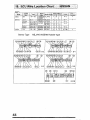
"'A~OA
Sensor Type
MZ_HW: MAZDA Hotwire Type
MZ~PR; MAZDA Pressure Sensor
MZJL: MAZDA Flap Type
Adapter Installation
Sl1pplied resiste<
White
(Airflow signal input)
.---++++++t-!
~~
• []]J
*
,,,
L - (Ground)
81ad< _ _ _ _ _--l
<D Plnoo !'",Air.ow sign'" input 'lJr~ (Wllte) and
"",,/Od (Black) in 10 the 'OOp!1If
® Cut tho supplied r",".tor 10 1a ~
pi""" i. in lhe dips,
a. $hal.."
Hlmm and
l1:~gm"
feu
CoolIoilmitl
@Prass the dips with pller. to 'O<:UfO,
, !i±tl
MA-S
46
------ ,-----'-------------------,----------_.._--
-----------------------------------------------
- - - - - - - - - - - - - - _....-_
.....
47