1
LON SMI-Controller DR 4x16M LoVo
MTN887281
User manual
LON SMI Controller DR 4x16M LoVo
MTN887281
Current as of: 14.07.2011
Technical changes reserved!
Page 1 of 91
LON SMI Controller DR 4x16M LoVo
MTN887281
Table of contents
1
2
3
4
5
6
7
8
Introduction .............................................................................................................................................4
System structure .....................................................................................................................................5
2.1
Network structure ...........................................................................................................................5
2.1.1
Direct coupling to an IP backbone.........................................................................................5
2.1.2
Coupling to a TP/FT 10 line...................................................................................................6
General device characteristics................................................................................................................7
3.1
Description of the LEDs .................................................................................................................7
3.2
Description of the device buttons...................................................................................................9
Installation.............................................................................................................................................10
4.1
Installing the SMI Controller DR 4x16M LoVo .............................................................................10
4.2
Installing the SMI lines .................................................................................................................10
4.3
Installing the LON line ..................................................................................................................11
Commissioning .....................................................................................................................................12
Configuration.........................................................................................................................................13
6.1
IP configuration ............................................................................................................................13
6.2
Installing the configuration tool ....................................................................................................14
6.3
Installation und starting the IRC Project Manager and IRC Configurator ....................................14
Creating a project..................................................................................................................................18
7.1
Configuration of the function objects............................................................................................19
7.2
LON control panels ......................................................................................................................21
7.2.1
Switch Object.......................................................................................................................21
7.2.2
Scene Panel Object.............................................................................................................22
7.2.3
Occupancy Panel Object.....................................................................................................22
7.2.4
fb_0-Object ..........................................................................................................................23
7.3
Simulation and test.......................................................................................................................24
7.4
Saving a project ...........................................................................................................................25
7.5
Basic configuration.......................................................................................................................25
7.6
Configuration of the network address ..........................................................................................26
7.7
Addressing the extension modules at TP/FT 10 ..........................................................................27
7.8
Installation procedure...................................................................................................................29
7.9
Commissioning the SMI lines.......................................................................................................31
7.9.1
Addressing the SMI devices................................................................................................32
7.10
Creating binding links...................................................................................................................34
7.11
Application in a LON network.......................................................................................................37
7.11.1
Creating a LON template (XIF)............................................................................................37
7.11.2
Program ID settings.............................................................................................................38
7.11.3
Structure of an IP channel...................................................................................................38
7.11.4
CNIP settings.......................................................................................................................40
7.12
Tools.............................................................................................................................................40
7.13
Configuration using the Web browser..........................................................................................41
7.13.1
IP SETTING.........................................................................................................................42
7.13.2
CNIP SETTING ...................................................................................................................43
7.13.3
LOG SETTING ....................................................................................................................44
7.13.4
TIME ....................................................................................................................................45
7.13.5
LIST DEVICES ....................................................................................................................46
Appendix A: Description of the function objects ...................................................................................47
8.1
LonMark®-object Blind Controller ................................................................................................47
8.1.1
Introduction..........................................................................................................................48
8.1.2
Priority Control.....................................................................................................................48
8.1.3
Internal automatic Control ...................................................................................................49
8.1.4
Occupancy control...............................................................................................................50
8.1.5
Glare shield control..............................................................................................................50
8.1.6
HVAC support......................................................................................................................50
Current as of: 14.07.2011
Technical changes reserved!
Page 2 of 91
LON SMI Controller DR 4x16M LoVo
MTN887281
Table of contents
8.1.7
Slat tracing (not supported) .................................................................................................51
8.1.8
State monitoring ..................................................................................................................51
8.1.9
Behaviour after reset ...........................................................................................................52
8.1.10
Node Object (LonMark Object #0).......................................................................................53
8.1.11
SbController (LonMark Object #5).......................................................................................55
8.1.12
SharedIn (LonMark Object #3) ............................................................................................64
8.2
LonMark®-object SMI Actuator....................................................................................................66
8.2.1
fb_0 Object ..........................................................................................................................66
8.2.2
Object SMIActuator .............................................................................................................69
8.3
LonMark®-object Safety Position.................................................................................................73
8.3.1
Introduction..........................................................................................................................73
8.3.2
fb_0 Object (LonMark Object #0) ........................................................................................75
8.3.3
SafetyPosCntlr (LonMark Object #5)...................................................................................77
8.4
LonMark®-object Scene Controller..............................................................................................80
8.4.1
Introduction..........................................................................................................................80
8.4.2
fb_0Object (LonMark Object #0) .........................................................................................81
8.4.3
SceneController (LonMark Object #3251) [4]......................................................................83
8.5
LonMark®-object Logic controller (#) switch................................................................................91
Current as of: 14.07.2011
Technical changes reserved!
Page 3 of 91
LON SMI Controller DR 4x16M LoVo
MTN887281
System structure
1
Introduction
The LON SMI Controller DR 4x16M (MTN887281) is for controlling SMI sunblind systems using
LON. The device has four independent SMI LoVo interfaces. In addition it has one TP/FT-10
interface for connecting conventional LON devices such as LON control panels.
Incorporation into a LON network and configuration of the device is preferably performed using
Ethernet (LON over IP) but can also be realised by the TP/FT-10 interface, which in the same
way allows the connection of LON devices, e.g. LON-panels.
The SE configuration tool can be downloaded free of charge for configuration and creation of
applications. The application of the device is created by the user from a library using device
templates which correspond to the physical devices to be connected. The device templates are
constructed of function objects which match the LonMark function profiles. A description of the
function objects can be found in Appendix A.
The device templates are sorted into categories which correspond to their physical connections:
SMI, TP/FT-10. In addition there is the further category "Internal", which contains controller
functions such as "Sunblind Control", "Scene Control", "Logic Control" etc.
Please note that this document contains only explanation for functional objects that are useful in
combination with LON SMI Controller. The Configuration Tool that is used to configure the LON
SMI Controller contains further functional objects that are used in combination with lighting
control. These functional objects are explained in the corresponding documentation for a device
used for lighting control.
Current as of: 14.07.2011
Technical changes reserved!
Page 4 of 91
LON SMI Controller DR 4x16M LoVo
MTN887281
System structure
2
System structure
2.1
Network structure
The SMI Controller can be linked into a LON network in different ways.
2.1.1
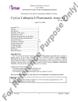
Direct coupling to an IP backbone
Fig. 2.1.1: Infrastructure with IP linking
The device is directly connected to the Ethernet using the 100 Base-T interface. Extension
devices are connected to the TP/FT 10 interfaces.
The LON commissioning tool views the IP port as a logical interface. For communication with
other devices, the device should be bound into an IP channel by means of a configuration server.
Current as of: 14.07.2011
Technical changes reserved!
Page 5 of 91
LON SMI Controller DR 4x16M LoVo
MTN887281
System structure
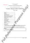
2.1.2
Coupling to a TP/FT 10 line
Fig. 2.1.2: Infrastructure with TP/FT 10 linking
The device is connected to the LON segment using the TP/FT-10 interface.
The LON commissioning tool views the TP/FT-10 port as a logical interface. Other LON devices
that are connected to the same LON segment are managed using the LON management tool.
Current as of: 14.07.2011
Technical changes reserved!
Page 6 of 91
LON SMI Controller DR 4x16M LoVo
MTN887281
General device characteristics
3
General device characteristics
The device offers interfaces for connection of four SMI segments, one LON interface, preferably
for connection of LON control panels and an Ethernet interface for a higher-level system or for
networking with other CNIP - controllers.
In accordance with the SMI standard, up to 16 SMI LoVo motors can be connected to each SMI
interface. The SMI control-voltage is supplied by the interface itself.
LON devices can be installed on the LON interface. These must be held as templates in the
configuration tool. Templates for devices can be added on request.
The functions of the LEDs and the device buttons are listed in the tables below.
3.1
Description of the LEDs
Service
RED
OFF
Flashing at 1 Hz
Loading the firmware.
Application is started – the boot-up process is complete.
Boot-up process (data points created, operating system started)
RUN
GREEN
OFF
Device is supplied with power.
No voltage is present.
CFG
GREEN
OFF
IP stack has been configured.
IP stack has not been configured.
1) Boot-up process running
2) invalid netmask,
3) IP collision.
MSG
OFF
Random flashing GREEN
No data traffic at 100 base T
Data traffic via 100 base T
LINK
GREEN
OFF
100 base T link.
No 100 base T link.
Current as of: 14.07.2011
Technical changes reserved!
Page 7 of 91
LON SMI Controller DR 4x16M LoVo
MTN887281
General device characteristics
CNIP (the CNIP port is relevant only when using a LON over IP network)
GREEN
CNIP port configuration is fully configured and updated.
YELLOW
CNIP port configuration is fully configured but not updated, e.g. because
the configuration server cannot be accessed.
RED
CNIP port configuration is incomplete (i.e. not implemented or the
initialisation has failed). In this case check the CNIP configuration using
the IRC Configurator or check the settings on the configuration server.
OFF
No valid CNIP packet detected.
Flashing RED
CNIP port is unconfigured.
Flashing GREEN or YELLOW
Data traffic via the CNIP.
TP/FT 10
GREEN
RED
OFF
Flashing RED
Flashing YELLOW
Flashing GREEN
IRC*
GREEN
RED
Off
Flashing RED
Flashing YELLOW
Flashing GREEN
SMI 1 – SMI 4
Flashing GREEN
Flashing YELLOW
Flashing RED
Off
GREEN
RED
YELLOW
TP/FT 10 port is configured and online. Heavy data traffic at the port.
TP/FT 10 port is defective or a LON management tool has unconfigured
this device.
TP/FT 10 port is configured and online. No data packet was received.
Data packets were received, but at least one device on this line is
defective.
TP/FT 10 port is unconfigured.
TP/FT 10 port is configured and online. Data traffic at the port and all
devices operating normally.
Port is configured and online. Heavy data traffic at the port.
Port is defective or unused.
Port is configured and online. No data packet was received.
Data packets were received, but at least one device on this line is
defective.
Port is unconfigured.
TP/FT 10 port is configured and online. Data traffic at the port.
Port configured. Data traffic at the port and all addressed SMI devices on
the line are OK.
Manual operating mode active.
At least one SMI device is defective, but data traffic at the port.
1) BUS mode: No data traffic at the port.
2) Manual Mode: tbd
Manual mode Motors on the SMI channel are running.
SMI channel is no longer configured or is defective.
Manual mode / programming mode: Exchanging a SMI motor. Colour
changes when the CHANNEL or ON/OFF/BUS button is pressed.
* This port is not existing at the
SMI Controller
Current as of: 14.07.2011
Technical changes reserved!
Page 8 of 91
LON SMI Controller DR 4x16M LoVo
MTN887281
General device characteristics
3.2
Description of the device buttons
Service
Send a "service message" for each LON channel: FTT10, CNIP).
If this button is kept pressed during the boot-up process (until
the SERVICE LED stops flashing), the standard configuration
will be restored.
Channel
SMI manual mode: Activate manual mode with a long button
push (more than 3 seconds). A further short button push allows
the consecutive SMI channel to be selected (cycle: channel 1channel 2- channel 3- channel 4- all channels).
UP/DOWN/Bus
This button is effective only in SMI manual mode. A short button
push in toggle mode time toggles all devices on the selected
SMI channel UP or DOWN. A long button push (> 3s) is
necessary in order to switch to channel selection mode.
Program
This button allows manual exchange of a defective SMI device.
The command is effective only in manual mode for the
respective channel.
Procedure for exchange:
1) Mount the exchange device.
2) First select manual mode for the respective channel.
3) A long button push on the "Program" button exchanges
the device in the database. Completion of the device
exchange is signalled by the exchanged device "driving".
The device will be exchanged only when a new and a
defective device are found on the channel.
Current as of: 14.07.2011
Technical changes reserved!
Page 9 of 91
LON SMI Controller DR 4x16M LoVo
MTN887281
Installation
4
4.1
Installation
Installing the SMI Controller DR 4x16M LoVo
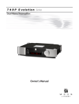
A 24V supply (SELV) is necessary for operating the LON SMI Controller DR 4x16M LoVo.
Connect the devices as described below.
Fig. 4.1: Wiring diagram LON SMI Controller DR 4x16M LoVo
4.2
Installing the SMI lines
SMI stands for "Standard Motor Interface" and is the definition for the standardised digital
operating device interface for an interface standard spanning different companies in the field of
sunblind systems. The SMI standard is described at www.smi-group.com.
SMI supplies a simplified digital interface for sunblind control devices. The intelligent components
communicate in a simple and interference-proof way within a local system with distributed
intelligence. The data communications wiring requires no special features, neither must
terminating resistors be fitted.
SMI is defined for a maximum of 16 individual devices (individual addresses), which can be
divided into a maximum of 16 groups (group addresses).
The SMI Controller provides the bus power of approx. 18VDC on each of its SMI interface (I1/I1+ … I4-/ I4+). The SMI line should be restricted to 350m.
Attention: For operation, the SMI Controller requires a DC 24V supply voltage. It is
necessary to ensure that the SMI Controller and all connected SMI LoVo motors are
powered from one common power supply!
Current as of: 14.07.2011
Technical changes reserved!
Page 10 of 91
LON SMI Controller DR 4x16M LoVo
MTN887281
Installation
Fig. 4.2: Installation scheme of the SMI lines
4.3
Installing the LON line
The TP/FT 10 connection can be used as an alternative in two application cases:
LON control panels or standard LON devices can be connected to this interface as I/O
extensions. This is specially designed for connection of the LON control panels from Schneider
Electric. The management and configuration of these LON devices is performed using the
configuration tool. Links (bindings) between the devices can be created using the configuration
tool, when using the SMI Controller in stand-alone use. Retrospective changes must always be
performed using the configuration tool. In this case the 100 base T interface acts as the interface
for binding into an LNS database. The LON installation guidelines are applicable. We
recommend a maximum extension of 10 LON control panels. When integrating the SMI
Controller into an LNS database, the bindings created by the configuration toll will be overwritten
respectively deleted.
Alternatively the LON SMI Controller can be bound into the LON network using the TP/FT 10
connection. In this case the device functions are depicted at this interface. The LON XIF should
be generated accordingly (setting in the IRC configuration menu, program ID settings). The
configuration of the LON SMI Controller can be performed only via the 100 base T or the RS-232
serial interface.
Current as of: 14.07.2011
Technical changes reserved!
Page 11 of 91
LON SMI-Controller REG 4x16M LoVo (36236-545)
Commissioning
5
Commissioning
After you have switched on the power supply, the device boot-up process starts. This takes a
little time. The process is divided into 2 phases:
1) Self-test: During the self-test the green RUN LED is switched on and the red SERVICE
LED is switched off.
2) Initialising the interfaces: During this phase the green RUN LED remains switched on and
the red SERVICE LED flashes cyclically. All interface LEDs light up red continuously. As
soon as each interface has been tested successfully the respective LED goes out. If an
LED remains red this indicates a fault at the respective interface. In this case please
check the connections.
In normal operation the data traffic over the interfaces is indicated by short flashing of the
respective green LED.
In some cases it may happen that the CNIP LED shows continuous ORANGE. This
indicates that the CNIP configuration server that has been entered cannot be accessed.
This is relevant only if an LNS network is being used.
The installation can be checked by taking the following steps:
1) The LEDs SMI1, SMI2, SMI3, SMI4 should be Off. If an LED lights up red, check the
connections and the power supply of devices for this channel.
2) A long button push (more than 3 seconds) on the "Channel" button activates button
mode. Further short button pushes change the active SMI channel (sequence: 1-2-3-4all). The "UP/DOWN/BUS" button allows all connected SMI devices to be driven. A short
button push on the "Channel" button takes you to the next channel. A long button push
(more than 3 seconds) on the "Channel" button exits button mode.
For easy commissioning we recommend connection to the Ethernet network using the "100 base
T" interface.
For direct connection between a PC and the LON SMI Controller please use a crossover cable
for Ethernet.
Current as of: 14.07.2011
Technical changes reserved!
Page 12 of 91
LON SMI Controller DR 4x16M LoVo
MTN887281
Configuration
6
6.1
Configuration
IP configuration
It is preferable that the configuration is performed using the "100 base T" interface. The device IP
address is factory-set to 192.168.1.111.
Before you can address the standard IP address you must set it up in your computer, providing
your computer has as IP address for a subnet that differs from 192.168.1.xxx.
To do this, open a "command tool" and enter the following route instruction:
1) Windows START -> Execute
2) Command.com
3) Route add 192.168.1.111 %COMPUTERNAME%
Alternatively you can add an IP address for the same subnet to your local TCP/IP settings:
Windows START -> Network connection -> LAN connection -> Properties -> Internet protocol
(TCP/IP) -> Properties -> Extended
The IP addresses of the LON SMI Controller must not be identical to those for other devices on
the network.
Fig. 6.1: Setting the IP address of your computer in the system control
Current as of: 14.07.2011
Technical changes reserved!
Page 13 of 91
LON SMI Controller DR 4x16M LoVo
MTN887281
Configuration
6.2
Installing the configuration tool
A pre-requirement for installing the configuration tool is an operating system that supports Java
JRE 1.4.x. Windows XP, Windows 2000, Linux (release 10.x) are platforms that have been tested
for this.
Before installing the configuration tool, please install on your Windows platform Java(TM) 2
Runtime
Environment,
Standard
Edition
1.4.2_12
(http://java.sun.com/j2se/1.4.2/download.html -- J2SE v 1.4.2_12 JRE) or a more recent
version.
After this, perform the setup "irc_install_xxxx" and follow the instructions in the installation
program.
We recommend the configuration tool is used over the "100 base T" interface (Ethernet)!
Alternatively the configuration tool can communicate over the RS232 interface, but its
functionality will be restricted. For this the "Java Communication Extension" is necessary. Please
use the installation supplied. Open a "command tool" and perform the following instruction in the
respective directory
1) Windows START -> Execute
2) Command.com
3) java -jar comm_install.jar
Alternatively it is sufficient to double click on this file. However no acknowledgement is supplied
in this case.
6.3
Installation und starting the IRC Project Manager and IRC Configurator
Fig. 6.3.1 und 6.3.2: Installation of the SE Configurator Software and selection of a project directory
For installing and managing of projects the SE Configurator software uses the Project Manager.
This tool is needed to create new projects and to open and manage existing projects.
Current as of: 14.07.2011
Technical changes reserved!
Page 14 of 91
LON SMI Controller DR 4x16M LoVo
MTN887281
Configuration
At the installation process of the SE Configurator Software, the routine saves the SE Configurator
in a selected directory. If there is a SE Configurator software still existing at the computer, it is
advisable to use the same directory to update the previous version. Otherwise existing links may
activate old and limited software functions.
After starting the Project Manager you can initialize the first project at the register Project/Create
New and giving a related project name. At Project/Open you can open this project and do the
requested product selection with a click on
(see arrow).
Fig. 6.3.3: Project start and related product selection
When initializing a new project, a copy of the folder ‚template’ will be created. It contains all
available samples and standard configurations.
Each project contains and manages only one SMI Controller. Additional Controllers have to be
integrated into new projects. The Project Manager implements the function to copy existing
projects and therefore use as templates. Later on the SE Configuration Manager allows the
function ‘Save copy as’ to create copies of the current running project.
The configuration of the device and related project at the Project Configurator can be activated
by a double click on the designated device.
Current as of: 14.07.2011
Technical changes reserved!
Page 15 of 91
LON SMI Controller DR 4x16M LoVo
MTN887281
Configuration
Fig. 6.3.4: Start of the SE Configurator
Each project is protected by a password.
New projects are protected by the user name and password:
User name: admin
Password: admin
Fig. 6.3.5: Input of the user password
The SE Configurator now starts for a configuration of the requested project. Now user name and
password can be changed at the register ‚User’ - ‚Change password’.
Current as of: 14.07.2011
Technical changes reserved!
Page 16 of 91
LON SMI Controller DR 4x16M LoVo
MTN887281
Configuration
Fig. 6.3.6: Current Project configuration
At the status line the current ‚online’ or ‚offline’ status of the Controller can be detected. Only the
‚online’ -modus signalises access of the Project Configurator to the Controller.
The current project view (Fig. 6.3.6) shows the ‘virtual’ devices in a tree structure. These ‘virtual’
devices are divided into their related device interfaces. They are a copy of the physical devices at
the SMI and TP/FT-10 interfaces and their internal functions.
At the SMI line you will find the ‚virtual’ device ‚SMI Group Actuator’ including 16 ‚Actuator’objects related to the ‚Blind Actuator’–profile at LonMark. One actuator-object corresponds to one
SMI group. At each SMI channel only one ‚SMI Group Actuator’ is possible.
At the category ‚Internal blocks’ basically controller functions can be found. Due to the uniform
structure, these functions are shown as ‚virtual’ devices, each containing multiple function object
of the same type: e.g. each ‚Blind Controller’ contains 4 functional blocks related to the LonMarkprofile ‚Sunblind Controller’ for controlling sunblinds.
When closing the SE Configurator and Project Manager the project data always has to be saved
with the function „save“. Otherwise new configurations get lost.
Current as of: 14.07.2011
Technical changes reserved!
Page 17 of 91
LON SMI Controller DR 4x16M LoVo
MTN887281
Creating a project
7
Creating a project
To create a new database configuration or to edit the current configuration, switch to the "Device
Selector".
Fig. 7.1: Creating a device configuration (function) using the "Device Selector"
Down the left side of the "Device Selector" you will find the device templates. Use "drag&drop" or
the arrow symbols to move the device templates into the "device list" or to remove devices that
have been created (warning: This changes the LNS interface so that it is no longer compatible
with an existing LNS interface. In this case the program ID should be modified to suit, see IRC
configuration). For all interfaces, insert the devices that are connected to the device. When the
"Device Selector" is exited (either with the "Save" button or the "Close" button), the selected
project configuration is saved in the database.
Current as of: 14.07.2011
Technical changes reserved!
Page 18 of 91
LON SMI Controller DR 4x16M LoVo
MTN887281
Creating a project
7.1
Configuration of the function objects
Select "Configure" in the context menu (right mouse button) to call up the configuration view. In
general you will find the configuration parameters listed here in tabular form.
Fig. 7.1.1: Context menu for the function objects
Current as of: 14.07.2011
Technical changes reserved!
Page 19 of 91
LON SMI Controller DR 4x16M LoVo
MTN887281
Creating a project
Fig. 7.1.2: Configuration parameters of the function objects
Enter the desired value in the "New value" field. Quit the input with "Return" or the "!" symbol and
the value will be written to the device, provided it is "online". Otherwise the configurations will be
written at installation. The configuration can also be written to the device using the device context
menu: "Info View" -> "Service" -> "Write CP file". The command "Read CP file" allows the current
device configuration to be read.
Fig. 7.1.3: Service menu for the device view
More complex devices can be configured using special views. You will find a description below of
the device functions for which a special configuration view exists.
Current as of: 14.07.2011
Technical changes reserved!
Page 20 of 91
LON SMI Controller DR 4x16M LoVo
MTN887281
Creating a project
7.2
LON control panels
Appendix C contains a list of the devices that are supported by the LON SMI Controller.
The configuration regarding control panels consists largely in the selection of operating functions
and the assignment of control buttons and LEDs. Fur button controls the following function
objects are available at the devices: Switch, Scene Panel, Occupancy Sensor. There follows a
short description of these function objects. More detailed information can be found in the device
documentation for the respective control panel.
Use the "Plug-Ins" context menu for any object to select the application module to be used. The
respective view will open.
7.2.1
Switch Object
First select the function. Select the desired button function from the symbol menu and use
"drag&drop" to move this to the desired button. The selection can be removed using the "Eraser"
symbol or can be overwritten by other symbols.
The selection of the LED is performed by double clicking on the LED symbol. After they have
been assigned, the selected buttons are highlighted in red.
Current as of: 14.07.2011
Technical changes reserved!
Page 21 of 91
LON SMI Controller DR 4x16M LoVo
MTN887281
Creating a project
7.2.2
Scene Panel Object
For configuration of scene calls, first highlight the desired button and then enter the respective
scene number into the "Button commands menu" field. Press the "Enter" button to load the value.
To delete an existing scene call, highlight the respective button; the configured scene will appear
in the "Button commands menu" field. Delete this value, so that the field no longer shows an
entry. Then press the "Enter" button to delete the existing value.
7.2.3
Occupancy Panel Object
Select the desired button function from the symbol menu and use "drag&drop" to move this to the
desired button. The selection can be removed using the "Eraser" symbol or can be overwritten by
other symbols.
The following functions are available for selection:
Occupied (OC_OCCUPIED)
Unoccupied (OC_UNOCCUPIED)
Standby (OC_STANDBY)
Bypass (OC_BYPASS)
Invalid value (OC_NUL)
Current as of: 14.07.2011
Technical changes reserved!
Page 22 of 91
LON SMI Controller DR 4x16M LoVo
MTN887281
Creating a project
7.2.4
fb_0-Object
The configuration parameters for general device functions, in particular those for setting display
behaviour common to multiple objects, can be found in the context menu of the fb_0-Object (->
Configure). The detailed description of the configuration parameters can be found in the device
documentation for the respective (control) device.
Current as of: 14.07.2011
Technical changes reserved!
Page 23 of 91
LON SMI Controller DR 4x16M LoVo
MTN887281
Creating a project
7.3
Simulation and test
You can describe and read the network variables directly in order to test their function. Select the
item "Browse" in the context menu of the respective function object. The variables view will open.
First activate the "Polling"
"Value" column.
option. You will then see the current values of the variables in the
Under the "New Value" item you can set the network input variables. You can also use the value
inspector for this
.
Current as of: 14.07.2011
Technical changes reserved!
Page 24 of 91
LON SMI Controller DR 4x16M LoVo
MTN887281
Creating a project
7.4
Saving a project
The current configuration can be saved with File -> Save Database. It is absolutely essential to
save project changes during editing and when quitting the configuration tool.
File -> "Save Database Copy as..." allows a copy of the current project database to be made.
This copy can be the basis for configuration of another device.
7.5
Basic configuration
The LON SMI Controller is factory-set to a standard configuration (IP address: 192.168.1.111).
This is also the standard setting of the SE Configurator, so that the device can be addressed
during first commissioning.
If the device is directly connected to the computer (not through a switch or hub) a crossover
network cable should be used for the connection. Note: Be sure always only to connect a device
with the standard address, since otherwise address conflicts can arise.
The IP address of the device with which it will be addressed by the SE Configurator is entered in
"Options -> IRC configuration -> Connect to".
Current as of: 14.07.2011
Technical changes reserved!
Page 25 of 91
LON SMI Controller DR 4x16M LoVo
MTN887281
Creating a project
7.6
Configuration of the network address
Each device requires a unique IP address for binding into an IP network. To set the IP address,
go to the menu "Options Æ IP Configuration".
Fig. 7.6: IP settings
The "Load" button is used to read the current device settings from the device.
Assigning an individual address can be done either dynamically using the "Enable DHCP" setting
or from static addresses assigned by the network administrator. In the latter case please enter
the IP address, the netmask and the default gateway. Host name and domain name are not
required in the current firmware version.
Up to 3 domain name servers can be entered. The DNS server entries are currently not used. In
many DHCP configurations however it may be necessary to enter a specific host name. Please
contact your system administrator and ask about the necessary DHCP settings.
Under NTP (Network Time Protocol) up to three servers for synchronising the internal clock can
be entered.
Enter the standard communication port (27111) in the "Communication port" field. In exceptional
cases this communication port may be blocked by a firewall. In this case, please enter a free
communication port.
After input of the IP address the status "online" should henceforth be displayed in the status bar.
Current as of: 14.07.2011
Technical changes reserved!
Page 26 of 91
LON SMI Controller DR 4x16M LoVo
MTN887281
Creating a project
7.7
Addressing the extension modules at TP/FT 10
Select "Extension Lookup" in the context menu (right mouse button) for the TP/FT 10 line, to
address the devices connected to the TP/FT line.
In this process you can bind in devices that previously had been created. To do this proceed as
follows:
1) Select "Start".
2) Wait until the user message "Waiting for service pin (1 minute)" appears.
3) Actuate the "service pin" on the first LON device on the TP/FT 10 line.
Current as of: 14.07.2011
Technical changes reserved!
Page 27 of 91
LON SMI Controller DR 4x16M LoVo
MTN887281
Creating a project
4) When the device has been successfully identified, both the neuron ID and the program ID
will be shown in the list.
5) If the program ID does not match the anticipated program ID, the correct application must
be loaded into the device that was found. The application is loaded under "Options" ->
"Info View" -> "Service".
6) Repeat steps 2 and 5 for all LON devices connected to the TP/FT 10.
7) After you have addressed all the devices, end the process with "Stop", close the window
and return to the project view. The addressed devices now appear brown in the tree view.
Current as of: 14.07.2011
Technical changes reserved!
Page 28 of 91
LON SMI Controller DR 4x16M LoVo
MTN887281
Creating a project
7.8
Installation procedure
After you have created all the devices in the database and have addressed the TP/FT 10 line or
IRC line, the project database must be loaded into the LON SMI Controller. Amongst other
things, this generated the "virtual devices" and also creates the network variables.
Start the installation process with "Tools" Æ "Installation Procedure". The "virtual devices" are
then loaded into the device. Depending on the size of the database, this process may take
several minutes. On completion the program reports the successful configuration.
Current as of: 14.07.2011
Technical changes reserved!
Page 29 of 91
LON SMI Controller DR 4x16M LoVo
MTN887281
Creating a project
Fig. 7.8.1: Writing the configuration into the device
After the configuration is finished, the parameters will be written into the device.
Fig. 7.8.2: Writing the configuration into the device
Current as of: 14.07.2011
Technical changes reserved!
Page 30 of 91
LON SMI Controller DR 4x16M LoVo
MTN887281
Creating a project
Fig. 7.8.3: Writing the configuration into the device
7.9
Commissioning the SMI lines
For commissioning the SMI lines the device must be "online" (see status bar). The SMI devices
must be connected and in operation.
Highlight the SMI line to be configured (line 0, line 1, ...). Then select " SMI addressing" in the
context menu (right mouse button).
Current as of: 14.07.2011
Technical changes reserved!
Page 31 of 91
LON SMI Controller DR 4x16M LoVo
MTN887281
Creating a project
Fig. 7.9: SMI line context menu
7.9.1
Addressing the SMI devices
The commissioning window for the selected SMI line opens. Click on the symbol "Start SMI line
. This starts the search process for connected SMI devices. The devices that
scanning"
were found, together with devices contained in the database (e.g. from a previous scan of the
SMI line) will be listed, and their device type and status displayed. A name for each device can
be edited in the "Name" column. This will be saved as a configuration parameter.
Current as of: 14.07.2011
Technical changes reserved!
Page 32 of 91
LON SMI Controller DR 4x16M LoVo
MTN887281
Creating a project
Fig. 7.9.1: SMI addressing
7.9.1.1 Wink a SMI device
The physical position of the SMI devices can be found by the "Wink" command. The selected
devices move and thus could be identified.
7.9.1.2 Assigning the group address
The assigning of motors to one of the 16 available groups is performed by activating the
checkbox 0...15. Each device can be assigned to only one group. The selected group
corresponds to the object index of the "SMI Group Actuator".
7.9.1.3 Direct actuation of SMI devices
For test purposes the groups can be controlled individually or collectively by a "broadcast" to all
devices.
7.9.1.4 Network Recovery Function
If the LON SMI Controller is inserted into an existing SMI network with motors that have already
been configured (e.g. on exchanging the controller), you can press the "Recover" button in the
Current as of: 14.07.2011
Technical changes reserved!
Page 33 of 91
LON SMI Controller DR 4x16M LoVo
MTN887281
Creating a project
"SMI addressing" menu to read the configuration of the entire SMI network into the device
database. This contains all the address information stored in the motor.
7.9.1.5 Exchanging a SMI device.
To exchange a SMI device, proceed as follows:
1) Installing a new SMI device
2) Highlight the device to be exchanged (this should be shown in the status field as "?") and
press the "Replace" button. The device will now be replaced with the unconfigured device.
Note that for this exchange process only one unconfigured SMI device is connected.
3) Repeat steps 1 and 2 for further SMI devices to be exchanged.
If several unconfigured SMI devices are found, the process will crash. Therefore make sure that
only one unconfigured SMI device is connected, or configure these devices using the standard
addressing procedure and remove the defective devices from the database.
7.9.1.6 Manually exchanging a SMI device
It is not absolutely necessary to use the SE Configurator when exchanging one SMI device. You
can use the device buttons for this. The pre-requirement however is that this allows only a
defective device to be exchanged for an unconfigured device. Other cases require the use of the
SE Configurator. If there are several defective SMI devices, it will always be the first short
address that is replaced with the new SMI device.
Proceed as follows:
1) Install the exchange device
2) Perform a long button push on "Channel" to switch into manual mode. Then perform a
short button push to select the respective SMI channel.
3) Test the connection by pressing the "UP/DOWN/BUS" button
4) Press the "Progr" button for longer than 3s.
5) When the exchange has been successfully completed, the LED of the respective SMI
channel lights up orange (from version 0.1.3.) and the SMI device that was found "waves"
for one cycle. There is no reaction otherwise. (e.g. if more than one unconfigured device
was found on the line).
6) Perform a long button push on "Channel" to switch out of manual mode.
7.10 Creating binding links
This function is required only if the LON SMI Controller is not bound into a LON network!
Until now you have set up connected devices with their associated function objects on the LON
SMI Controller. The application of the LON SMI Controller is set up by creating a binding link
between the function objects and the desired overall function. The function objects contain
Current as of: 14.07.2011
Technical changes reserved!
Page 34 of 91
LON SMI Controller DR 4x16M LoVo
MTN887281
Creating a project
network variables for communication with other function objects. Network variables "nviYYxxx"
are input variables and "nvoYYxxx" are output variables. The connections between the input
variables and the output variables are created by "binding". There can only ever be one input
variable and one output variable of the same type bound to each other. The type information can
be found as the "tool type" by pointing the cursor to the network variables.
The bindings between the object variables can be created using the Binding Editor.
Proceed as follows to create and edit bindings:
1) When "Show Bindings" is selected, the Binding Window opens.
2) Use the "Create New Binding" button to select the desired binding type. (Currently only
the binding type "Binding between two data points" is supported.) A binding template will
open with wild cards for the network variables to be bound.
3) In the left hand window, select from the project view the first network variable, drag it to a
free position in the binding template and drop it.
4) Then select the corresponding network variable and drag this to another free position in
the binding template. The variables must both be of the same type. Network variables of
differing types cannot be bound to each other.
5) For further binding links, repeat steps 2 to 4.
6) Once all binding links have been generated you can load them to the LON SMI Controller
by pressing the "Create Bindings" button.
Current as of: 14.07.2011
Technical changes reserved!
Page 35 of 91
LON SMI Controller DR 4x16M LoVo
MTN887281
Creating a project
Fig. 7.10: Creating binding links in stand-alone mode
Current as of: 14.07.2011
Technical changes reserved!
Page 36 of 91
LON SMI Controller DR 4x16M LoVo
MTN887281
Creating a project
7.11 Application in a LON network
7.11.1 Creating a LON template (XIF)
Pre-requirement for an implementation of the LON SMI Controller into a LON network is the
availability of a device template (XIF). After a project has been created and loaded into the
device, a device template (XIF) can be created. To do this, select "File => Export XIF" in the
folder and enter the desired path for saving.
This XIF file can be used to integrate the controller into a LON network management tool. It
should be noted that configuration within this firmware version can only be performed by use of
the configuration tool.
Current as of: 14.07.2011
Technical changes reserved!
Page 37 of 91
LON SMI Controller DR 4x16M LoVo
MTN887281
Creating a project
7.11.2 Program ID settings
For binding into a LON network further settings must be performed beforehand.
The LON SMI Controller can be bound into a LON network either using EIA-852 (Lon over IP) or
using EIA-709 (TP/FT). The setting of the respective parameters is performed under "Options"
=> "IRC Configuration" => "Program ID settings" -> "Main side".
The setting "CNIP" indicates that the binding into the LON network is performed using the "100
Base T" connection. The setting "FT10" indicates that the binding into the LON network is
performed using the TP/FT 10 connection. The program ID is automatically selected in
accordance with the interface that is selected, since the transceiver settings are coded into it.
For further management of the program ID the "version" can be modified to suit. This modification
is necessary if an existing "template" already integrated into the LON network must be
retrospectively changed.
Fig. 7.11.2: Basic settings
7.11.3 Structure of an IP channel
IP is an acronym for Internet Protocol. IP is part of the TCP/IP protocol family (Transmission
Control Protocol/Internet Protocol). The IP is the general program basis used for a worldwide
exchange of computer messages by the Internet and within many LANs (Local Area Networks)
and WANs (Wide Area Networks).
A LonWorks/IP channel is a communication medium which conveys IP packets that contain
LonTalk packets. If the computer on which the LON commissioning tool is running is connected
to a LONWORKS/IP channel, it must have an IP network interface (such as an Ethernet network
card or a modem with PPP software) which it can use for communication with the physical
network (extract from the LonMaker manual 1-11, 1-12).
Current as of: 14.07.2011
Technical changes reserved!
Page 38 of 91
LON SMI Controller DR 4x16M LoVo
MTN887281
Creating a project
Note: It is essential to have a configuration server for setting up an IP channel. A configuration
server is not a component of the LON SMI Controller. We refer at this point to the use of the
configuration servers from Echelon and Loytec.
First create a LONWORKS/IP interface on the computer on which the LON commissioning tool is
installed. To create a LONWORKS/IP interface, proceed as follows:
1) Point to Settings in the Windows Start menu, then select the control panel. Windows
system control will open.
2) Double click on the system control application LNS IP Configuration (LonWorks/IP
Channels) Windows panel control.
3) Click on Add. The dialog field Add an IP Device will open.
4) Input a unique name for the computer and check whether the displayed IP address
tallies with your network card. Leave the port address as 1628.
5) Click on OK. The dialog field Add an IP Device will close.
6) Click on OK. The LNS IP configuration system control application will close.
Further information can be found in the Help file for the LNS IP configuration system
control application.
Define the LONWORKS/IP channel and the devices in the configuration server. The procedure to
use depends on the configuration server in question. In this respect we refer to the respective
data sheets issued by Echelon and Loytec.
The LonMaker computer is not fully commissioned on the LONWORKS/IP channel until you
execute the LonMaker tool. Further information can be found in the Help file for the Loytec
configuration server or in the user manual for the i.LON configuration server.
Current as of: 14.07.2011
Technical changes reserved!
Page 39 of 91
LON SMI Controller DR 4x16M LoVo
MTN887281
Creating a project
7.11.4 CNIP settings
The participants on the IP channel are managed by a "configuration server". Enter under "CNIP
settings" the name under which you will log in this device at the configuration server, and enter in
"Config server host" the IP address of the configuration server. The port settings should be made
as listed below.
7.12 Tools
You will find the following service programs in the "Tools" folder:
•
•
•
"Check connector": Shows whether the device is online.
"IRC devices": Shows the current configuration of the device, in case it is "online".
"IRC Statistics": Shows general information on the device. ‘Version’ shows the currently
loaded firmware version.
Current as of: 14.07.2011
Technical changes reserved!
Page 40 of 91
LON SMI Controller DR 4x16M LoVo
MTN887281
Creating a project
•
•
"Clear IRC Tables": Deletes all configuration entries in the device. If a project requires all
existing devices to be deleted, please first use this function.
"Upload IRC Firmware": Loads new firmware. Loading the firmware deletes the
configuration data. The device configuration (Installation Procedure) must be renewed (as
it must after LNS installations).
Fig. 7.12: Service programs
7.13 Configuration using the Web browser
The major settings can also be performed using the integral Web server. The following Web
browsers are supported: Firefox 1.5 and Internet Explorer from version 6.0.
Enter the IP address of the device (default 192.168.1.111).
Note that in this firmware version it may take a few seconds to generate the pages, since these
are created dynamically.
You can then navigate through the various subjects:
Current as of: 14.07.2011
Technical changes reserved!
Page 41 of 91
LON SMI Controller DR 4x16M LoVo
MTN887281
Creating a project
7.13.1 IP SETTING
Set the new IP configuration of the device here: IP address, netmask and gateway - all other
settings are optional. The new settings become active only when the device is restarted.
Fig. 7.13.1: Setting the IP configuration: IP address, netmask, gateway ...
Current as of: 14.07.2011
Technical changes reserved!
Page 42 of 91
LON SMI Controller DR 4x16M LoVo
MTN887281
Creating a project
7.13.2 CNIP SETTING
If the device is used in a LON over IP network, the device is logged on to a "Configuration
Server". Enter here the IP address of the "Configuration Server".
Fig. 7.13.2: Setting the IP address of the configuration server when a device is used in a LON over IP network
Current as of: 14.07.2011
Technical changes reserved!
Page 43 of 91
LON SMI Controller DR 4x16M LoVo
MTN887281
Creating a project
7.13.3 LOG SETTING
System and debug information can be saved temporarily in the local file system. Two files are
available for this purpose; these are described successively as ring memories. Select here the
sort of information that you wish to save.
Fig. 7.13.3: Setting the log function. There are two files available; these are described as ring memories. In the
standard setting only system information is saved (the recommended setting).
Current as of: 14.07.2011
Technical changes reserved!
Page 44 of 91
LON SMI Controller DR 4x16M LoVo
MTN887281
Creating a project
7.13.4 TIME
If you have not entered an NTP server from which the system time can be obtained, you can
here manually set the system time.
Fig. 7.13.4: Setting the time manually
Current as of: 14.07.2011
Technical changes reserved!
Page 45 of 91
LON SMI Controller DR 4x16M LoVo
MTN887281
Creating a project
7.13.5 LIST DEVICES
In this list you will find the "virtual" devices that have been configured. Press the "Get Status"
button to obtain a view of the status of the "virtual" devices (see Fig. 7.13.5.1).
Fig. 7.13.5.1: List of the virtual devices
Current as of: 14.07.2011
Technical changes reserved!
Page 46 of 91
LON SMI Controller DR 4x16M LoVo
MTN887281
Appendix A: Description of the function objects
8
8.1
Appendix A: Description of the function objects
LonMark®-object Blind Controller
NodeObject
LonMark Object #0
nviRequest
SNVT_obj_request
nvoStatus
SNVT_obj_status
nvoFileDirectory
SNVT_address
CP - UCPTmaxRandomDelay
SbController [4]
LonMark Object #5
nviBClocalCtrl
SNVT_setting
nvoBCsunblind
SNVT_setting
nviBCgroupCtrl
SNVT_setting
nvoBCstates
SNVT_state
nviBCscene
SNVT_scene
nvoBCswitchFB
SNVT_switch
nviBCsetOverride
SNVT_setting
nviBCsunLux
SNVT_lux
nviBCindoorTemp
SNVT_temp_p
nviBCoccSensor
SNVT_occupancy
CP - UCPTlocalCtrlTime
CP - UCPTgroupCtrlPriority
CP - UCPTdefaultOccupancy
CP - UCPTstandbyAsOccupied
CP - UCPTluxHystHigh
CP - UCPThighLuxDelay
CP - UCPThighLuxSetting
CP - UCPTluxHystLow
CP - UCPTinstantLowLuxSetting
CP - UCPTlowLuxDelayMin
CP - UCPTlowLuxSetting
CP - UCPTtempHystHigh
CP - UCPThighTempSetting
CP - UCPTtempHystLow
CP - UCPTlowTempSetting
CP - UCPTirradianceHystHigh
CP - UCPTirradianceHystLow
CP - UCPTautoUpdatePause
CP - UCPTorientation2d
CP[10] - UCPTskyline
CP - UCPTzeroAltitudePanelAngle
CP - UCPTzeroPanelAngleAltitude
CP - UCPTminTrackingAngle
CP - UCPTmaxTrackingAngle
CP - UCPTminDeltaTrackingAngle
CP - UCPTverticalPanel
CP[5] - UCPTsceneKeeperSetting
CP - UCPTstateMaskOn
CP - UCPTstateMaskNul
SharedIn
LonMark Object #3
nviSIsolar
UNVT_???
nviSIhvacMode
SNVT_hvac_mode
CP - UCPTsolarByMessage
CP - UCPTmessageCode
Current as of: 14.07.2011
Technical changes reserved!
Page 47 of 91
LON SMI Controller DR 4x16M LoVo
MTN887281
Appendix A: Description of the function objects
8.1.1
Introduction
The ‚Blind Controller’ object allows control of ‘Sunblind Actuator’ objects. The ‚Blind Controller
Object’ realises these 2 basic functions:
1. Priority control (override, group control, local and scene control, internal automatic)
2. Automatic control (glare shield control, shading by environment, slat tracing, irradience
control, temperature control)
3. Local control
8.1.2
Priority Control
Network input variables nviBClocalCtrl[i], nviBCscene[i], nviBCgroupCtrl[i] and nviBCoverride[i]
manage the transmission of commands via nvoBCsunblind[i] in following scheme (1 means
highest priority):
Priority
Function
NV
1
Safety function
(not used, only for compatibilty with former ‘Blind Actuators’)
2
Global Control
nviBCoverride[i]
3
Group Control
If UCPTgroupCtrlPriority[i] = GCP_PRIORITY_3,
nviBCgroupCtrl[i] works with priority 3.
4
Local control and scene
control
nviBClocalCtrl[i]
nviBCscene[i]
5
Internal automatic control
Internal automatic via internal parameters (Glare shield control,
temperature control, irradiance control)
If UCPTgroupCtrlPriority[i] = GCP_PRIORITY_5, external
automatic via nviBCgroupCtrl[i] is active while nviBCgroupCtrl[i]
not equal to SET_NUL, otherwise work internal automatic
In case of Prio 2 or Prio 3 control all network variable input with lower priority are disabled unless
prioritised network variable input has been released via SET_NUL command. Only if
SCPTlocalCtrlTime[i] not equal to 0, local control blocks lower priority for this time. When time
expires, local control is released and lower priority re-enabled.
After release a valid command, an input variable with lower priority is then transmitted as valid
command onto nvoBCsunblind[i] (except of relative commands).
By default, Group Control is of priority 3 (UCPTgroupCtrlPriority[i] = GCP_PRIORITY_3). The
priority could be decreased to 5 in case a group command should be allowed to be oversteered
by a local command via nviBCsunblind[i].
Protection against simultaneous operation in the whole building UCPTmaxRandomDelay
configures a randomized delay of operation. UCPTmaxRandomDelay delays the reactions to all
network input variables (except of nviBClocalCtrl[i] and nviBCscene[i]) updates.
In case of internal automatic control any command via nviBClocalCtrl[i] or nviBCscene[i] can
override the automatic for the time configured within SCPTlocalCtrlTime[i]. With SET_NUL
command the override function is being cancelled.
Current as of: 14.07.2011
Technical changes reserved!
Page 48 of 91
LON SMI Controller DR 4x16M LoVo
MTN887281
Appendix A: Description of the function objects
Example for UCPTgroupCtrlPriority[i] = CP_PRIORITY_5:
SCPTlocalCtrlTime[i] = 5minutes.
nviBClocalCtrl[i] is set to SET_STATE 100% 0
nvoBCsunblind[i] is set to SET_STATE 100% 0 too.
During the next 5 minutes the internal automatic is blocked. This means: nviBCgroupCtrl[i] is
ignored for 5 minutes, occupancy control and HVAC control too.
8.1.3
Internal automatic Control
The internal automatic is set by the following functions:
Name of automatic function Subfunctions
NV
Notes
Shading by environment
-
nviSIsolar (SharedIn)
Subject to charges
Occupancy control
HVAC control
Glare shield
nviSIsunLux (SharedIn)
nviBCsunLux[i]
Only if nviBCoccupancy[i] = OC_OCCUPIED,
OC_BYPASS or OC_STANDBY by
UCPTstandbyAsOccupied sets to TRUE.
Room temperature
nviBCindoorTemp[i]
Only if nviBCoccupancy[i] =
OC_UNOCCUPIED or OC_STANDBY by
UCPTstandbyAsOccupied sets to FALSE
and
nviSIhvacMode[i] is not equal to
HVAC_COOL.
Irradiance control
nviSIsunLux (SharedIn)
nviBCsunLux[i]
Only if nviBCoccupancy[i] =
OC_UNOCCUPIED or OC_STANDBY by
UCPTstandbyAsOccupied sets to FALSE
Slat tracing
-
nviBCgroupCtrl[i]
nviBCoverride[i]
nviBCscene[i]
nviBClocalCtrl[i]
Only if .function=SET_STATE and
.rotation>=360 is processed.
Accepting external automatic
as internal automatic
-
nviBCgroupCtrl[i]
Only if UCPTgroupCtrlPriority[i] =
CP_PRIORITY_5 otherwise external
automatic has higher priority.
Automatic control is disabled, when nviBCoccupancy[i] is not equal to OC_OCCUPIED,
OC_UNOCCUPIED, OC_STANDBY or OC_BYPASS.
UCPTautoUpdatePause defines the minimum time for the next automatic command and protects
the blinds against overload.
Current as of: 14.07.2011
Technical changes reserved!
Page 49 of 91
LON SMI Controller DR 4x16M LoVo
MTN887281
Appendix A: Description of the function objects
8.1.4
Occupancy control
The following table shows the occupancy controlled modes:
External automatic sends the commands to controller via nviBCgroupCtrl[i].
nviBCGroupCtrl[i].function
not equal to SET_NUL
UCPTgroupCtrlPriority[i]
CP_PRIORITY_3
CP_PRIORITY_5
equal to SET_NUL
CP_PRIORITY_3
CP_PRIORITY_5
nviBCoccupancy[i].state
OC_OCCUPIED
OC_BYPASS
OC_STANDBY by
UCPTstandbyAsOccupied
sets to TRUE
External automatic
External automatic
Glare shield control
OC_UNOCCUPIED
OC_STANDBY by
UCPTstandbyAsOccupied
sets to FALSE.
External automatic
HVAC with irradiance
control and
temperature control
HVAC with irradiance
HVAC with irradiance
control and temperature control and
control
temperature control
The rest
External automatic
External automatic
Internal automatic is off
Glare shield control
Internal automatic is off
After‚ reset‘ value of UCPTdefaultOccupancy will be adopted. If nviBCgroupCtrl[i].function =
SET_NUL and nviBCoccupancy[i] = OC_OCCUPIED, glare shield is active.
OC_STANDBY operates as described in UCPTstandbyAsOccupied.
OC_BYPASS operates equal to OC_OCCUPIED.
8.1.5
Glare shield control
Is active only if nviBCoccupancy[i].state = OC_OCCUPIED, OC_BYPASS or OC_STANDBY
(only if UCPTstandbyAsOccupied is set to TRUE).
Operation mode ‚glare shield‘ requires bases on solar brightness value. This value is provided by
nviSolar (shared and if nviBCluxLevel[i] is not bound, overrides it) or by nviBCluxLevel[i] (if
bound, has higher priority as nviSIsolar, otherwise can be overridden by new update of
nviSIsolar).
If the luminance is exceeding the threshold defined within UCPTluxHystHigh the blinds will be
driven into the position configured in UCPThighLuxSetting. A delay can be defined within
UCPThighLuxDelay. This delay avoids multiple operation which might annoy the occupant.
In case of luminance lower than defined within UCPTluxHystLow, the blind will move into the
position defined within UCPTinstantLowLuxSetting (for example slats in horizontal position). After
the time configured in UCPTlowLuxDelay has been expired the blind will move into position
configured in UCPTlowLuxSetting. If luminance is in an intermediate value, the blinds won’t drive
by automatic.
8.1.6
HVAC support
HVAC support is active only if nviBCoccupancy[i].state = OC_UNOCCUPIED or OC_STANDBY
(only if UCPTstandbyAsOccupied is set to FALSE).
nviSIhvacMode allows to distinguish between heating and cooling mode of the HVAC system.
Current as of: 14.07.2011
Technical changes reserved!
Page 50 of 91
LON SMI Controller DR 4x16M LoVo
MTN887281
Appendix A: Description of the function objects
nviSIhvacMode = HVAC_COOL = cooling mode
In cooling mode blind will operate to minimize the irradiance into the building.
If the luminance is exceeding the threshold defined within UCPTirradianceHystHigh the blinds will
be driven into the position configured in UCPThighTempSetting. A delay can be defined within
UCPThighLuxDelay.
In case of luminance lower than defined within UCPTirradianceHystLow the blind will move into
the position defined within UCPTlowTempSetting. If luminance is in an intermediate value, blind
won’t drive by automatic.
nviBCindoorTemp[i] doesn’t have any influence on this mode.
nviSIhvacMode not equeal HVAC_COOL =heating mode (HVAC_HEAT, HVAC_NULL...)
In heating mode the blinds are controlled according to maximize the room temperature
nviBCindoorTemp[i] within the gap defined by UCPTtempHystLow and UCPTtempHystHigh.
These values should analogue to the setpoints defined within the ‚space comfort controller‘:
•
UCPTtempHystLow = unoccupied_heat (e.g.. 21°C)
•
UCPTtempHystHigh = occupied_cool
(e.g. 23°C)
Overheating case:
If the space temperature exceeds the setpoint UCPTtempHystHigh and irradiance
UCPTirradianceHystHigh, the blinds are moved into position UCPThighTempSetting.
Undercooling case:
In case of lower space temperature blinds move into position UCPTlowTempSetting.
If no valid value nviBCindoorTemp[i] is available the behaviour is equal to overheating case.
8.1.7
Slat tracing (not supported)
Slat tracing gets active always if .function = SET_STATE and .rotation >= 360° is processed.
Target is to trace the slat according to the position of the sun:
•
Shading at maximum transparency
•
Maximize daylight entry on the ceiling
The position of the slat angle in relation to the sun position angle may be configured by
UCPTzeroAltitudePanelAngle and UCPTzeroPanelAngleAltitude. These parameters are
calculated by a special Plug In depending on the following mechanical data:
•
•
•
•
•
8.1.8
Slat width
Distance between two slats
Slat height (concave)
Minimum of overlap
Minimum of angle of reflection
State monitoring
For monitoring the state of this object there are two network variable outputs:
•
nvoBCstate (SNVT_state)
Current as of: 14.07.2011
Technical changes reserved!
Page 51 of 91
LON SMI Controller DR 4x16M LoVo
MTN887281
Appendix A: Description of the function objects
•
nvoBCswitchFB (SNVT_switch)
nvoBCstate:
.bit0
.bit1
.bit2
.bit3
.bit4
.bit5
.bit6
.bit7
.bit8
.bit9
.bit10
.bit11
.bit12
.bit13
.bit14
.bit15
not used
nviBCoverride activated
Override via nviBCgroupCtrl
Override timer is running triggered by a command on nviBClocalCtrl
Break after automatic command
Random delay for new automatic command is active
Delay after exceeding the irradiation setpoint is active
Delay after undershooting the irradiation setpoint is active
Glare shield is active (UCPThighLuxSetting)
Slat tracing is active
HVAC support is active (UCPThighTempSetting)
Sun position above environment envelope
Occupied
Occupancy value invalid
Change to glare shield
Maintenance mode
nvoBCswitchFB
NvoBCswitchFB value (state,vlaue)
Condition
0,0
If nvoBCstate[i] bit by bit AND conjunct with UCPTstateMaskOn[i] gives
result zero and bit by bit AND conjunct with this UCPTstateMaskNul[i]
gives the result equal zero.
1,100
If nvoBCstate[i] bit by bit AND conjunct with this UCPTstateMaskOn[i]
gives result not equal zero.
-1,0
If nvoBCstate[i] bit by bit AND conjunct with UCPTstateMaskOn[i] gives
result zero and bit by bit AND conjunct with this UCPTstateMaskNul[i]
gives the result not equal zero.
8.1.9
Behaviour after reset
UCPTmaxRandomDelay and UCPTdefaultOccupancy are used to configure the behaviour of
‚Blind controller‘ after reset.
Current as of: 14.07.2011
Technical changes reserved!
Page 52 of 91
LON SMI Controller DR 4x16M LoVo
MTN887281
Appendix A: Description of the function objects
8.1.10 Node Object (LonMark Object #0)
Function
Object request
Object status
Neuron address
Network Variable
nviRequest
nvoStatus
nvoFileDirectory
Dir
IN
OUT
OUT
Function
Maximum random delay
Configuration Parameter
UCPTmaxRandomDelay
Type
SNVT_obj_request
SNVT_obj_status
SNVT_address
Type
SNVT_time_sec
nviRequest – Object request
Type
SNVT_obj_request
Range
.object_id: <0.0; 65535.0>
.object_request: RQ_NUL, RQ_NORMAL, RQ_DISABLED, RQ_UPDATE_STATUS,
RQ_SELF_TEST, RQ_UPDATE_ALARM, RQ_REPORT_MASK, RQ_OVERRIDE,
RQ_ENABLE, RQ_RMV_OVERRIDE, RQ_CLEAR_STATUS, RQ_CLEAR_ALARM,
RQ_ALARM_NOTIFY_ENABLED, RQ_ALARM_NOTIFY_DISABLED,
RQ_MANUAL_CTRL, RQ_REMOTE_CTRL, RQ_PROGRAM, RQ_CLEAR_RESET,
RQ_RESET
Default
0 RQ_NORMAL [ID, request]
Description
Not supported.
Current as of: 14.07.2011
Technical changes reserved!
Page 53 of 91
LON SMI Controller DR 4x16M LoVo
MTN887281
Appendix A: Description of the function objects
nvoStatus – Object status
Type
SNVT_obj_status
Range
.object_id: <0.0; 65535.0>
.invalid_id: <0.0; 1.0>
.invalid_request: <0.0; 1.0>
.disabled: <0.0; 1.0>
.out_of_limits: <0.0; 1.0>
.open_circuit: <0.0; 1.0>
.out_of_service: <0.0; 1.0>
.mechanical_fault: <0.0; 1.0>
.feedback_failure: <0.0; 1.0>
.over_range: <0.0; 1.0>
.under_range: <0.0; 1.0>
.electrical_fault: <0.0; 1.0>
.unable_to_measure: <0.0; 1.0>
.comm_failure: <0.0; 1.0>
.fail_self_test: <0.0; 1.0>
.self_test_in_progress: <0.0; 1.0>
.locked_out: <0.0; 1.0>
.manual_control: <0.0; 1.0>
.in_alarm: <0.0; 1.0>
.in_override: <0.0; 1.0>
.report_mask: <0.0; 1.0>
.programming_mode: <0.0; 1.0>
.programming_fail: <0.0; 1.0>
.alarm_notify_disabled: <0.0; 1.0>
.reset_complete: <0.0; 1.0>
.reserved2: <0.0; 0.0>
Default
0 0 0 0 0 0 0 0 0 0 0 0 0 0 0 0 0 0 0 0 0 0 0 0 0 0 [ID, status flags]
Description
Not supported yet.
nvoFileDirectory – Neuron address
Type
SNVT_address
Range
<16384.0; 64767.0>
Default
0 [16-bit address value]
Description
For reading SCPT data from object.
UCPTmaxRandomDelay – Maximum random delay
Type
SNVT_time_sec
Range
<0.0; 6553.5>
Default
0.0
Description
Maximum time between receiving an processing any input network variable (expect
nviBClocalCtrl and nviBCscene[i], there are processed immediately)
Current as of: 14.07.2011
Technical changes reserved!
Page 54 of 91
LON SMI Controller DR 4x16M LoVo
MTN887281
Appendix A: Description of the function objects
8.1.11 SbController (LonMark Object #5)
Function
Setting control
Setting control
Scene control
Setting control
Illumination
Temperature
Occupancy
Setting control
State vector
Switch
Network Variable
nviBClocalCtrl
nviBCgroupCtrl
nviBCscene
nviBCsetOverride
nviBCsunLux
nviBCindoorTemp
nviBCoccSensor
nvoBCsunblind
nvoBCstates
nvoBCswitchFB
Dir
IN
IN
IN
IN
IN
IN
IN
OUT
OUT
OUT
Function
Local control time
Group control priority
Default occupancy state
Standby as occupied
Lux hysteresis high
High lux delay
High lux setting
Lux hysteresis low
Instant low lux setting
Low lux delay
Low lux setting
Temperature hysteresis high
High temperature setting
Temperature hysteresis low
Low temperature setting
Irradiance hysteresis high
Irradiance hysteresis low
Auto update pause
Orientation 2D
Skyline
Zero altitude panel angle
Zero panel angle altitude
Minimum tracking angle
Maximum tracking angle
Tracking angle send on delta
Vertical panel
Scene keeper setting
State mask on
State mask nul
Configuration Parameter
UCPTlocalCtrlTime
UCPTgroupCtrlPriority
UCPTdefaultOccupancy
UCPTstandbyAsOccupied
UCPTluxHystHigh
UCPThighLuxDelay
UCPThighLuxSetting
UCPTluxHystLow
UCPTinstantLowLuxSetting
UCPTlowLuxDelayMin
UCPTlowLuxSetting
UCPTtempHystHigh
UCPThighTempSetting
UCPTtempHystLow
UCPTlowTempSetting
UCPTirradianceHystHigh
UCPTirradianceHystLow
UCPTautoUpdatePause
UCPTorientation2d
UCPTskyline[10]
UCPTzeroAltitudePanelAngle
UCPTzeroPanelAngleAltitude
UCPTminTrackingAngle
UCPTmaxTrackingAngle
UCPTminDeltaTrackingAngle
UCPTverticalPanel
UCPTsceneKeeperSetting[5]
UCPTstateMaskOn
UCPTstateMaskNul
Type
SNVT_setting
SNVT_setting
SNVT_scene
SNVT_setting
SNVT_lux
SNVT_temp_p
SNVT_occupancy
SNVT_setting
SNVT_state
SNVT_switch
Type
SNVT_time_min
UNVT_gpc_prio
SNVT_occupancy
UNVT_boolean
SNVT_lux
SNVT_time_sec
SNVT_setting
SNVT_lux
SNVT_setting
SNVT_time_min
SNVT_setting
SNVT_temp_p
SNVT_setting
SNVT_temp_p
SNVT_setting
SNVT_lux
SNVT_lux
SNVT_time_min
UNVT_dir_2d
UNVT_dir_2d
SNVT_angle_deg
SNVT_angle_deg
SNVT_angle_deg
SNVT_angle_deg
SNVT_angle_deg
UNVT_boolean
UNVT_setting
SNVT_state
SNVT_state
nviBClocalCtrl – Setting control
Type
SNVT_setting
Range
.function: SET_NUL, SET_OFF, SET_ON, SET_DOWN, SET_UP, SET_STOP,
SET_STATE
.setting: <0.0; 100.0>
.rotation: <-359.98; 360.0>
Default
SET_NUL 0.0 0.0 [function, setting, rotation]
Description
Control input, priority 4
Current as of: 14.07.2011
Technical changes reserved!
Page 55 of 91
LON SMI Controller DR 4x16M LoVo
MTN887281
Appendix A: Description of the function objects
nviBCgroupCtrl – Setting control
Type
SNVT_setting
Range
.function: SET_NUL, SET_OFF, SET_ON, SET_DOWN, SET_UP, SET_STOP,
SET_STATE
.setting: <0.0; 100.0>
.rotation: <-359.98; 360.0>
Default
SET_NUL 0.0 0.0 [function, setting, rotation]
Description
External automatic input
nviBCscene – Scene control
Type
SNVT_scene
Range
.function: SC_NUL, SC_RECALL
.scene_number: <1; 6>
Default
SC_NUL 255 [function, scene number]
Description
Scene trigger input
nviBCsetOverride – Setting control
Type
SNVT_setting
Range
.function: SET_NUL, SET_OFF, SET_ON, SET_DOWN, SET_UP, SET_STOP,
SET_STATE
.setting: <0.0; 100.0>
.rotation: <-359.98; 360.0>
Default
SET_NUL 0.0 0.0 [function, setting, rotation]
Description
Control input, priority 2
nviBCsunLux – Illumination
Type
SNVT_lux
Range
<0.0; 65535.0>
Default
0 [lux]
Description
Outdoor brightness input
nviBCindoorTemp – Temperature
Type
SNVT_temp_p
Range
<-273.17; 327.67>
Default
327.67 [degrees Celsius]
Description
Indoor temperature input
Current as of: 14.07.2011
Technical changes reserved!
Page 56 of 91
LON SMI Controller DR 4x16M LoVo
MTN887281
Appendix A: Description of the function objects
nviBCoccSensor – Occupancy
Type
SNVT_occupancy
Range
OC_NUL, OC_OCCUPIED, OC_UNOCCUPIED, OC_BYPASS, OC_STANDBY
Default
OC_NUL [occupancy code names]
Description
Occupancy input
nvoBCsunblind – Setting control
Type
SNVT_setting
Range
.function: SET_NUL, SET_OFF, SET_ON, SET_DOWN, SET_UP, SET_STOP,
SET_STATE
.setting: <0.0; 100.0>
.rotation: <-359.98; 360.0>
Default
SET_NUL 0.0 0.0 [function, setting, rotation]
Description
Controller output
nvoBCstates – State vector
Type
SNVT_state
Range
.bit0: <0.0; 1.0>
.bit1: <0.0; 1.0>
.bit2: <0.0; 1.0>
.bit3: <0.0; 1.0>
.bit4: <0.0; 1.0>
.bit5: <0.0; 1.0>
.bit6: <0.0; 1.0>
.bit7: <0.0; 1.0>
.bit8: <0.0; 1.0>
.bit9: <0.0; 1.0>
.bit10: <0.0; 1.0>
.bit11: <0.0; 1.0>
.bit12: <0.0; 1.0>
.bit13: <0.0; 1.0>
.bit14: <0.0; 1.0>
.bit15: <0.0; 1.0>
Default
0 0 0 0 0 0 0 0 0 0 0 0 0 0 0 0 [16 individual bit values]
Description
Controller states output. See description above.
Current as of: 14.07.2011
Technical changes reserved!
Page 57 of 91
LON SMI Controller DR 4x16M LoVo
MTN887281
Appendix A: Description of the function objects
nvoBCswitchFB – Switch
Type
SNVT_switch
Range
.value: <0.0; 100.0>
.state: <-1.0; 1.0>
Default
0.0 -1 [value, state]
Description
Programmable feedback
UCPTlocalCtrlTime – Local control time
Type
SNVT_time_min
Range
<0.0; 65535.0>
Default
0
Description
The time period, a local control request is valid and the controller is bypassed.If sets
to 0, local control is valid while nviBClocalCtrl not equal to SET_NUL.
UCPTgroupCtrlPriority – Group control priority
Type
UNVT_gpc_prio
Range
GCP_PRIORITY_3, GCP_PRIORITY_5
Default
GCP_PRIORITY_3
Description
GCP_PRIORITY_3: nviBCgroupCtrl may overrides local settings
GCP_PRIORITY_5: local settings may override nviGroupCtrl for the time configerd as
UCPTlocalCtrlTime
UCPTdefaultOccupancy – Default occupancy state
Type
SNVT_occupancy
Range
OC_NUL, OC_OCCUPIED, OC_UNOCCUPIED, OC_BYPASS, OC_STANDBY
Default
OC_NUL [occupancy code names]
Description
Occupancy state, adopt at power-on or reset.
UCPTstandbyAsOccupied – Standby as occupied
Type
UNVT_boolean
Range
FALSE, TRUE
Default
FALSE
Description
The OC_STANDBY command is interpeted as OC_OCCUPIED.
Current as of: 14.07.2011
Technical changes reserved!
Page 58 of 91
LON SMI Controller DR 4x16M LoVo
MTN887281
Appendix A: Description of the function objects
UCPTluxHystHigh – Lux hysteresis high
Type
SNVT_lux
Range
<0.0; 65535.0>
Default
35000 [lux]
Description
The upper lux level for the hysteresis.
UCPThighLuxDelay – High lux delay
Type
SNVT_time_sec
Range
<0.0; 6553.5>
Default
20.0 [seconds]
Description
The time period, the high lux level must exist.
UCPThighLuxSetting – High lux setting
Type
SNVT_setting
Range
.function: SET_NUL, SET_OFF, SET_ON, SET_DOWN, SET_UP, SET_STOP,
SET_STATE
.setting: <0.0; 100.0>
.rotation: <-359.98; 360.0>
Default
SET_STATE 100.0 -45.0 [function, setting, rotation]
Description
This setting value is transmitted to output when the current lux value exceeds lux
hysteresis high for the UCPThighLuxDelay time.
UCPTluxHystLow – Lux hysteresis low
Type
SNVT_lux
Range
<0.0; 65535.0>
Default
15000 [lux]
Description
The lower lux level for the hysteresis.
UCPTinstantLowLuxSetting – Instant low lux setting
Type
SNVT_setting
Range
.function: SET_NUL, SET_OFF, SET_ON, SET_DOWN, SET_UP, SET_STOP,
SET_STATE
.setting: <0.0; 100.0>
.rotation: <-359.98; 360.0>
Default
SET_STATE 127.5 0.0 [function, setting, rotation]
Description
This setting value is transmitted to output without delay when the current lux value
falls below lux hysteresis low.
Current as of: 14.07.2011
Technical changes reserved!
Page 59 of 91
LON SMI Controller DR 4x16M LoVo
MTN887281
Appendix A: Description of the function objects
UCPTlowLuxDelayMin – Low lux delay
Type
SNVT_time_min
Range
<0.0; 65535.0>
Default
60
Description
The time period, the low lux level must exist.
UCPTlowLuxSetting – Low lux setting
Type
SNVT_setting
Range
.function: SET_NUL, SET_OFF, SET_ON, SET_DOWN, SET_UP, SET_STOP,
SET_STATE
.setting: <0.0; 100.0>
.rotation: <-359.98; 360.0>
Default
SET_OFF 0.0 0.0 [function, setting, rotation]
Description
This setting value is transmitted to output when the current lux value falls below lux
hysteresis low for the UCPTlowLuxDelayMin.
UCPTtempHystHigh – Temperature hysteresis high
Type
SNVT_temp_p
Range
<-273.17; 327.67>
Default
23.0 [degrees Celsius]
Description
The high temperature level for hysteresis.
UCPThighTempSetting – High temperature setting
Type
SNVT_setting
Range
.function: SET_NUL, SET_OFF, SET_ON, SET_DOWN, SET_UP, SET_STOP,
SET_STATE
.setting: <0.0; 100.0>
.rotation: <-359.98; 360.0>
Default
SET_STATE 100.0 -45.0 [function, setting, rotation]
Description
This setting value is transmitted to output when the current temperature value
exceeds temperature hysteresis high and actual brightnes exceeds
UCPTirradianceHystHigh.
UCPTtempHystLow – Temperature hysteresis low
Type
SNVT_temp_p
Range
<-273.17; 327.67>
Default
21.0 [degrees Celsius]
Description
The low temperature level for hysteresis.
Current as of: 14.07.2011
Technical changes reserved!
Page 60 of 91
LON SMI Controller DR 4x16M LoVo
MTN887281
Appendix A: Description of the function objects
UCPTlowTempSetting – Low temperature setting
Type
SNVT_setting
Range
.function: SET_NUL, SET_OFF, SET_ON, SET_DOWN, SET_UP, SET_STOP,
SET_STATE
.setting: <0.0; 100.0>
.rotation: <-359.98; 360.0>
Default
SET_OFF 0.0 0.0 [function, setting, rotation]
Description
This setting value is transmitted to output when the current temperature value falls
below temperature hysteresis low.
UCPTirradianceHystHigh – Irradiance hysteresis high
Type
SNVT_lux
Range
<0.0; 65535.0>
Default
7500 [lux]
Description
The upper energy flux level for the hysteresis in lux, calculated from W/m².
UCPTirradianceHystLow – Irradiance hysteresis low
Type
SNVT_lux
Range
<0.0; 65535.0>
Default
5000 [lux]
Description
The lower energy flux level for the hysteresis in lux, calculated from W/m².
UCPTautoUpdatePause – Auto update pause
Type
SNVT_time_min
Range
<0.0; 65535.0>
Default
0 [minutes]
Description
Pause for automatic commands after any command provided by internal automatic.
UCPTorientation2d – Orientation 2D
Type
UNVT_dir_2d
Range
.altitude: <-90.0; 90.0>
.azimuth: <-359.98; 360.0>
Default
0.0 0.0 [altitude, azimuth]
Description
Orientation 2D
Current as of: 14.07.2011
Technical changes reserved!
Page 61 of 91
LON SMI Controller DR 4x16M LoVo
MTN887281
Appendix A: Description of the function objects
UCPTskyline[10] – Skyline template (not supported)
Type
UNVT_dir_2d
Range
.altitude: <-90.0; 90.0>
.azimuth: <-359.98; 360.0>
Default
0.0 0.0 [altitude, azimuth]
Description
Determines the skyline by points of the neighboring buildings.
UCPTzeroAltitudePanelAngle – Zero altitude panel angle (not supported)
Type
SNVT_angle_deg
Range
<-359.98; 360.0>
Default
-45.0 [degrees]
Description
If the sun is a zero altitude (at sunrise and sunset), this panel angle is adopted.
UCPTzeroPanelAngleAltitude – Zero panel angle altitude (not supported)
Type
SNVT_angle_deg
Range
<-359.98; 360.0>
Default
45.0 [degrees]
Description
If the sun is at this altitude, the panel angle 0° is adopted.
UCPTminTrackingAngle – Minimum tracking angle (not supported)
Type
SNVT_angle_deg
Range
<-359.98; 360.0>
Default
-45.0 [degrees]
Description
Minimum panel angle in tracking mode.
UCPTmaxTrackingAngle – Maximum tracking angle (not supported)
Type
SNVT_angle_deg
Range
<-359.98; 360.0>
Default
0.0 [degrees]
Description
Maximum panel angle in tracking mode.
UCPTminDeltaTrackingAngle – Tracking angle send on delta (not supported)
Type
SNVT_angle_deg
Range
<-359.98; 360.0>
Default
5.0 [degrees]
Description
The minimum tracking angle change required to update the output network variable.
Current as of: 14.07.2011
Technical changes reserved!
Page 62 of 91
LON SMI Controller DR 4x16M LoVo
MTN887281
Appendix A: Description of the function objects
UCPTverticalPanel – Vertical panel (not supported)
Type
UNVT_boolean
Range
FALSE, TRUE
Default
FALSE
Description
Tracking angle is caluculated for vertical panels
UCPTsceneKeeperSetting[5] – Scene keeper setting
Type
UNVT_setting
Range
.function: SET_NO_MESSAGE, SET_NUL, SET_OFF, SET_ON, SET_DOWN,
SET_UP, SET_STOP, SET_STATE
.setting: <0.0; 100.0>
.rotation: <-359.98; 360.0>
Default
SET_NO_MESSAGE 0.0 0.0 [function, setting, rotation]
Description
Values, that are transmited to ouput when a scene is recalled.
When SET_NO_MESSAGE is set, output will be not changed.
UCPTstateMaskOn – State mask on
Type
SNVT_state
Range
.bit0: <0.0; 1.0>
.bit1: <0.0; 1.0>
.bit2: <0.0; 1.0>
.bit3: <0.0; 1.0>
.bit4: <0.0; 1.0>
.bit5: <0.0; 1.0>
.bit6: <0.0; 1.0>
.bit7: <0.0; 1.0>
.bit8: <0.0; 1.0>
.bit9: <0.0; 1.0>
.bit10: <0.0; 1.0>
.bit11: <0.0; 1.0>
.bit12: <0.0; 1.0>
.bit13: <0.0; 1.0>
.bit14: <0.0; 1.0>
.bit15: <0.0; 1.0>
Default
0 0 0 1 0 0 0 0 0 0 0 0 0 0 0 0 [16 individual bit values]
Description
This mask is bit by bit AND-conjunct with the object status (nvoBCstates[i]).
If nvoBCstate[i] bit by bit AND conjuct with this UCPTstateMaskOn[i] gives result not
equal zero, field .state in nvoBCswitchFb[i] is set to 1 and field .value to 100%,
otherwise see UCPTstateMaskNul[i].
Current as of: 14.07.2011
Technical changes reserved!
Page 63 of 91
LON SMI Controller DR 4x16M LoVo
MTN887281
Appendix A: Description of the function objects
UCPTstateMaskNul – State mask nul
Type
SNVT_state
Range
.bit0: <0.0; 1.0>
.bit1: <0.0; 1.0>
.bit2: <0.0; 1.0>
.bit3: <0.0; 1.0>
.bit4: <0.0; 1.0>
.bit5: <0.0; 1.0>
.bit6: <0.0; 1.0>
.bit7: <0.0; 1.0>
.bit8: <0.0; 1.0>
.bit9: <0.0; 1.0>
.bit10: <0.0; 1.0>
.bit11: <0.0; 1.0>
.bit12: <0.0; 1.0>
.bit13: <0.0; 1.0>
.bit14: <0.0; 1.0>
.bit15: <0.0; 1.0>
Default
1 0 0 0 0 0 0 0 0 0 0 0 0 0 0 0 [16 individual bit values]
Description
This mask is bit by bit AND-conjunct with the object status (nvoBCstates[i]).
If nvoBCstate[i] bit by bit AND conjuct with UCPTstateMaskOn[i] gives result zero and
bit by bit AND conjuct with this UCPTstateMaskNul[i] gives the result not equal zero,
field .state in nvoBCswitchFb[i] is set to -1, otherwise is field .state set to 0 and field
.value to 0%.
8.1.12 SharedIn (LonMark Object #3)
Function
HVAC mode
Function
Solar without binding
Identification code for explicit
messages
Current as of: 14.07.2011
Network Variable
nviSIsolar
nviSIhvacMode
Dir
IN
IN
Configuration Parameter
UCPTsolarByMessage
UCPTmessageCode
Type
reserved
SNVT_hvac_mode
Type
UNVT_enabled
UNVT_message_code
Technical changes reserved!
Page 64 of 91
LON SMI Controller DR 4x16M LoVo
MTN887281
Appendix A: Description of the function objects
nviSIsolar – Sun data
Type
UNVT_solar
Range
.brightness: 0;1;..;63000 = 0;2;..;126000 lux
.elevation: 0 .. 89°
.azimuth: 0 .. 359°
Default
.brightness: 0
.elevation: 0
.azimuth: 0
Description
Sun data.
nviSIhvacMode – HVAC mode
Type
SNVT_hvac_mode
Range
HVAC_NUL, HVAC_AUTO, HVAC_HEAT, HVAC_MRNG_WRMUP, HVAC_COOL,
HVAC_NIGHT_PURGE, HVAC_PRE_COOL, HVAC_OFF, HVAC_TEST,
HVAC_EMERG_HEAT, HVAC_FAN_ONLY, HVAC_FREE_COOL, HVAC_ICE,
HVAC_MAX_HEAT, HVAC_ECONOMY, HVAC_DEHUMID, HVAC_CALIBRATE,
HVAC_EMERG_COOL, HVAC_EMERG_STEAM
Default
HVAC_HEAT [HVAC mode names]
Description
HVAC mode.
UCPTsolarByMessage – Solar without binding – not supported in this version
Type
UNVT_enabled
Range
DISABLED, ENABLED
Default
DISABLED
Description
Solar is send/received as broadcast message without network variable connection.
UCPTmessageCode – Identification code for explicit messages – not supported in this version
Type
UNVT_message_code
Range
<0.0; 62.0>
Default
45
Description
Identification code for explicit messages without network variable connection. This
code has to be the same for transmitter and receiver.
Current as of: 14.07.2011
Technical changes reserved!
Page 65 of 91
LON SMI Controller DR 4x16M LoVo
MTN887281
Appendix A: Description of the function objects
8.2
LonMark®-object
SMI Actuator
fb_0
LonMark Object #0
nvoAlarm
SNVT_alarm
nvo00FileDir
SNVT_address
nvoMotorFailure
SNVT_switch
CP[16] - UCPTsmiDeviceName
CP[16] - UCPTsmiGroups
CP - UCPTfailureTreshold
Actuator [16]
LonMark Object #4
nviBAsunblind
SNVT_setting
nvoBAactPosnFb
SNVT_setting
nviBAsafetyPos
SNVT_switch
CP - UCPTpanelTurnPulses
CP - UCPTpanelTurnModel
CP - UCPTdownPanelAngle
CP - UCPTupPanelAngle
CP - UCPTpanelBottomAngle
CP - UCPTstopCommand
CP - UCPTdefaultSunblind
CP - UCPTmaxStartUpDelay
CP - UCPTsafetyPositionCommand
CP[4] - UCPTworkingPosition
CP - SCPTmaxRcvTime (SNVT_time_sec)
8.2.1
fb_0 Object
Table: functions, parameters and variables of the Node-Object
Function
Alarm
Motor Failure
Address for DMA
Function
Device name
Allocation of devices to the group
Threshold for alarm
Current as of: 14.07.2011
Network variables
nvoAlarm
nvoMotorFailure
nvo00FileDir
Configuration parameter
UCPTsmiDeviceName
UCPTsmiGroups
UCPTfailureThreshold
Technical changes reserved!
Type
SNVT_alarm
SNVT_switch
SNVT_address
Type
UNVT_str_asc15
SNVT_state
SNVT_lev_cont
Page 66 of 91
LON SMI Controller DR 4x16M LoVo
MTN887281
Appendix A: Description of the function objects
SMI motor faults and fault messages
If a drive fault is detected by a device on the SMI cable, then this is notified via the network
variable nvoLampFailure = {100,0 1}and the "L-Fail" LED.
The network variable nvoAlarm can also be written at the same time to provide detailed
information on the nature of the fault. This contains the following data:
nvoAlarm.location
:
nvoAlarm.object_id :
nvoAlarm.alarm_type :
nvoAlarm.value[0]
nvoAlarm.value[1]
nvoAlarm.value[2]
:
:
:
nvoAlarm.value[3]
:
nvoAlarm.alarm_limit[0]
after
Mounting location of the SMI Controller as a 6 byte location ID.
object_id of the SMI Actuator object having a fault.
AL_NO_CONDITION = Alarm removed;
AL_WARNING = Fault proportion below the critical threshold;
AL_ERROR = Fault proportion above the critical threshold;
Group address of the newly affected SMI motors.
Index of the newly affected SMI motor (255 = not yet determined)
Device status; 1 = Status not OK; 2 = Motor failure;
245 = SMI cable occupied for too long;
254 = SMI device does not answer
Proportion of faults in the affected group
in 0...200 -> 0...100% (0 when not yet determined)
:
Alarm counter, counts the emitted messages. Begins at zero
255 messaged. If nvoAlarm is cyclically polled then this value can
be
used to define whether alarm messages are recorded.
The internal realtime clock served by an SNTP can be used to provide the messages at the
nvoAlarm output with a timestamp of the actual time. The internal clock has an accuracy of ±1%.
When all motors in a group function once again, the alarm is removed using
nvoAlarm.alarm_type = AL_NO_CONDITION.
The alarm types can be influenced using the parameters UCPTfailureTreshold.
All devices together, a group, and an individual device are tested cyclical.
This makes the collective fault message via nvoMotorFailure. A group fault message occurs
with nvoAlarm.value[2] = 255. Up to 3 minutes can pass until the index of the affected device is
displayed. The group fault messages can be suppressed by setting UCPTmode.bit0 = 1.
Current as of: 14.07.2011
Technical changes reserved!
Page 67 of 91
LON SMI Controller DR 4x16M LoVo
MTN887281
Appendix A: Description of the function objects
Network variable details:
nvoAlarm – Object status output
Type
SNVT_alarm
Range
.location[6]:
0x00 ... 0xff (Location string)
.object_id:
1 ... 16
.alarm_type:
AL_NO_CONDITION, AL_WARNING; AL_ERROR; AL_FATAL_ERROR
.priority_level: PR_LEVEL_0
.index_to_SNVT:
0
.value[0]:
0 ... 15 (DALI group address)
.value[1]:
0 ... 64; 255 (DALI shortaddress)
.value[2]:
0 ... 255 (device status)
.value[3]:
0 ... 200 (0 ... 100% proportion of affected devices)
.year: -1 ... 3.000
.month: 0 ... 12
.day: 0 ... 31
.hour: 0 ... 23
.minute:
0 ... 59
.second:
0 ... 59
.milisecond:
0 ... 999
.alarm_limit[0]: 0 ... 255 (alarm number, distinguishing poll characteristic)
.alarm_limit[1]: 0
.alarm_limit[2]: 0
.alarm_limit[3]: 0
Default
All elements = 0
Description
This output can be logged to provide exact details of lamp faults. The interpretation of the
values is described above.
nvo00FileDir – Address of the configuration parameter
Type
SNVT_address
Range
0x0000 ... 0xffff
Default
0x0000
Description
Is required exclusively for internal functionality.
nvoMotorFailure – Motor failure collective message
Type
SNVT_switch
Range
.value: 0; 100 %
.state: 0; 1
Default
.value = 0
.state = 0
Description
This output emits {100,1} when at least one motor is recognised as faulty. Details of the fault
can be taken from nvoAlarm. Fault-free SMI hardware is indicated by {0,0}.
Current as of: 14.07.2011
Technical changes reserved!
Page 68 of 91
LON SMI Controller DR 4x16M LoVo
MTN887281
Appendix A: Description of the function objects
Configuration parameters
UCPTsmiDeviceName – SMI device names
Type
UNVT_str_asc_15
Range
Ascii
Default
not in use
Description
Individual name for each SMI device. (do not modify!)
UCPTsmiGroups – SMI groups
Type
SNVT_state
Range
0, 1
Default
0000000000000000
Description
SMI group information for internal management. (do not directly modify!)
UCPTfailureThreshold - Failure limit
Type
SNVT_lev_cont
Range
0.0 ... 100.0 % [0.5 %]
Default
0.0 %
Description
If the number of faulty lamps in a group is more than the percent value specified here, then a
fault message instead of a warning is output.
8.2.2
Object SMIActuator
Table: functions, parameters and variables of the SMIActuator-Object
Function
Sunblind setting input
Actual position feedback
Safety position trigger, priority 1
Network variable
nviBAsunblind
nvoBAactPosnFb
nviBAsafetyPos
Type
SNVT_setting
SNVT_setting
SNVT_switch
Function
Panel turn pulses
Panel time to angle
Drive-up panel angle
Drive-down panel angle
Panel angle at bottom
Stop command
Default sunblind command
Maximum start-up delay
Safety position command
Working position
Maximum receive time
Configuration parameter
UCPTpanelTurnPulses
UCPTpanelTimeToAngle
UCPTdownPanelAngle
UCPTupPanelAngle
UCPTpanelBottomAngle
UCPTstopCommand
UCPTdefaultSunblind
UCPTmaxStartUpDelay
UCPTsafetyPositionCommand
UCPTworkingPosition
SCPTmaxRcvTime
Type
SNVT_count
UNVT_lin_sin
SNVT_angle_deg
SNVT_angle_deg
SNVT_angle_deg
UNVT_stop_cmd
UNVT_setting
SNVT_time_sec
SNVT_setting
SNVT_setting
SNVT_time_sec
Current as of: 14.07.2011
Technical changes reserved!
Page 69 of 91
LON SMI Controller DR 4x16M LoVo
MTN887281
Appendix A: Description of the function objects
Network variable details:
nviBAsunblind - Sunblind setting input
Type
SNVT_setting
Range
.function: SET_OFF, SET_DOWN, SET_UP, SET_STOP, SET_STATE
.setting: 0 .. 100 %
.rotation: -359.98° .. 360.00°
Default
.function = SET_NUL
.setting = 0
.rotation = 0
Description
Sunblind setting input
nviBAsunblind - Sunblind setting input
Type
SNVT_setting
Range
.function: SET_OFF, SET_DOWN, SET_UP, SET_STOP, SET_STATE
.setting: 0 .. 100 %
.rotation: -359.98° .. 360.00°
Default
.function = SET_NUL
.setting = 0
.rotation = 0
Description
Actual position feedback
nviBAsafetyPos - Safety position trigger, priority 1
Type
SNVT_switch
Range
.value: 0 .. 100 %
.state: 0, 1
Default
.value = 0
.state = 0
Description
Safety position trigger, priority 1
Configuration parameters
UCPTpanelTurnPulses - Panel turn pulses
Type
SNVT_count
Range
0 …. 65535
Default
135
Description
Amount of pulses for a total turn of the panels (slats).
Current as of: 14.07.2011
Technical changes reserved!
Page 70 of 91
LON SMI Controller DR 4x16M LoVo
MTN887281
Appendix A: Description of the function objects
UCPTpanelTimeToAngle - Panel time to angle
Type
UNVT_lin_sin
Range
LS_LINEAR, LS_SINUS, LS_VESTAMATIC
Default
LS_SINUS
Description
Determined the dependency between the panel turn time and the panel angle. Choose
LS_SINUS if the panel angle is controlled by ropes at the edges.
UCPTdownPanelAngle - Drive-up panel angle
Type
SNVT_angle_deg
Range
-359.98 ... 360.00 degrees [0.02 degrees]
Default
-75.00 degrees
Description
Angle of the panels when the blind is lowered. (0° = horizontal position)
UCPTupPanelAngle - Drive-down panel angle
Type
SNVT_angle_deg
Range
-359.98 ... 360.00 degrees [0.02 degrees]
Default
75.00 degrees
Description
Angle of the panels when the blind is raised. (0° = horizontal position)
UCPTpanelBottomAngle - Panel angle at bottom
Type
SNVT_angle_deg
Range
-359.98 ... 360.00 degrees [0.02 degrees]
Default
75.00 degrees
Description
Angle of the panel when bottom is reached. (0° = horizontal position)
UCPTstopCommand - Stop command
Type
UNVT_stop_cmd
Range
SC_STOP, SC_NEXT, SC_OPPOSITE
Default
SC_STOP
Description
Defines which command stops. (Needed if the blind switch cannot send SET_STOP)
UCPTdefaultSunblind - Default sunblind command
Type
UNVT_setting
Range
.function: SET_NO_MESSAGE, SET_NUL, SET_OFF, SET_ON, SET_DOWN, SET_UP,
SET_STOP, SET_STATE; .setting: 0.0 ... 100.0 % of full level [0.5 % of full level]; .rotation: 359.98 ... 360.00 degrees [0.02 degrees]
Default
SET_STOP 0.0 0.00
Description
The command the sunblind actuator adopts at power-on or reset.
Current as of: 14.07.2011
Technical changes reserved!
Page 71 of 91
LON SMI Controller DR 4x16M LoVo
MTN887281
Appendix A: Description of the function objects
UCPTmaxStartUpDelay - Maximum start-up delay
Type
SNVT_time_sec
Range
0.0 ... 6553.5 seconds [0.1 seconds]
Default
0.0 seconds
Description
The maximum random time by which the default values is delayed after start-up. (Avoids
electrical switching peaks)
UCPTsafetyPositionCommand - Safety position command
Type
SNVT_setting
Range
.function: SET_NUL, SET_OFF, SET_ON, SET_DOWN, SET_UP, SET_STOP, SET_STATE;
.setting: 0.0 ... 100.0 % of full level [0.5 % of full level]; .rotation: -359.98 ... 360.00 degrees
[0.02 degrees]
Default
SET_UP 100.0 360.00
Description
The value to reach the safety position.
UCPTworkingPosition - Working position
Type
SNVT_setting
Range
.function: SET_NUL, SET_OFF, SET_ON, SET_DOWN, SET_UP, SET_STOP, SET_STATE;
.setting: 0.0 ... 100.0 % of full level [0.5 % of full level]; .rotation: -359.98 ... 360.00 degrees
[0.02 degrees]
Default
SET_NUL 0.0 0.00
Description
The device successively stops at these positions via { SET_UP 0 0 }/{ SET_DOWN 0 0 }. It
stops also at position [0] via SET_OFF and at position [1] via SET_ON. Position [0] and [j] are
taken after calibration. If no valid position was found the endposition will be adopted.
SCPTmaxRcvTime - Maximum receive time
Type
SNVT_setting
Range
0.0 ... 6553.5 seconds [0.1 seconds]
Default
300.0 second
Description
The maximum period of time that may expire with no updates on the associated input network
nviBAsafetyPos variables before the object goes into heartbeat failure mode. A zero value
disables.
Current as of: 14.07.2011
Technical changes reserved!
Page 72 of 91
LON SMI Controller DR 4x16M LoVo
MTN887281
Appendix A: Description of the function objects
8.3
LonMark®-object
Safety Position
NodeObject
LonMark Object #0
nviRequest
SNVT_obj_request
nvoStatus
SNVT_obj_status
nvoFileDirectory
SNVT_address
SafetyPosCntlr
LonMark Object #5
nviSPsafetyPos
SNVT_switch
nvoSPsafetyPos
SNVT_switch
nviSPwindSpeed
SNVT_speed
nviSPrain
SNVT_switch
nviSPoutdoorTemp
SNVT_temp_p
CP - SCPTmaxRcvTime (SNVT_time_sec)
CP - SCPTmaxSendTime (SNVT_time_sec)
CP - UCPTmaxRandomDelay
CP - UCPTmaxWind
CP - UCPTwindAlarmSetTime
CP - UCPTwindAlarmResetTime
CP - SCPTlowLimTemp (SNVT_temp_p)
CP - UCPTweatherAlarmResetTime
8.3.1
Introduction
The output nvoSPsafetyPos[i] is sent cyclically within the time configured in SCPTmaxSendTime.
The input nviSPsafetyPos[i] can also be connected to a threshold value i. e. a wind switch.
Please note that this input is not equipped with a timer (like the nviSPwind[i]). This has the result
that commands to this input are executed immediately.
8.3.1.1 Wind alarm
Via the input nviBCwind[i] the device receives the current wind speed. If the current wind speed
is higher than the value defined in UCPTmaxWind the controller waits for the time
UCPTwindAlarmSetTime. Wind alarm is activated when no new wind speed lower than
UCPTmaxWind is received during this time.
During an activated wind alarm the current wind speed has to be below UCPTmaxWind for the
time defined in UCPTwindAlarmResetTime to release the wind alarm.
Current as of: 14.07.2011
Technical changes reserved!
Page 73 of 91
LON SMI Controller DR 4x16M LoVo
MTN887281
Appendix A: Description of the function objects
8.3.1.2 Ice alarm
There are two possibilities to protect the blinds from damage through ice.
1. Connect an ice detector to the nviSPrain[i] and let the nviSPoutdoorTemp[i] unconnected.
The nviSPoutdoorTemp[i] has to be set to an invalid value,
2. Connect a rainfall sensor to the nviSPrain[i] and an outdoor temperature sensor to the
nviSPoutdoorTemp[i].
The rainfall sensor gives the information whether the blinds are wet or dry. After rainfall or an ice
alarm the blinds are regarded as dry only if there is no rain/ice for the time configured in
UCPTweatherAlarmResetTime.
Ice alarm is activated when the blinds are wet and the outdoor temperature goes below the value
defined in SCPTlowLimTemp. The ice alarm is only released when the temperature is higher
than SCPTlowLimTemp for the time configured in UCPTweatherAlarmResetTime.
If no rainfall sensor is connected the blinds are regarded as wet. If there is an invalid value at
nviSPoutdoorTemp the blinds are driven into the safety position when rainfall is notified at
nviSPrain[I]. To release the ice alarm there mustn’t be ice or rain for the time defined in
UCPTweatherAlarmResetTime.
The following scheme shows examples of possible temporal events connected to an ice alarm:
Rainfall
(nviSPrain active)
Frost
(nviSPoutdoorTemp < SCPTlowLimTemp)
Drying time – Time until the blinds change from wet to dry.
(delay defined as UCPTweatherAlarmResetTime active)
Dewing time – Time until the blinds change from frosted to wet.
(delay defined as UCPTweatherAlarmResetTime active)
Wet blinds
(internal state)
Ice alarm
(nvoSPsafetyPos active)
Rainfall
(nviSPrain active)
Frost
(nviSPoutdoorTemp < SCPTlowLimTemp)
Drying time – Time until the blinds change
from wet to dry.
(delay defined as
UCPTweatherAlarmResetTime active)
Dewing time – Time until the blinds change
from frosted to wet.
(delay defined as
UCPTweatherAlarmResetTime active)
Wet blinds
(internal state)
Ice alarm
(nvoSPsafetyPos active)
Current as of: 14.07.2011
Technical changes reserved!
Page 74 of 91
LON SMI Controller DR 4x16M LoVo
MTN887281
Appendix A: Description of the function objects
Rainfall
(nviSPrain active)
Frost
(nviSPoutdoorTemp < SCPTlowLimTemp)
Drying time – Time until the blinds change
from wet to dry.
(delay defined as
UCPTweatherAlarmResetTime active)
Dewing time – Time until the blinds change
from frosted to wet.
(delay defined as
UCPTweatherAlarmResetTime active)
Wet blinds
(internal state)
Ice alarm
(nvoSPsafetyPos active)
All bound input variables have to be updated within SCPTmaxRcvTime. A critical value is
adopted if this does not happen within this time.
8.3.2
fb_0 Object (LonMark Object #0)
Function
Object request
Object status
Neuron address
Network Variable
nviRequest
nvoStatus
nvoFileDirectory
Dir
IN
OUT
OUT
Type
SNVT_obj_request
SNVT_obj_status
SNVT_address
nviRequest – Object request
Type
SNVT_obj_request
Range
.object_id: <0.0; 65535.0>
.object_request: RQ_NUL, RQ_NORMAL, RQ_DISABLED, RQ_UPDATE_STATUS,
RQ_SELF_TEST, RQ_UPDATE_ALARM, RQ_REPORT_MASK, RQ_OVERRIDE,
RQ_ENABLE, RQ_RMV_OVERRIDE, RQ_CLEAR_STATUS, RQ_CLEAR_ALARM,
RQ_ALARM_NOTIFY_ENABLED, RQ_ALARM_NOTIFY_DISABLED,
RQ_MANUAL_CTRL, RQ_REMOTE_CTRL, RQ_PROGRAM, RQ_CLEAR_RESET,
RQ_RESET
Default
0 RQ_NORMAL [ID, request]
Description
Not supported
Current as of: 14.07.2011
Technical changes reserved!
Page 75 of 91
LON SMI Controller DR 4x16M LoVo
MTN887281
Appendix A: Description of the function objects
nvoStatus – Object status
Type
SNVT_obj_status
Range
.object_id: <0.0; 65535.0>
.invalid_id: <0.0; 1.0>
.invalid_request: <0.0; 1.0>
.disabled: <0.0; 1.0>
.out_of_limits: <0.0; 1.0>
.open_circuit: <0.0; 1.0>
.out_of_service: <0.0; 1.0>
.mechanical_fault: <0.0; 1.0>
.feedback_failure: <0.0; 1.0>
.over_range: <0.0; 1.0>
.under_range: <0.0; 1.0>
.electrical_fault: <0.0; 1.0>
.unable_to_measure: <0.0; 1.0>
.comm_failure: <0.0; 1.0>
.fail_self_test: <0.0; 1.0>
.self_test_in_progress: <0.0; 1.0>
.locked_out: <0.0; 1.0>
.manual_control: <0.0; 1.0>
.in_alarm: <0.0; 1.0>
.in_override: <0.0; 1.0>
.report_mask: <0.0; 1.0>
.programming_mode: <0.0; 1.0>
.programming_fail: <0.0; 1.0>
.alarm_notify_disabled: <0.0; 1.0>
.reset_complete: <0.0; 1.0>
.reserved2: <0.0; 0.0>
Default
0 0 0 0 0 0 0 0 0 0 0 0 0 0 0 0 0 0 0 0 0 0 0 0 0 0 [ID, status flags]
Description
Not supported
nvoFileDirectory – Neuron address
Type
SNVT_address
Range
<16384.0; 64767.0>
Default
0 [16-bit address value]
Description
Not supported
Current as of: 14.07.2011
Technical changes reserved!
Page 76 of 91
LON SMI Controller DR 4x16M LoVo
MTN887281
Appendix A: Description of the function objects
8.3.3
SafetyPosCntlr (LonMark Object #5)
Function
Switch
Linear velocity
Switch
Temperature
Switch
Network Variable
nviSPsafetyPos
nviSPwindSpeed
nviSPrain
nviSPoutdoorTemp
nvoSPsafetyPos
Dir
IN
IN
IN
IN
OUT
Function
Maximum receive time
Maximum send time
Maximum random delay
Maximum wind speed
Wind alarm set time
Wind alarm reset time
Low limit temperature
Weather alarm reset time
Configuration Parameter
SCPTmaxRcvTime
SCPTmaxSendTime
UCPTmaxRandomDelay
UCPTmaxWind
UCPTwindAlarmSetTime
UCPTwindAlarmResetTime
SCPTlowLimTemp
UCPTweatherAlarmResetTime
Type
SNVT_switch
SNVT_speed
SNVT_switch
SNVT_temp_p
SNVT_switch
Type
SCPTmaxRcvTime
SCPTmaxSendTime
SNVT_time_sec
SNVT_speed
SNVT_time_sec
SNVT_time_min
SCPTlowLimTemp
SNVT_time_min
nviSPsafetyPos – Switch
Type
SNVT_switch
Range
.value: <0.0; 100.0>
.state: <-1.0; 1.0>
Default
0.0 0 [value, state]
Description
Input to activate the safety position with the highest priority.
nviSPwindSpeed – Linear velocity
Type
SNVT_speed
Range
<0.0; 6553.5>
Default
0.0 [meters/second]
Description
Input for a wind sensor.
nviSPrain – Switch
Type
SNVT_switch
Range
.value: <0.0; 100.0>
.state: <-1.0; 1.0>
Default
0.0 0 [value, state]
Description
Input for a rainfall sensor.
nviSPoutdoorTemp – Temperature
Type
SNVT_temp_p
Range
<-273.17; 327.67>
Default
0.0 [degrees Celsius]
Description
Input for an outdoor temperature sensor.
Current as of: 14.07.2011
Technical changes reserved!
Page 77 of 91
LON SMI Controller DR 4x16M LoVo
MTN887281
Appendix A: Description of the function objects
nvoSPsafetyPos – Switch
Type
SNVT_switch
Range
.value: <0.0; 100.0>
.state: <-1.0; 1.0>
Default
0.0 0 [value, state]
Description
Safety position trigger output
SCPTmaxRcvTime – Maximum receive time
Type
SCPTmaxRcvTime
Range
<0.0; 6553.5>
Default
300.0 [seconds]
Description
The maximum period of time that may expire with no updates on the associated input
network variables before the object goes into heartbeat failure mode. A zero value
disables. Used for following inputs, if they are bound, or after an update:
nviSPoutdoorTemp, nviSPsafetyPos, nviSPrain, nviSPwindSpeed.
SCPTmaxSendTime – Maximum send time
Type
SCPTmaxSendTime
Range
<0.0; 6553.5>
Default
60.0 [seconds]
Description
The maximum period of time between consecutive transmissions of the current value
UCPTmaxRandomDelay – Maximum random delay
Type
SNVT_time_sec
Range
<0.0; 6553.5>
Default
0.0
Description
Maximum time between receiving and processing global commands. (Avoids
electrical switching peaks)
UCPTmaxWind – Maximum wind speed
Type
SNVT_speed
Range
<0.0; 6553.5>
Default
14.0 [metres/second]
Description
The maximum wind speed allowed before alarm is activated.
Current as of: 14.07.2011
Technical changes reserved!
Page 78 of 91
LON SMI Controller DR 4x16M LoVo
MTN887281
Appendix A: Description of the function objects
UCPTwindAlarmSetTime – Wind alarm set time
Type
SNVT_time_sec
Range
<0.0; 6553.5>
Default
2.0 [seconds]
Description
The maximum wind speed must be exceeded for this time period before the alarm
state is activated.
UCPTwindAlarmResetTime – Wind alarm reset time
Type
SNVT_time_min
Range
<0.0; 65535.0>
Default
30 [minutes]
Description
The current wind speed must be below the maximum wind speed for this time period
before the alarm state is deactivated.
SCPTlowLimTemp – Low limit temperature
Type
SCPTlowLimTemp
Range
<-273.17; 327.67>
Default
3.0 [degrees Celsius]
Description
The limit for the outdoor temperature to activate an alarm.
UCPTweatherAlarmResetTime – Weather alarm reset time
Type
SNVT_time_min
Range
<0.0; 65535.0>
Default
0 [minutes]
Description
All alarm conditions must have passed for this time period before the alarm state is
deactivated.
Current as of: 14.07.2011
Technical changes reserved!
Page 79 of 91
LON SMI Controller DR 4x16M LoVo
MTN887281
Appendix A: Description of the function objects
8.4
LonMark®-object
Scene Controller
NodeObject
LonMark Object #0
nviRequest
SNVT_obj_request
nvoStatus
SNVT_obj_status
nvoFileDirectory
SNVT_address
SceneController [4]
LonMark Object #3251
nviSCScene
SNVT_scene
nvoSCSceneFb
SNVT_scene
nviSCSceneOffset
SNVT_scene
nvoSCSwitch
SNVT_switch
nviSCSwitch
SNVT_switch
nvoSCSetting
SNVT_setting
nviSCSetting
SNVT_setting
nvoSCLux
SNVT_lux
nviSCLux
SNVT_lux
nvoSCTemp
SNVT_temp_p
nvoSCOccupancy
SNVT_occupancy
CP[20] - UCPTsceneKeeperSwitch
CP[20] - UCPTsceneKeeperSetting
CP[20] - UCPTsceneKeeperLux
CP[20] - UCPTsceneKeeperTemp_p
CP[20] - UCPTsceneKeeperOccupancy
CP[20] - UCPTsceneKeeperFadeTime
CP[20] - UCPTsceneKeeperDimStep
CP[20] - UCPTsceneKeeperDelayTime
8.4.1
Introduction
Recalling Scenes
After the Scene Controller has been enabled by nviSCsetting[i] (SET_ON) the stored scene
settings can be recalled by nviSCscene[i].function = SC_RECALL and the corresponding scene
number. The settings are then propagated via the outputs nvoSCswitch[i], nvoSCsetting[i],
nvoSClux[i], nvoSCtemp[i] and nvoSCoccupancy[i]. Scenes can be delayed by use of the
UCPTsceneKeeperDlyTime[i] property.
If an output shall not change when a new scene is recalled, the corresponding parameter has to
be set at an SW_HOLD and/or SET_NO_MESSAGE values under this particular scene number.
Current as of: 14.07.2011
Technical changes reserved!
Page 80 of 91
LON SMI Controller DR 4x16M LoVo
MTN887281
Appendix A: Description of the function objects
Scene settings that shall be propagated when the controller is turned off have to be stored under
scene number 20. Next time the controller is turned on the last enabled scene is recalled.
Storing Scenes
There are two ways to configure the scene controller memory:
1. The scene memory can be configured directly by use of the UCPTsceneKeeperXXX[i][j]
property.
2. For lighting scenes, the current values of the nviSCswitch[i] and nviSClux[i] input can be
stored in the scene memory unit corresponding to the given scene number by a learn
command (nviSCscene[i].function = SC_LEARN). A long pulse (e. g. initiated by hold of a
make-contact element) usually causes this command.
Cross-fading
The UCPTsceneKeeperFadeTime[i] property determines the time between two consecutively
transmitted dim commands and UCPTsceneKeeperDimStep[i] defines the step value for crossfading between two scenes. The cross-fading function is only provided for dimming actuators.
8.4.2
fb_0Object (LonMark Object #0)
Network variable
nviRequest
nvoStatus
nvoFileDirectory
Type
SNVT_obj_request
SNVT_obj_status
SNVT_address
Dir
IN
OUT
OUT
Description
Default value
-
nviRequest – Object request
Type
SNVT_obj_request
Range
.object_id: <0.0; 65535.0>
.object_request: RQ_NUL, RQ_NORMAL, RQ_DISABLED, RQ_UPDATE_STATUS,
RQ_SELF_TEST, RQ_UPDATE_ALARM, RQ_REPORT_MASK, RQ_OVERRIDE,
RQ_ENABLE, RQ_RMV_OVERRIDE, RQ_CLEAR_STATUS, RQ_CLEAR_ALARM,
RQ_ALARM_NOTIFY_ENABLED, RQ_ALARM_NOTIFY_DISABLED,
RQ_MANUAL_CTRL, RQ_REMOTE_CTRL, RQ_PROGRAM, RQ_CLEAR_RESET,
RQ_RESET
Default
0 RQ_NORMAL [ID, request]
Description
Not supported
Current as of: 14.07.2011
Technical changes reserved!
Page 81 of 91
LON SMI Controller DR 4x16M LoVo
MTN887281
Appendix A: Description of the function objects
nvoStatus – Object status
Type
SNVT_obj_status
Range
.object_id: <0.0; 65535.0>
.invalid_id: <0.0; 1.0>
.invalid_request: <0.0; 1.0>
.disabled: <0.0; 1.0>
.out_of_limits: <0.0; 1.0>
.open_circuit: <0.0; 1.0>
.out_of_service: <0.0; 1.0>
.mechanical_fault: <0.0; 1.0>
.feedback_failure: <0.0; 1.0>
.over_range: <0.0; 1.0>
.under_range: <0.0; 1.0>
.electrical_fault: <0.0; 1.0>
.unable_to_measure: <0.0; 1.0>
.comm_failure: <0.0; 1.0>
.fail_self_test: <0.0; 1.0>
.self_test_in_progress: <0.0; 1.0>
.locked_out: <0.0; 1.0>
.manual_control: <0.0; 1.0>
.in_alarm: <0.0; 1.0>
.in_override: <0.0; 1.0>
.report_mask: <0.0; 1.0>
.programming_mode: <0.0; 1.0>
.programming_fail: <0.0; 1.0>
.alarm_notify_disabled: <0.0; 1.0>
.reset_complete: <0.0; 1.0>
.reserved2: <0.0; 0.0>
Default
0 0 0 0 0 0 0 0 0 0 0 0 0 0 0 0 0 0 0 0 0 0 0 0 0 0 [ID, status flags]
Description
Not supported
nvoFileDirectory – Neuron address
Type
SNVT_address
Range
<16384.0; 64767.0>
Default
0 [16-bit address value]
Description
Not supported
Current as of: 14.07.2011
Technical changes reserved!
Page 82 of 91
LON SMI Controller DR 4x16M LoVo
MTN887281
Appendix A: Description of the function objects
8.4.3
SceneController (LonMark Object #3251) [4]
Network variable
Type
Dir
Description
Scene trigger input
Default value
This input triggers a scene (SC_RECALL) or loads
the scene-preset memory with current values
(SC_LEARN). Memory units for 20 scenes are
provided.
nviSCScene
SNVT_scene
By SC_RECALL, the scene settings stored under
the chosen .scene_number are recalled. The
recall command can be delayed by the time
defined in UCPTsceneKeeperDlyTime[i].
IN
An SC_LEARN command stores the current
values of nviSCswitch[i] and nviSClux[i] in the
scene memory unit corresponding to the given
.scene_number. Values nviSCswitch[i] and
nviSClux[i] are stored only if they are bound.
A scene number zero does not cause any control
action (only needed for default before
commissioning/at reset).
Value within nviSCSceneOffset[i].scene_number
will be added to nviSCScene[i].scene_number.
nviSCSceneOffset
SNVT_scene
IN
nviSCSceneOffset[i].scene_number >= 20 leads
to Scene 0.
Direct control input
nviSCSwitch
nviSCSetting
SNVT_switch
SNVT_setting
Updates of this input are directly passed to the
nvoSCswitch[i] output. This input overrides other
inputs and ongoing fades/delays. Thus, scene
settings can be modified e. g. manually.
Controller enabling/disabling input
IN
Used to turn the controller on and off. A SET_ON
command recalls the last scene. When the
controller is turned off (SET_OFF), the scene
stored in memory unit no. 20 is propagated
without any configured delays.
Illumination level input
IN
Input for an illumination value [lux], which is stored
in the scene memory when nviSCscene[i] receives
an SC_LEARN command and .nviSCscene[i] is
bound.
Scene feedback output
nviSCLux
SNVT_lux
IN
nvoSCSceneFb
SNVT_scene
OUT
nvoSCSwitch
nvoSCSetting
SNVT_switch
SNVT_setting
OUT
OUT
nvoSCLux
SNVT_lux
OUT
nvoSCTemp
SNVT_temp_p
OUT
Current as of: 14.07.2011
Propagates the current state of the scene
controller to the network.
Switch output
.function =
SC_RECALL
.scene_number = 0
.function =
SC_RECALL
.scene_number = 255
.value = 0
.state = -1
.function = SET_ON
.setting = 0
.rotation = 0
0
.function =
SC_RECALL
.scene_number = 0
Provides the value of the
UCPTsceneKeeperSwitch[i][j] scene memory for
an actuator (e. g. a lamp actuator), whenever a
scene change is initiated.
.value = 0
Provides the value of the
UCPTsceneKeeperSetting[i][j] scene memory for a
controller (e. g. a sunblind controller). If sunblind
are controlled, information about their position
(.setting) and panel angle (.rotation) can be stored
in the scene memory.
Illumination level output
.function = SET_NUL
Propagates the illumination level of the
UCPTsceneKeeperLux[i][j] scene memory.
Temperature output
0
Technical changes reserved!
.state = -1
.setting = 0
.rotation = 0
327.67 °C
Page 83 of 91
LON SMI Controller DR 4x16M LoVo
MTN887281
Appendix A: Description of the function objects
Network variable
Type
Dir
Description
Default value
(undefined)
Propagates the temperature value of the
UCPTsceneKeeperTemp[i][j] scene memory [°C].
Occupancy state output
nvoSCOccupancy
SNVT_occupancy
OUT
OC_NUL
Propagates the occupancy state defined in the
UCPTsceneKeeperOccupancy[i][j] scene memory.
Configuration Properties
Network
variable
Type
Description
Default value
Scene keeper switch
CP
CP
CP
UCPTsceneKeeperSwitch[20]
UCPTsceneKeeperSetting[20]
UCPTsceneKeeperLux[20]
Provides direct access to the scene memory to configure
SNVT_switch values for every scene.
.value = 0
If the switch output shall not change when a new scene is
recalled, this parameter has to be set at an HOLD value
(.function = HOLD = 0), which is not propagated.
Scene keeper setting
.function = -1
Provides direct access to the scene memory to configure
SNVT_setting values for every scene.
.function =
SET_NUL
If the setting output shall not change when a new scene is
recalled, this parameter has to be set at an
SET_NO_MESSAGE value (.function =
SET_NO_MESSAGE), which is not propagated.
Scene keeper lux
.setting = 0
Provides direct access to the scene memory to configure
illumination levels for every scene.
.rotation = 0
0
If the illumination level output lux shall not change when a
new scene is recalled, this parameter has to be set at an
undefined value (0), which is not propagated.
Scene keeper temperature
CP
UCPTsceneKeeperTemp_p[20]
Provides direct access to the scene memory to configure
temperatures [°C] for every scene.
If the temperature output shall not change when a new
scene is recalled, this parameter has to be set at an
undefined value (327.67 °C), which is not propagated.
Scene keeper occupancy
CP
UCPTsceneKeeperOccupancy[20]
Provides direct access to the scene memory to configure
occupancy states for every scene.
327.67 °C
(undefined)
OC_NUL
If the occupancy state output shall not change when a new
scene is recalled, this parameter has to be set at an
undefined value (OC_NUL), which is not propagated.
Time for fading scenes
CP
UCPTsceneKeeperFadeTime[20]
If scene i is recalled, this time is used to reach requested
value for this scene. Applied on nvoSCswitch[i]. Value
should be larger than 500ms
Scene keeper dim step
0
CP
UCPTsceneKeeperDimStep[20]
Sets the step value of nvoSCswitch[i].value for crossfading.
Scene keeper delay
3.5 %
CP
UCPTsceneKeeperDelayTime[20]
Defines the time between recall and performance of the
corresponding scene. Only affects the nvoSCswitch[i]
output.
0 (disabled)
Current as of: 14.07.2011
Technical changes reserved!
Page 84 of 91
LON SMI Controller DR 4x16M LoVo
MTN887281
Appendix A: Description of the function objects
nviSCscene[i] – Scene trigger input
Type:
SNVT_scene
Valid Range:
.function:
.scene_number
:
SC_RECALL, SC_LEARN
1 .. 20
Default Value:
.function
.scene_number
= SC_RECALL
=0
Description:
This input triggers a scene (SC_RECALL) or loads the scene-preset memory with
current values (SC_LEARN). Memory units for 20 scenes are provided.
By SC_RECALL, the scene settings stored under the chosen .scene_number are
recalled. The recall command can be delayed by the time defined in
UCPTsceneKeeperDlyTime[i].
An SC_LEARN command stores the current values of nviSCswitch[i] and
nviSClux[i] in the scene memory unit corresponding to the given
.scene_number.
A scene number zero does not cause any control action (only needed for default
before commissioning/at reset).
nviSCswitch[i] – Direct control input
Type:
SNVT_switch
Valid Range:
.value:
.state:
0 .. 100 %
0, 1, -1
Default Value:
.value
.state
=0
= -1
Description:
Updates of this input are directly passed to the nvoSCswitch[i] output. This input
overrides other inputs and ongoing fades/delays. Thus, scene settings can be
modified e. g. manually.
nviSCsetting[i] – Controller enabling/disabling input
Type:
SNVT_setting
Valid Range:
.function
:
SET_ON, SET_OFF
Default Value:
.function
.setting
.rotation
= SET_ON
=0
=0
Description:
Used to turn the controller on and off. A SET_ON command recalls the last scene.
When the controller is turned off (SET_OFF), the scene stored in memory unit no.
20 is propagated without any configured delays.
Current as of: 14.07.2011
Technical changes reserved!
Page 85 of 91
LON SMI Controller DR 4x16M LoVo
MTN887281
Appendix A: Description of the function objects
nviSClux[i] – Illumination level input
Type:
Valid Range:
Default Value:
Description:
SNVT_lux
0 .. 65,534 lux
0
Input for an illumination value [lux], which is stored in the scene memory when
nviSCscene[i] receives an SC_LEARN command.
nviSCsceneOffset[i] – Scene offset input
Type:
SNVT_scene
Valid Range:
.function: SC_RECALL
.scene_number: 1 .. 20
Default Value:
.function: SC_RECALL
.scene_number = 255
Description:
The pending .scene_number value at this input is added to the .scene_number
value at nviSCswitch. If the sum is an invalid value (sum > 20) the result will be 0.
nvoSCswitch[i] – Switch output
Type:
SNVT_switch
Valid Range:
.value:
.state:
0 .. 100 %
0, 1, -1
Default Value:
.value
.state
=0
= -1
Description:
Provides the value of the UCPTsceneKeeperSwitch[i][j] scene memory for
an actuator (e. g. a lamp actuator), whenever a scene change is initiated.
nvoSCsceneFb[i] – Scene feedback output
Type:
SNVT_scene
Valid Range:
.function:
.scene_number:
SC_RECALL, SC_LEARN
1 .. 20
Default Value:
.function
.scene_number
= SC_RECALL
=0
Description:
Propagates the current state of the scene controller to the network.
Current as of: 14.07.2011
Technical changes reserved!
Page 86 of 91
LON SMI Controller DR 4x16M LoVo
MTN887281
Appendix A: Description of the function objects
nvoSCsetting[i] – Setting output
Type:
Valid Range:
SNVT_setting
.function
:
.setting:
.rotation
:
Default Value:
Description:
.function
.setting
.rotation
SET_OFF,
SET_ON,
SET_STATE, SET_NUL
0 .. 100 %
-359.98° .. +360.00°
SET_DOWN,
SET_UP,
SET_STOP,
= SET_NUL
=0
=0
Provides the value of the UCPTsceneKeeperSetting[i][j] scene memory for
a controller (e. g. a sunblind controller). If the blinds are controlled, information
about their position (.setting) and panel angle (.rotation) can be stored in the scene
memory.
nvoSClux[i] – Illumination level output
Type:
Valid Range:
Default Value:
Description:
SNVT_lux
0 .. 65,534 lux
0
Propagates the illumination level of the UCPTsceneKeeperLux[i][j] scene
memory.
nvoSCtemp[i] – Temperature output
Type:
Valid Range:
Default Value:
Description:
SNVT_xxx (Default: SNVT_temp_p)
-273.17 °C .. +327.66 °C
327.67 °C (undefined)
Propagates the temperature value of the UCPTsceneKeeperTemp[i][j] scene
memory [°C].
nvoSCoccupancy[i] – Occupancy state output
Type:
Valid Range:
Default Value:
Description:
SNVT_occupancy
OC_OCCUPIED, OC_UNOCCUPIED, OC_BYPASS, OC_STANDBY, OC_NUL
OC_NUL
Propagates
the
occupancy
state
defined
UCPTsceneKeeperOccupancy[i][j] scene memory.
Current as of: 14.07.2011
Technical changes reserved!
in
the
Page 87 of 91
LON SMI Controller DR 4x16M LoVo
MTN887281
Appendix A: Description of the function objects
Configuration Properties
UCPTsceneKeeperSwitch[i][j] – Scene keeper switch
Type:
SNVT_switch
Valid Range:
.value:
.state:
0 .. 100 %
0, 1, -1
Default Value:
.value
.state
=0
= -1
Description:
Provides direct access to the scene memory to configure SNVT_switch values for
every scene.
If the switch output shall not change when a new scene is recalled, this parameter
has to be set at an undefined value (.state = -1), which is not propagated.
UCPTsceneKeeperSetting[i][j] – Scene keeper setting
Type:
Valid Range:
UNVT_setting
.function:
Default Value:
Description:
.setting:
.rotation:
SET_OFF, SET_ON, SET_DOWN, SET_UP, SET_STOP,
SET_STATE, SET_NO_MESSAGE, SET_NUL
0 .. 100 %
-359.98° .. +360.00°
.function
.setting
.rotation
= SET_NUL
=0
=0
Provides direct access to the scene memory to configure SNVT_setting values for
every scene.
If the setting output shall not change when a new scene is recalled, this parameter
has to be set at an undefined value (.function = SET_NUL), which is not
propagated.
UCPTsceneKeeperLux[i][j] – Scene keeper lux
Type:
Valid Range:
Default Value:
Description:
SNVT_lux
0 .. 65,534 lux
0
Provides direct access to the scene memory to configure illumination levels for
every scene.
If the illumination level output lux shall not change when a new scene is recalled,
this parameter has to be set at an undefined value (0), which is not propagated.
Current as of: 14.07.2011
Technical changes reserved!
Page 88 of 91
LON SMI Controller DR 4x16M LoVo
MTN887281
Appendix A: Description of the function objects
UCPTsceneKeeperTemp[i][j] – Scene keeper temperature
Type:
Valid Range:
Default Value:
Description:
SNVT_temp_p
-273.17 °C .. +327.66 °C
327.67 °C (undefined)
Provides direct access to the scene memory to configure temperatures [°C] for
every scene.
If the temperature output shall not change when a new scene is recalled, this
parameter has to be set at an undefined value (327.67 °C), which is not
propagated.
Attention: If the type of nvoSCtemp[i] has been changed, the type of this
parameter has to be adjusted as well.
UCPTsceneKeeperOccupancy[i][j] – Scene keeper occupancy
Type:
Valid Range:
Default Value:
Description:
SNVT_occupancy
OC_OCCUPIED, OC_UNOCCUPIED, OC_BYPASS, OC_STANDBY, OC_NUL
OC_NUL
Provides direct access to the scene memory to configure occupancy states for
every scene.
If the occupancy state output shall not change when a new scene is recalled, this
parameter has to be set at an undefined value (OC_NUL), which is not propagated.
UCPTsceneKeeperFadeTime[i][j] – Scene keeper fade time for nviSCSwitch
Type:
Valid Range:
Default Value:
Description:
UNVT_time_msec
100 .. 65,534 ms
0 (disabled)
Cross-fading time for the change from one scene to another at nviSCSwitch[i].
UCPTsceneKeeperDimStep[i][j] – Scene keeper dim step
Type:
Valid Range:
Default Value:
Description:
SNVT_lev_cont
0 .. 100 %
3.5 %
Sets the step value of nvoSCswitch[i].value for cross-fading.
Current as of: 14.07.2011
Technical changes reserved!
Page 89 of 91
LON SMI Controller DR 4x16M LoVo
MTN887281
Appendix A: Description of the function objects
UCPTsceneKeeperDelayTime[i][j] – Scene keeper delay
Type:
Valid Range:
Default Value:
Description:
SNVT_time_sec
0 .. 6,553.4 s
0 (disabled)
Defines the time between recall and performance of the corresponding scene. Only
affects the nvoSCswitch [i] output.
Current as of: 14.07.2011
Technical changes reserved!
Page 90 of 91
LON SMI Controller DR 4x16M LoVo
MTN887281
Appendix A: Description of the function objects
8.5
LonMark®-object
Logic controller (#) switch
Logic controller
#5
nviLCswitch1
nvoLCswitch
nviLCswitch2
Inputs/outputs
nviLCswitch3
nviLCswitch4
SCPTmaxRcvTime
SCPTmaxSendTime
UCPTdefaultSwitch
UCPTlogicFunction
UCPTinvalidValue
UCPTtrueValue
UCPTfalseValue
Configuration
SCPTmaxSendTime
LCmaxRcvTime
UCPTdefaultSwitch
LClogicFunction
Type / CPT index
SNVT_time_sec
SNVT_time_sec
SNVT_switch
UNVT_logic_fnc
Type / SNVT
index
Value
range
Default
value
Description
nviLCswitch1
SNVT_switch default
{-1,0}
Switch input 1.
nviLCswitch2
SNVT_switch default
{-1,0}
Switch input 2.
nviLCswitch3
SNVT_switch default
{-1,0}
Switch input 3.
nviLCswitch4
SNVT_switch default
{-1,0}
Switch input 4.
nvoLCswitch
SNVT_switch default
{-1,0}
Switch output.
Value range
Default value
Description
0 s (Off)
The maximum interval of time that can be sent
using the variable nvoLWswitch .
0 .. 6553 s in 1s
0 s (Off)
The maximum interval of time between two update
of a variable. When this time has been exceeded,
the output nvoLCswitch takes the status "invalid"
(UCPTinvalidValue).
default
{ 0, -1 }
Value taken by the nviLCswitch after a reset.
0 .. 6553 s in 1s
LF_AND,
LF_OR,
LF_XOR,
LF_NXOR,
LF_NAND,
LF_NOR,
LF_OVRIDE,
LF_TRSHLD
Setting the logic function.
Account is taken only of those variables which
have one value at variance from (0,-1).
UCPTinvalidValue
UNVT_switch_cfg .function:
UCPTonValueSW
UNVT_switch_cfg
{SW_NUL, 100}
Value for the output if the result of the logic is
TRUE.
UCPToffValueSW
UNVT_switch_cfg
{SW_NUL, 0}
Value for the output if the result of the logic is
FALSE.
Current as of: 14.07.2011
{SW_NUL, 0}
Value for the output if the result of the logic is
invalid. The result is invalid if
1) no variable has received an update,
2) LcmaxRcvTime has been exceeded for a
variable.
Technical changes reserved!
Page 91 of 91