1
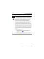
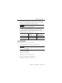
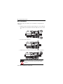
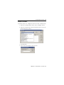
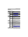
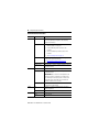
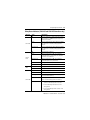
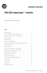
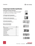
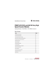
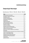
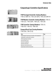
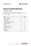
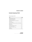
Installation Instructions
CompactLogix Controllers
Catalog Numbers 1768-L43, 1768-L43S, 1768-L45, 1768-L45S
Topic
Page
Important User Information
2
About CompactLogix Controllers
6
Verify Compatibility
6
Required System Components
7
Clearance Requirements
7
Module Placement
8
Install the Controller
9
Panel Mount the Controller
10
Mount the Controller on a DIN Rail
10
Confirm the Installation
13
Connect to the Controller
14
Configure a Communication Driver
14
Insert or Remove a CompactFlash Card
18
Install Controller Firmware
18
Remove a 1768 or 1769 Module from the DIN Rail
21
Status Indicators
23
Safety Status Indicators (1768-L43S and 1768-L45S Controllers only)
25
Clear a Major Fault
26
Clear a Nonrecoverable Fault
27
Troubleshoot a Nonresponsive Module
27
Troubleshoot System Power
28
Specifications
32
Additional Resources
36
2 CompactLogix Controllers
Important User Information
Solid state equipment has operational characteristics differing from those of electromechanical
equipment. Safety Guidelines for the Application, Installation and Maintenance of Solid State Controls
(publication SGI-1.1 available from your local Rockwell Automation sales office or online at
http://literature.rockwellautomation.com) describes some important differences between solid state
equipment and hard-wired electromechanical devices. Because of this difference, and also because of
the wide variety of uses for solid state equipment, all persons responsible for applying this equipment
must satisfy themselves that each intended application of this equipment is acceptable.
In no event will Rockwell Automation, Inc. be responsible or liable for indirect or consequential damages
resulting from the use or application of this equipment.
The examples and diagrams in this manual are included solely for illustrative purposes. Because of the
many variables and requirements associated with any particular installation, Rockwell Automation, Inc.
cannot assume responsibility or liability for actual use based on the examples and diagrams.
No patent liability is assumed by Rockwell Automation, Inc. with respect to use of information, circuits,
equipment, or software described in this manual.
Reproduction of the contents of this manual, in whole or in part, without written permission of Rockwell
Automation, Inc., is prohibited.
Throughout this manual, when necessary, we use notes to make you aware of safety considerations.
WARNING
IMPORTANT
ATTENTION
SHOCK HAZARD
BURN HAZARD
Identifies information about practices or circumstances that can cause an explosion in
a hazardous environment, which may lead to personal injury or death, property
damage, or economic loss.
Identifies information that is critical for successful application and understanding of
the product.
Identifies information about practices or circumstances that can lead to personal
injury or death, property damage, or economic loss. Attentions help you identify a
hazard, avoid a hazard and recognize the consequences.
Labels may be on or inside the equipment, for example, drive or motor, to alert people
that dangerous voltage may be present.
Labels may be on or inside the equipment, for example, drive or motor, to alert people
that surfaces may reach dangerous temperatures.
Publication 1768-IN004D-EN-P - December 2009
CompactLogix Controllers 3
Environment and Enclosure
ATTENTION
This equipment is intended for use in a Pollution Degree 2 industrial environment,
in overvoltage Category II applications (as defined in IEC publication 60664-1), at
altitudes up to 2000 m (6562 ft) without derating.
This equipment is considered Group 1, Class A industrial equipment according to
IEC/CISPR Publication 11. Without appropriate precautions, there may be
difficulties with electromagnetic compatibility in residential and other
environments due to conducted as well as radiated disturbances.
This equipment is supplied as open-type equipment. It must be mounted within
an enclosure that is suitably designed for those specific environmental
conditions that will be present and appropriately designed to prevent personal
injury resulting from accessibility to live parts. The enclosure must have suitable
flame-retardant properties to prevent or minimize the spread of flame, complying
with a flame spread rating of 5VA, V2, V1, V0 (or equivalent) if non-metallic. The
interior of the enclosure must be accessible only by the use of a tool. Subsequent
sections of this publication may contain additional information regarding specific
enclosure type ratings that are required to comply with certain product safety
certifications.
In addition to this publication, see:
• Industrial Automation Wiring and Grounding Guidelines, Rockwell
Automation publication 1770-4.1, for additional installation
requirements.
• NEMA Standards 250 and IEC 60529, as applicable, for explanations of
the degrees of protection provided by different types of enclosure.
Publication 1768-IN004D-EN-P - December 2009
4 CompactLogix Controllers
European Hazardous Location Approval
Consider the following if you install a 1768-L43S or 1768-L45S
controller in a European Zone 2 location.
European Zone 2 Certification (The following applies when the product bears the
EX marking.)
This equipment is intended for use in potentially explosive atmospheres as defined by
European Union Directive 94/9/EC and has been found to comply with the Essential Health
and Safety Requirements relating to the design and construction of Category 3 equipment
intended for use in Zone 2 potentially explosive atmospheres, given in Annex II to this
Directive.
Compliance with the Essential Health and Safety Requirements has been assured by
compliance with EN 60079-15 and EN 60079-0.
WARNING
• This equipment must be installed in an enclosure providing at least IP54
protection when applied in Zone 2 environments.
• This equipment shall be used within its specified ratings defined by
Allen-Bradley.
• Provision shall be made to prevent the rated voltage from being
exceeded by transient disturbances of more than 40% when applied in
Zone 2 environments.
• This equipment is not resistant to sunlight or other sources of UV
radiation.
• Secure any external connections that mate to this equipment by using
screws, sliding latches, threaded connectors, or other means provided
with this product.
• Do not disconnect equipment unless power has been removed or the
area is known to be nonhazardous.
General Safety Information for 1768-L43S and 1768-L45S Controllers
ATTENTION
Personnel responsible for the application of safety-related programmable
electronic systems (PES) shall be aware of the safety requirements in the
application of the system and shall be trained in using the system.
Publication 1768-IN004D-EN-P - December 2009
CompactLogix Controllers 5
North American Hazardous Location Approval
The following information applies when
operating this equipment in hazardous
locations.
Informations sur l’utilisation de cet
équipement en environnements dangereux.
Products marked "CL I, DIV 2, GP A, B, C, D" are suitable for
use in Class I Division 2 Groups A, B, C, D, Hazardous
Locations and nonhazardous locations only. Each product is
supplied with markings on the rating nameplate indicating
the hazardous location temperature code. When
combining products within a system, the most adverse
temperature code (lowest "T" number) may be used to help
determine the overall temperature code of the system.
Combinations of equipment in your system are subject to
investigation by the local Authority Having Jurisdiction at
the time of installation.
Les produits marqués "CL I, DIV 2, GP A, B, C, D" ne
conviennent qu'à une utilisation en environnements de
Classe I Division 2 Groupes A, B, C, D dangereux et non
dangereux. Chaque produit est livré avec des marquages sur
sa plaque d'identification qui indiquent le code de
température pour les environnements dangereux. Lorsque
plusieurs produits sont combinés dans un système, le code de
température le plus défavorable (code de température le plus
faible) peut être utilisé pour déterminer le code de
température global du système. Les combinaisons
d'équipements dans le système sont sujettes à inspection par
les autorités locales qualifiées au moment de l'installation.
WARNING
EXPLOSION HAZARD -
AVERTISSEMENT
• Do not disconnect equipment unless
power has been removed or the
area is known to be nonhazardous.
• Do not disconnect connections to
this equipment unless power has
been removed or the area is known
to be nonhazardous. Secure any
external connections that mate to
this equipment by using screws,
sliding latches, threaded
connectors, or other means
provided with this product.
• Substitution of components may
impair suitability for Class I,
Division 2.
• If this product contains batteries,
they must only be changed in an
area known to be nonhazardous.
RISQUE D’EXPLOSION –
• Couper le courant ou s'assurer
que l'environnement est classé
non dangereux avant de
débrancher l'équipement.
• Couper le courant ou s'assurer
que l'environnement est classé
non dangereux avant de
débrancher les connecteurs. Fixer
tous les connecteurs externes
reliés à cet équipement à l'aide
de vis, loquets coulissants,
connecteurs filetés ou autres
moyens fournis avec ce produit.
• La substitution de composants
peut rendre cet équipement
inadapté à une utilisation en
environnement de Classe I,
Division 2.
• S'assurer que l'environnement est
classé non dangereux avant de
changer les piles.
Preventing Electrostatic Discharge
ATTENTION
This equipment is sensitive to electrostatic discharge, which can cause internal
damage and affect normal operation. Follow these guidelines when you handle
this equipment:
• Touch a grounded object to discharge potential static.
• Wear an approved grounding wriststrap.
• Do not touch connectors or pins on component boards.
• Do not touch circuit components inside the equipment.
• Use a static-safe workstation, if available.
• Store the equipment in appropriate static-safe packaging when not in use.
Publication 1768-IN004D-EN-P - December 2009
6 CompactLogix Controllers
About CompactLogix Controllers
CompactLogix 1768-L43 and 1768-L45 controllers are designed to
provide a Logix solution for medium-sized applications. Compact
GuardLogix controller catalog numbers end in ‘S’. These safety
controllers are wider than their standard counterparts.
1768-L43, 1768-L45
1768-L43S, 1768-L45S
Verify Compatibility
IMPORTANT
Attempting to use controllers with incompatible software and firmware
revisions may result in:
• an inability to connect to the series B controller in RSLogix 5000
software.
• unsuccessful firmware upgrades in ControlFlash or AutoFlash
utilities.
This table shows the compatible RSLogix 5000 software versions and
controller firmware revisions.
Controllers
RSLogix 5000 Software
Version or Later
Controller Firmware
Revision or Later
1768-L43 and 1768-L45,
Series B
16.03
16.23
1768-L43S and 1768-L45S,
Series B
18
18
Publication 1768-IN004D-EN-P - December 2009
CompactLogix Controllers 7
Required System Components
You need these parts when installing your controller:
• 1768-L43, 1768-L43S, 1768-L45, or 1768-L45S CompactLogix
controller
• 1768-PA3 or 1768-PB3 power supply
• 1769-ECR end cap
• Mounting screws (M4 or #8 panhead) or one of these
EN 50 022 DIN rails:
– 35 x 7.5 mm (1.38 x 0.30 in.)
– 35 x 15 mm (1.38 x 0.59 in.)
• 1756-CP3 serial cable (or make your own)
Clearance Requirements
Allow for the minimum clearance from enclosure walls, wireways,
and other equipment.
105 mm (4.13 in.)
90 mm
(3.54 in.)
90 mm
(3.54 in.)
Power
OUT
L1
L2/N
31609-M
105 mm (4.13 in.)
IMPORTANT
These minimum clearances keep the modules cool enough in most situations.
See Specifications on page 32 for the acceptable temperature range.
Publication 1768-IN004D-EN-P - December 2009
8 CompactLogix Controllers
Module Placement
1768 Backplane (local)
1768 Controller, Power
Supply, and I/O Modules
Remote Bank
1769 Power Supply and
I/O Modules
1769 Backplane
IMPORTANT
CompactLogix System Distance Ratings
Because the 1768 CompactLogix power supply works with the controller to
power a 1768 system, the distance rating in a 1768 CompactLogix system differs
from that in a 1769 CompactLogix system.
In the 1768 system, the distance rating is the distance between 1769 I/O modules
and the controller. In the 1769 system, the distance rating is the distance
between 1769 I/O modules and the power supply.
Follow these requirements to determine proper placement of your
1768 controller, power supply, 1768 I/O modules, and 1769 I/O
modules:
• Place the 1768-L4xx controller so that it is the last module
(furthest away from the power supply) in the 1768 backplane.
• The 1768 CompactLogix power supply distributes power from
the right side of the supply and must be the leftmost module
in the system.
• Up to eight 1769 I/O modules can reside in the local bank.
• The local bank is powered by a 1768 power supply.
• Up to two remote banks of 1769 I/O modules may be
connected by using 1769-CRLx extension cables.
• Remote banks are powered by a standard 1769 power supply.
Publication 1768-IN004D-EN-P - December 2009
CompactLogix Controllers 9
• Up to eight 1769 Compact I/O modules can reside on each
side of a 1769 power supply in a remote bank. Consult the
module’s specifications for its distance rating.
IMPORTANT
Never place a 1769 power supply in a local bank with a 1768
controller or a major fault will occur.
• The type of controller determines the maximum number of
1768 modules that can reside in the local bank and the
maximum number of 1769 I/O modules that can reside in one
local and up to two remote banks.
Controller
Max Local 1768
Modules
Max 1769 I/O Modules
(local and remote)
1768-L43, 1768-L43S
2
16
1768-L45, 1768-L45S
4
30
Install the Controller
Follow these steps to install your controller.
1. Mount the controller to a panel or on a DIN rail.
IMPORTANT
Do not use screws if using a DIN rail to mount the controller. You can
break the mounting tabs if you screw the controller to a panel while it
is on a DIN rail.
2. Confirm the installation.
3. Connect the controller.
4. Configure a serial or Ethernet driver.
5. Install a CompactFlash card (optional).
6. Download and install controller firmware.
Publication 1768-IN004D-EN-P - December 2009
10 CompactLogix Controllers
Panel Mount the Controller
Follow these steps to mount your controller by using the panhead
screws.
1. Connect the CompactLogix modules together as shown in
Mount the Controller on a DIN Rail on page 10.
2. Use the controller as a template and mark pilot holes on your
panel.
3. Drill the pilot holes for M4 or #8 screws.
ATTENTION
During mounting of all devices, be sure that all debris (such as metal
chips or wire strands) is kept from falling into the controller or I/O
modules. Debris that falls into the controller or modules could cause
damage while the controller is energized.
4. Use M4 or #8 screws to mount the controller to your panel
with 1.16 N•m (10 lb•in) of torque.
5. Ground the module on a ground bus with a dedicated earth
ground stake.
6. Connect the ground bus to a functional earth ground on the
panel or a DIN rail.
Mount the Controller on a DIN Rail
ATTENTION
This product is grounded through the DIN rail to chassis ground. Use zinc
plated yellow-chromate steel DIN rail to assure proper grounding. The use of
other DIN rail materials (for example, aluminum and plastic) that can corrode,
oxidize, or are poor conductors, can result in improper or intermittent
grounding. Secure DIN rail to the mounting surface approximately every
200 mm (7.87 in.) and use end anchors appropriately.
Publication 1768-IN004D-EN-P - December 2009
CompactLogix Controllers 11
Mount 1768 Components
Follow these steps to mount the controller.
1. Mount the controller on the DIN rail.
a.
b.
31595-M
31596 -M
2. Mount additional 1768 modules to the left of the controller.
c.
a.
b.
a.
31597-M
c.
31598 -M
3. Mount the 1768 power supply and other 1768 modules.
31599-M
Publication 1768-IN004D-EN-P - December 2009
12 CompactLogix Controllers
Mount 1769 I/O Modules
Follow these steps to mount 1769 I/O modules to the right of the
controller.
1. Align the upper and lower tongue-and-groove slots and slide
the module back toward the DIN rail until the bus levers line
up.
2. Close the DIN rail latches.
3. Slide the bus lever to the left to lock the modules together.
ATTENTION
When attaching I/O modules, it is very important that the bus
connectors are securely locked together for proper electrical
connection.
Publication 1768-IN004D-EN-P - December 2009
CompactLogix Controllers 13
4. Attach the end cap by using the tongue and groove slots (a)
and locking the bus lever (b).
a.
b.
a.
Confirm the Installation
After you have installed the controller and applied power, check that
the PWR and I/O PWR status indicators are solid green.
Power
OUT
L1
L2/N
If the indicators are in any other state, see Troubleshoot System
Power on page 28.
Publication 1768-IN004D-EN-P - December 2009
14 CompactLogix Controllers
Connect to the Controller
WARNING
If you connect or disconnect the serial cable with power applied to this module
or the serial device on the other end of the cable, an electrical arc can occur. This
could cause an explosion in hazardous location installations.
Be sure that power is removed or the area is nonhazardous before proceeding.
Connect the 1756-CP3 serial cable to the controller’s serial port and to
your workstation.
If you make your own cable, follow these guidelines.
• Wire the connectors as
shown.
• Limit the cable length
to 15.2 m (50 ft).
• Attach the shield to
both connectors.
Workstation
Controller
1 DCD
2 RDX
3 TXD
4 DTR
COMMON
6 DSR
7 RTS
8 CTS
9
1 DCD
2 RDX
3 TXD
4 DTR
COMMON
6 DSR
7 RTS
8 CTS
9
Configure a Communication Driver
Before you update controller firmware or use the controller in your
network, you must configure a communication driver specific to your
network.
See Configure a Serial Driver on page 15 or Configure an EtherNet/IP
Driver on page 17.
Publication 1768-IN004D-EN-P - December 2009
CompactLogix Controllers 15
Configure a Serial Driver
Use RSLinx software to configure the driver for serial communication.
1. From the Communications menu, choose Configure Drivers.
2. From the Available Driver Types pull-down menu, choose the
RS-232 DF1 devices driver.
3. Click Add New.
4. Type a name for the driver and click OK.
Publication 1768-IN004D-EN-P - December 2009
16 CompactLogix Controllers
5. From the Comm Port pull-down menu on the Configure
Devices dialog box, choose the serial port on the workstation
to which your cable is connected.
6. From the Device pull-down menu, choose
Logix5550/CompactLogix.
7. Click Auto-Configure.
a. Click OK if the Auto Configuration Successful dialog box
appears.
b. If the dialog box does not appear, go back to step 5 and
verify that you selected the correct comm port.
8. Click Close.
Publication 1768-IN004D-EN-P - December 2009
CompactLogix Controllers 17
Configure an EtherNet/IP Driver
For EtherNet/IP communication, you must use a 1768-ENBT or
1768-EWEB module. If your controller is a 1768-L4xS, you must use a
series B 1768-ENBT or 1768-EWEB module. You can install up to two
of these modules to the left of the controller in the 1768 backplane.
Before you can load controller firmware via the EtherNet/IP network,
you must set the EtherNet/IP module’s IP address. You can set the IP
address by using the BootP-DHCP Utility on the Tools menu in
RSLogix 5000 software.
For more information, refer to the EtherNet/IP Modules in Logix5000
Control Systems User Manual, publication ENET-UM001.
Set the Communication Path to the Controller
1. Open an RSLogix 5000 project for the controller.
2. From the Communications menu, choose Who Active.
3. Expand the communication driver to the level of the
controller.
4. Select the controller.
5. Complete the desired action.
To
Click
Monitor the project in the controller
Go Online
Transfer a copy of the project from the controller to RSLogix 5000 software
Upload
Transfer the open project to the controller
Download
Publication 1768-IN004D-EN-P - December 2009
18 CompactLogix Controllers
Insert or Remove a CompactFlash Card
WARNING
When you insert or remove the CompactFlash card while power is on, an
electrical arc can occur. This could cause an explosion in hazardous location
installations.
Be sure that power is removed or the area is nonhazardous before proceeding.
Follow these steps to insert or remove a
CompactFlash card.
1. Press the memory-card door latch on the
controller front panel and pivot the door
down toward you.
2. Insert or remove the card from the slot.
3. Close the memory card door.
Install Controller Firmware
The controller ships without functioning firmware, so you must
obtain and install the firmware before you can use your controller.
IMPORTANT
When installing or updating controller firmware, do not interrupt the update
process in any way. Interrupting the firmware update may result in an
inoperable controller.
Inoperable controllers must be returned to Rockwell Automation.
Firmware revisions are available with RSLogix 5000 programming
software, or you can download them from the support website at:
http://support.rockwellautomation.com. Be prepared to enter the
serial number of your RSLogix 5000 software.
To install firmware, you can use any of the following.
Method
Page
ControlFlash, version 8 or later, software that ships with RSLogix 5000 software
19
AutoFlash software that runs within RSLogix 5000 software
20
A 1784-CF64 or 1784-CF128 CompactFlash card with valid firmware already loaded 21
Publication 1768-IN004D-EN-P - December 2009
CompactLogix Controllers 19
Updating your controller firmware via ControlFlash or AutoFlash
software requires either a serial or other network connection to the
controller.
Updating via an Ethernet connection is faster, but you must first
install a 1768-ENBT Ethernet module to connect to the controller via
the Ethernet network.
For information on installing, configuring, and operating a
1768-ENBT module, refer to the EtherNet/IP Modules in Logix5000
Control Systems User Manual, publication ENET-UM001.
Install Firmware via ControlFlash Software
1. Make sure the network is connected.
2. Start ControlFlash software.
3. When the Welcome dialog box appears, click Next.
4. Select the catalog number of the controller and click Next.
5. Expand the network until you see the controller.
TIP
If the required network is not shown, first configure a driver for that
network in RSLinx software.
6. Select the controller and click OK.
7. Select the desired revision level and click Next.
8. To start the update, click Finish and then Yes.
The OK status indicator flashes red to show that the update is
in progress. The status box indicates when the update is
complete and the OK status indicator is solid green.
9. Click OK.
10. Click Cancel and then Yes to close ControlFlash software.
Publication 1768-IN004D-EN-P - December 2009
20 CompactLogix Controllers
Install Firmware via AutoFlash Software
1. Make sure the network is connected.
2. Using RSLogix 5000 software, attempt a download to a
controller project.
AutoFlash software launches if the required firmware is not
loaded on the controller.
3. Select the catalog number of the controller and click Next.
4. Expand the network until you see the controller.
TIP
If the required network is not shown, first configure a driver for that
network in RSLinx software.
5. Select the controller and click OK.
6. Select the desired revision level and click Next.
7. To start the update, click Finish and then Yes.
The OK status indicator flashes red to show that the update is
in progress. The status box indicates when the update is
complete and the OK status indicator is solid green.
8. Click OK.
9. Click Cancel and then Yes to close AutoFlash software.
Publication 1768-IN004D-EN-P - December 2009
CompactLogix Controllers 21
Install Firmware via a CompactFlash Card
Follow these steps to use RSLogix 5000 software to store the
controller program and firmware of an already-configured controller
to the CompactFlash card. The firmware is automatically stored on
your CompactFlash card when you store the program.
1. With the CompactFlash card installed on the configured
controller, on the Controller Properties dialog box, click the
Nonvolatile Memory tab.
2. Click Load Image On Powerup to save to the card.
3. Remove the card and insert it into the controller onto which
you want to load the firmware and user program.
4. Start the new controller and the image stored on the
CompactFlash card loads.
Remove a 1768 or 1769 Module from the DIN Rail
If you need to remove a module from the DIN rail, follow these steps.
1. Remove power from the controller and wait for all status
indicators on the power supply and controller to turn off.
Off
Power
OUT
L1
L2/N
IMPORTANT
If you disconnect any part of the system while the controller is still writing its
program to memory, you will lose your program.
Publication 1768-IN004D-EN-P - December 2009
22 CompactLogix Controllers
2. Remove the 1768 module.
a.
b.
Power
OUT
L1
L2/N
a.
d.
c.
Power
O UT
L1
L 2 /N
c.
31607-M
3. Remove the 1769 module by unlocking the bus lever (a) and
DIN rail latches (b).
b.
a.
Power
OUT
L1
L2/N
b.
4. Slide the module away from the DIN rail along the tongue and
groove slots.
Publication 1768-IN004D-EN-P - December 2009
CompactLogix Controllers 23
Status Indicators
Controller Status Indicators
Indicator
State
Description
Green
The controller is providing power to 1768 modules in
the system.
PWR
I/O PWR
RUN
FORCE
MEM
SAVE
I/O
Off or red
See Troubleshoot System Power on page 28.
Off
Replace the controller.
Green
The controller is operating properly.
Flashing red/green
or solid red
See Troubleshoot System Power on page 28.
Off
The controller is in PROG or Test mode.
Green
The controller is in RUN mode.
Off
No tags contain I/O force values or I/O forces are
inactive (disabled).
Amber
I/O forces are active (enabled). I/O force values may or
may not exist.
Flashing amber
One or more input or output addresses have been
forced to an On or Off state, but the forces have not
been enabled. Enable forces or remove the individual
I/O from being forced.
Off
The user program and configuration data are not
actively being saved to flash memory.
Green
The use program and configuration data are being
saved to flash memory.
Off
There are no devices in the I/O configuration of the
controller or the controller does not contain a project.
Green
The controller is communicating with all of the devices
in its I/O configuration.
Flashing green
One or more devices in the controller’s I/O configuration
are not responding.
See Troubleshoot a Nonresponsive Module on page 27.
Flashing red
The controller is not communicating with any of the
devices in its I/O configuration.
See Troubleshoot a Nonresponsive Module on page 27.
Publication 1768-IN004D-EN-P - December 2009
24 CompactLogix Controllers
Controller Status Indicators
Indicator
State
Description
OK
Off
No power is applied. If MEM SAVE indicator is green,
the user program and configuration data are being
saved to flash memory.
Flashing red
• The controller requires a firmware update or a
firmware update is in progress.
• A recoverable major fault occurred on the
controller.
• A nonrecoverable major fault occurred on the
controller.
• See Clear a Major Fault on page 26.
CF
Red
The controller detected a nonrecoverable major fault so
it cleared the project from memory.
See Clear a Nonrecoverable Fault on page 27.
Green
Controller is OK.
Flashing green
The controller is storing or loading a project to or from
nonvolatile memory.
Off
There is no CompactFlash card activity.
Flashing green
The controller is reading from or writing to the
CompactFlash card.
IMPORTANT: Do not remove the CompactFlash card
while the controller is reading from or writing to the
card. Removing the card during a read or write could
corrupt data on the card, data in the controller, and
firmware installed on the controller.
Flashing red
The CompactFlash card does not have a valid file
system and must be replaced.
DCH0
Off
Channel 0 is configured differently than the default
serial configuration.
Green
Channel 0 has the default serial configuration.
CH0
Off
No RS-232 activity.
Green
RS-232 activity.
Publication 1768-IN004D-EN-P - December 2009
CompactLogix Controllers 25
Safety Status Indicators (1768-L43S and 1768-L45S Controllers only)
Indicator
State
Description
Off
The user safety task or safety outputs are disabled.
The controller is in PROG mode, Test mode, or the
safety task is faulted.
Green
The user safety task and safety outputs are enabled.
The safety task is executing. Safety signature is
present.
Flashing green
The user safety task and safety outputs are enabled.
The safety task is executing. Safety signature is not
present.
Off
No partnership established.
Green
Safety controller status is OK. The coordinated
system time (CST) is synchronized and safety I/O
connections are established.
Flashing green
Safety controller status is OK. The coordinated
system time (CST) is not synchronized.
SAFE RUN
SAFETY
TASK
SAFETY
LOCK
Red
Safety partnership was lost.
Flashing red
Safety task is inoperable.
Off
Safety task is not locked.
Green
Safety task is locked.
Off
No power is applied.
Green
The safety partner is OK.
Flashing green
The safety partner is storing or loading a project to
or from nonvolatile memory.
Red
The safety partner detected a nonrecoverable major
fault, so it cleared the project from its memory.
SAFETY OK
Flashing red
• The internal safety partner requires a firmware
update or a firmware update is in progress.
• A recoverable major fault occurred on the
safety partner.
• A nonrecoverable major fault occurred on the
safety partner.
Publication 1768-IN004D-EN-P - December 2009
26 CompactLogix Controllers
Clear a Major Fault
If the OK status indicator flashes red because of a recoverable major
fault, clear the fault by following these steps.
1. Turn the controller keyswitch from PROG to RUN and back to
PROG.
2. Go online with RSLogix 5000 software.
3. On the Controller Properties dialog box, click the Major Faults
tab to find information about the fault.
If the OK status indicator is flashing red because of a nonrecoverable
major fault, the controller:
•
•
•
•
•
initially displayed a solid red OK indicator.
reset itself.
cleared the project from its memory.
set the OK indicator to flashing red.
produced a major recoverable fault and generated a
corresponding fault code in the RSLogix 5000 project.
– Fault code 60 means the CompactFlash card is not installed.
– Fault code 61 means the CompactFlash card is installed.
Follow these steps to recover from fault code 60 or 61.
1. Turn the controller keyswitch from PROG to RUN and back to
PROG.
2. Go online with RSLogix 5000 and download the project.
3. Change to REM RUN or RUN mode.
If the issue persists, record the status of the OK and RS-232 indicators
before cycling power and contacting Rockwell Automation support.
Publication 1768-IN004D-EN-P - December 2009
CompactLogix Controllers 27
Clear a Nonrecoverable Fault
If the OK status indicator is solid red, follow these steps to clear the
fault.
1. Cycle power.
2. Download the project.
3. Change to REM RUN or RUN mode.
If the issue persists, record the status of the OK and RS-232 indicators
before cycling power and contacting Rockwell Automation support.
Troubleshoot a Nonresponsive Module
Follow these steps to determine why a device may not be
responding.
1. Verify that all I/O modules in your project are installed in the
same order.
2. Verify that all devices have been updated to the latest major
and minor firmware revisions.
3. Use RSLogix 5000 software’s online help to determine which
module is not responding.
Publication 1768-IN004D-EN-P - December 2009
28 CompactLogix Controllers
Troubleshoot System Power
The CompactLogix power supply works with the CompactLogix
controller to provide power to the system. You must consider both
when attempting to troubleshoot system power.
IMPORTANT
Before you disconnect, reconnect, or replace any component, make sure you
have turned off power and allowed all system status indicators to turn off.
To troubleshoot system power issues, use the CompactLogix power
supply PWR status indicator and the CompactLogix controller PWR
and I/O PWR indicators. If the power supply is not operating
properly, the controller will not operate properly either. You must
first diagnose and correct any issues with the power supply before
troubleshooting the controller.
1. Examine the power supply PWR status indicator.
2. If the power supply is operating properly and the power
supply PWR status indicator is green, examine the controller
PWR indicator.
3. If the controller PWR status indicator is green, examine the I/O
PWR status indicator.
Publication 1768-IN004D-EN-P - December 2009
CompactLogix Controllers 29
Examine the Power Supply PWR Status Indicator
Power Supply PWR
Indicator Status
Recommended Action
Off
Verify that the power supply is turned on and that adequate input
power is properly connected.
Replace the power supply.
Green
The power supply is operating properly.
Check the controller PWR and I/O PWR status indicators to make
sure the entire system is operating properly.
Red
The power supply is not producing valid 24V power to the 1768
modules. Follow the corrective action below.
1. Remove power and wait for all status indicators to turn off.
2. Disconnect all modules from the system, including the
controller.
3. Reapply power.
4. Check the PWR status indicator on the power supply.
a. If the status indicator remains red, replace the power
supply.
b. If the status indicator is green, one of the other modules in
the system is causing the red indicator.
5. Remove power and wait for all status indicators to turn off.
6. Reinstall the controller and check the power supply’s PWR
indicator.
a. If green, remove power, wait for all status indicators to turn
off and reinstall 1768 modules one at a time until you
identify the module causing the red indicator.
b. If red, replace the controller.
Publication 1768-IN004D-EN-P - December 2009
30 CompactLogix Controllers
Examine the Controller PWR Indicator
This task assumes that the power supply PWR indicator is green.
Controller PWR Indicator
Status
Recommended Action
Off
Make sure all of the modules in the system are installed
properly and are fully engaged with one another. If the
indicator remains off, follow the corrective action below.
Green
The controller is providing power to 1768 modules in the
system.
Check the controller I/O PWR status indicator to make sure
the entire system is operating properly.
Red
Either the controller or 1768 modules in the system need to
be replaced. Follow the corrective action below.
1. Remove power and wait for all status indicators to turn off.
2. Disconnect all 1768 modules from the system, except for the
controller.
3. Reapply power.
4. Check the controller PWR indicator.
a. If the status indicator remains red, replace the controller.
b. If the status indicator is green, one of the 1768 modules is
causing the red indicator.
5. Remove power.
6. Reinstall the 1768 modules one at a time, removing and
reapplying power and checking the controller PWR indicator
each time.
7. If the controller PWR indicator turns red, the most-recently
installed module is causing the red indicator.
To troubleshoot 1768 modules, see their respective installation
instructions.
Publication 1768-IN004D-EN-P - December 2009
CompactLogix Controllers 31
Examine the I/O PWR Indicator
This task assumes that the power supply and controller PWR
indicators are green and that you have 1769 I/O modules in your
system.
Controller I/O PWR
Recommended Action
Indicator Status(1)
Off
Replace the controller.
Green
The controller is operating properly. No action required.
Flashing red and green
Make sure the 1769 I/O modules or end cap are properly
attached and cycle power.
Red
A 1769 power supply may be installed in the local bank, or
there may be an issue with the controller or 1769 I/O in the
system. Follow the corrective action below.
(1)
When the controller powers up, the I/O PWR status indicator is momentarily red and then changes to
green if there are no issues. If the indicator remains red, use the table above to troubleshoot the issue.
1. If there is a 1769 power supply installed in the local bank,
remove it and reapply power.
If the I/O PWR indicator remains red, go to the next step.
2. Remove power and wait for all status indicators to turn off.
3. Disconnect the 1769 I/O modules from the system.
4. Reapply power.
5. Check the controller I/O PWR indicator.
a. If the indicator is red, replace the controller.
b. If the indicator is green, one of the 1769 I/O modules is
causing the red indicator.
To troubleshoot 1769 I/O modules, see their respective
installation instructions.
Publication 1768-IN004D-EN-P - December 2009
32 CompactLogix Controllers
Specifications
1768-L43, 1768-L43S, 1768-L45, 1768-L45S Controllers
Attribute
1768-L43
1768-L43S
1768-L45
1768-L45S
1768 backplane module
support
2
Backplane current
1.3 A @ 24V
1769 backplane current
output
2.0 A @ 5.2V
2.0 A @ 5.2V
1768 backplane current
output
2.8 A @ 5.2V
5.6 A @ 5.2V
Total 1768 and 1769
backplane current output
4.8 A @ 5.2V
7.6 A @ 5.2V
Power dissipation
6.3 W(2)
7.5 W(2)
8.3 W(2)
9.5 W(2)
Power consumption
31.3 W
33.6 W
48.0 W
50.4 W
Number of 1769-series I/O
modules, max
16
4
1.4 A @ 24V
2.0 A @ 24V
2.1 A @ 24V
30
Number of I/O banks, max
2
3
Number of 1768 modules
available, max
2(3)
4 (3)
Isolation voltage
30V (continuous)
Functional Insulation Type
Type Tested @ 500V AC for 60 s, RS-232 to system
Wiring category(1)
2 - on communication ports
North American
temperature code
T4
IEC temperature code
Not
Applicable
Mounting screw torque
1.16 N•m (10 lb•in), using M4 or #8 screws
T4
Publication 1768-IN004D-EN-P - December 2009
Not
Applicable
T4
CompactLogix Controllers 33
1768-L43, 1768-L43S, 1768-L45, 1768-L45S Controllers
Attribute
1768-L43
1768-L43S
1768-L45
1768-L45S
Dimensions (HxWxD),
approx.
131.6 x 67.4
x 121.8 mm
(5.18 x 2.65
x 4.80 in.)
131.6 x 90 x
121.8 mm
(5.18 x 3.55
x 4.80 in.)
131.6 x 67.4
x 121.8 mm
(5.18 x 2.65 x
4.80 in.)
131.6 x 90 x
121.8 mm
(5.18 x 3.55
x 4.80 in.)
Weight, approx.
0.34 kg
(11.9 oz)
0.45 kg (15.9
oz)
0.34 kg
(11.9 oz)
0.45 kg
(15.9 oz)
Enclosure type rating
None (open style)
(1)
(2)
(3)
Use this Conductor Category information for planning conductor routing. Refer to Industrial
Automation Wiring and Grounding Guidelines, publication 1770-4.1.
See related Power Dissipation chart that follows.
Important: You can have any combination of motion and network modules installed in a system.
There is a maximum limit of two network modules that can be installed in a system. Network
modules include: 1768-ENBT, 1768-CNB, 1768-CNBR, and 1768-EWEB.
1768-L43 and 1768-L43S Power Dissipation
7.5 W
8
Power
Dissipated
(Watts)
4.0 W
6
6.3 W
4
2.8 W
2
0
5
10
15
20
25
1768-L43S
1768-L43
30
1768 and 1769 Bus 5.2V Load (Watts)
Publication 1768-IN004D-EN-P - December 2009
34 CompactLogix Controllers
1768-L45 and 1768-L45S Power Dissipation
9.5 W
4.0 W
Power
Dissipated
(Watts)
2.8 W
8
8.3 W
6
4
1768-L45S
2
0
1768-L45
5
10
15
20
25
30
35
40
1768 and 1769 Bus 5.2V Load (Watts)
Environmental Specifications
Attribute
Value
Temperature,
operating
IEC 60068-2-1 (Test Ad, Operating Cold),
IEC 60068-2-2 (Test Bd, Operating Dry Heat),
IEC 60068-2-14 (Test Nb, Operating Thermal Shock):
0...60 °C (32...140 °F)
Temperature,
nonoperating
IEC 60068-2-1 (Test Ab, Unpackaged Nonoperating Cold),
IEC 60068-2-2 (Test Bb, Unpackaged Nonoperating Dry Heat),
IEC 60068-2-14 (Test Na, Unpackaged Nonoperating Thermal
Shock):
-40...85 °C (-40...185 °F)
Relative humidity
IEC 60068-2-30 (Test Db, Unpackaged Nonoperating Damp Heat):
5...95% noncondensing
Vibration
IEC 60068-2-6 (Test Fc, Operating):
5 g @ 10...500 Hz
Shock, operating
IEC 60068-2-27 (Test Ea, Unpackaged Shock): 30 g
Shock, nonoperating
IEC 60068-2-27 (Test Ea, Unpackaged Shock): 50 g
Emissions
CISPR 11: Group 1, Class A
ESD immunity
IEC 61000-4-2: 6 kV contact discharges
8 kV air discharges
EFT/B immunity
IEC 61000-4-4:
±4 kV at 5 kHz on communication ports
Publication 1768-IN004D-EN-P - December 2009
CompactLogix Controllers 35
Environmental Specifications
Attribute
Value
Radiated RF immunity
IEC 61000-4-3:
10V/m with 1 kHz sine-wave 80% AM from 80…2000 MHz
10V/m with 200 Hz 50% Pulse 100% AM @ 900 MHz
10V/m with 200 Hz 50% Pulse 100% AM @ 1890 MHz
3V/m with 1 kHz sine-wave 80% AM from 2000…2700 MHz
Surge transient
immunity
IEC 61000-4-5:
±2 kV line-earth (CM) on communication ports
Conducted RF
immunity
IEC 61000-4-6:
10V rms with 1 kHz sine-wave 80%AM from 150 kHz…80 MHz
Certifications (when product is marked)(1)
Certification
Value
c-UL-us
UL Listed Industrial Control Equipment, certified for US and Canada. See
UL File E65584.
UL Listed for Class I, Division 2 Group A,B,C,D Hazardous Locations,
certified for U.S. and Canada. See UL File E194810.
CE
European Union 2004/108/EC EMC Directive, compliant with:
EN 61326-1; Meas./Control/Lab., Industrial Requirements
EN 61000-6-2; Industrial Immunity
EN 61000-6-4; Industrial Emissions
EN 61131-2; Programmable Controllers (Clause 8, Zone A & B)
C-Tick
Australian Radiocommunications Act, compliant with:
AS/NZS CISPR 11; Industrial Emissions
Ex
1768-L43S and 1768-L45S only:
European Union 94/9/EC ATEX Directive, compliant with:
EN 60079-15; Potentially Explosive Atmospheres, Protection ‘n’
II 3 G Ex nA IIC T4 X
EN60079-0; General Requirements
Functional
1768-L43S and 1768-L45S only:
Certified by TÜV: capable of SIL 1 to 3, according to IEC 61508; and
PLe/Cat. 4 according to ISO 13849-1
Safety(2)
(1)
(2)
See the Product Certifications link at www.ab.com for Declarations of Conformity, certificates, and
other certification details.
When used with specified software versions.
Publication 1768-IN004D-EN-P - December 2009
Additional Resources
These documents contain additional information concerning related
Rockwell Automation http://www.ab.com products.
Resource
Description
EtherNet/IP Modules in Logix5000 Control
Systems User Manual, publication
ENET-UM001
Details how to configure, program, operate,
and troubleshoot EtherNet/IP modules, and
provides technical specifications.
1768 CompactLogix Controllers User
Manual, publication 1768-UM001
Details how to configure, program, and
operate a 1768 CompactLogix system, and
provides technical specifications.
Compact GuardLogix Controllers User
Manual, publication 1768-UM002
Details how to configure, program, and
operate a 1768 Compact GuardLogix
system.
GuardLogix Controller Systems Safety
Reference Manual, publication 1756-RM093
Information on the safety requirements for
GuardLogix controller systems.
Industrial Automation Wiring and Grounding
Guidelines, publication 1770-4.1
Provides general guidelines for installing a
Rockwell Automation industrial system.
Product Certifications website,
http://www.ab.com
Provides declarations of conformity,
certificates, and other certification details.
You can view or download publications at
http://literature.rockwellautomation.com. To order paper copies of
technical documentation, contact your local Rockwell Automation
distributor or sales representative.
Allen-Bradley, Rockwell Automation, Rockwell Software, CompactLogix, GuardLogix, RSLogix 5000,
ControlFlash, RSLinx, Logix5000, and TechConnect are trademarks of Rockwell Automation, Inc.
Trademarks not belonging to Rockwell Automation are property of their respective companies.
Publication 1768-IN004D-EN-P - December 2009
Supersedes Publication 1768-IN004C-EN-P - October 2008
PN-48443
Copyright © 2009 Rockwell Automation, Inc. All rights reserved. Printed in the U.S.A.