1
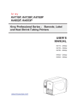
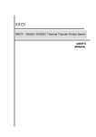
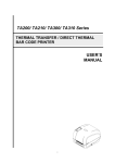
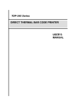
KROY K4652/K4653
THERMAL TRANSFER / DIRECT THERMAL
BAR CODE PRINTER
USER’S MANUAL
CONTENTS
1. PRODUCT INTRODUCTION .............................................….…….. 1
1.1 Compliances.....................................................................………… 1
1.2 Specification .....................................................................….…….. 1
1.2.1 Printer ............................................................................…….. 1
1.2.2 Environment....................................................................…….. 2
1.2.3 Hardware.........................................................................….. ... 2
1.2.4 Bar Code.........................................................................…….. 2
1.3 Optional Items ......................................................................…….. 3
1.4 Supplies.................................................................................…….. 3
1.4.1 Label Specification .........................................................…….. 3
1.4.2 Ribbon Specification.....................................................……… 3
2. GETTING STARTED ................….............................................….. 4
2.1 Unpacking and Inspection..................................................……. 4
2.2 Equipment Checklist ..........................................................……. 4
2.3 Printer Parts ......................................................................…….. 5
2.4 Buttons and Indicators ......................................................…….. 6
3. Set Up…..................................................................…………...…… 8
3.1 Setting Up the Printer ........................................................……. 8
3.2 Ribbon Installation…..........................................................……. 8
3.3 Label Roll Installation ........................................................…….. 9
3.4 Cutter Module Installation.................................................….….. 10
3.5 Self-test ...........................................................................……... 11
3.6 Dump Mode.......................................................................…….. 12
4. USING THE K4652/K4653.............................……..................…….. 14
4.1 Power-on Utilities .............................................................……… 14
4.1.1 Gap/Black Mark Sensor Calibration Utility.................……… 14
4.1.2 Printer Initialisation ..................…..............................……… 15
4.2 Troubleshooting Guide.....................................................……... 17
5. PRINTER CLEANING …………..........................................…….. .. 19
5.1 Cleaning the Print Head ...................................................……… 19
5.2 Cleaning the Printer Cover ...............................................………19
5.3 Cleaning the Internal Parts................................................……... 19
APPENDIX LCD Control Panel Operation Map.........………. 20
Update History..….......................................................... …… 22
i
1. PRODUCT INTRODUCTION
Thank you very much for purchasing the KROY K4652/K4653 bar code printer. The printer
comes with a rugged steel construction and durable metal mechanism ensuring the ability to
work under extreme industrial applications.
The K4652/4653 is equipped with a 32-bit RISC processor, which offers a print speed of up
to 6 ips/4 ips. With a back-lit LCD display, the printer status can be managed more easily
and operated in a more user friendly manner. The moveable sensor design can handle a
wide range of label media.
All of the most frequently used bar code formats are available with the printer Fonts and bar
codes can be printed in any one of four directions. This printer provides a choice of 8
different sizes of alphanumeric font, OCR-A, OCR-B and one true type font. The
K4652/K4653 is the most cost-effective and high performance printer in its class!
1.1 Compliances
1.2 Specification
1.2.1 Printer
Specification
Item
Printing Mode
Thermal transfer and direct thermal
Resolution
203DPI (K4652), 300 DPI (K4653)
Max. Print Length
1000 mm (K4652), 460 mm (K4653)
Max. Print Width
108 mm (K4652), 106 mm (K4653)
Print Speed
3,4,5,6 ips K4652); 2,3,4 ips (K4653)
1
1.2.2 Environment
Operating Environment
Temperature
5 ~40 ºC
Humidity
30 % ~ 85 %
Storage Environment
Temperature
-10 ~ 60 ºC
Humidity
20 ~ 95 %
Ventilation
Free air environment
1.2.3 Hardware
Label gap sensor, Paper end sensor, Ribbon end sensor,
Ribbon near end sensor, Black mark sensor, Head open
Sensors
sensor, Case open sensor, Label taken sensor, Paper near
end sensor.
Flash ROM (2MB), DRAM (2MB) and 8M optional
Memory
flash ROM (memory module).
Interface
RS-232C (RS422/485 option), Centronics (SPP), USBV1.1
(Option) and Internal LAN adapter (option)
Cutter
4 inch width (Paper thickness up to 0.28 mm).
Power
100-240 V universal switching power supply.
Other
Real Time Clock (option).
1.2.4 Bar Code
Code 39, Code 39C, Code 93, Code128 subsets A.B.C, Code 11, Codabar,
Interleave 2 of 5, EAN-8, EAN-13, EAN-128, UPC-A, UPC-E, EAN and UPC
2(5) digital add-on, ISBT 128, LOGMARS, CPOST, MSI, PLESSEY, POSTNET,
ITF-14, PDF-417, Maxicode, DataMatrix.
2
1.3 Optional Items
Cutter module
Peel off sensor
Portable LCD keyboard (KU-007 plus)
Memory module
USB, RS-422/485 interfaces,
Internal Ethernet print server
802.11b wireless print server
1.4 Supplies
1.4.1 Label Specification
Item
Specification
Type
Roll and label (Continuous, die-cut, fan-fold, ticket, Tag etc.,
Tag is option)
Label Width
25.4 ~116 mm (1”~4.4”)
Label Length
10 ~999 mm (0.4”~39.33”)
Label Thickness
0.06 ~0.25 mm
Label Roll Diameter
203 mm (Max.)
Roll Core Diameter
25 or 77 mm
Black Mark Width
3 mm (Min.)
1.4.2 Ribbon Specification
Item
Specification
Ribbon Width
25.4 ~114.3 mm
Ribbon Length
300 m (Max.)
3
2. GETTING STARTED
2.1 Unpacking and Inspection
After receiving the bar code printer, carefully inspect the device and its packaging.
The printer is specially packaged to withstand damage in shipping. In case of
evident damage, contact the carrier directly to specify the nature and extent of
the damage. Please retain the packaging materials in case you need to reship the
printer.
2.2 Equipment Checklist
Printer unit
Ribbon paper core
Quick installation guide
Power cord
Centronics interface cable
3” paper core adapter
Label spindle fixing tab
Software CD
Separately purchased items may also be included. These additional items may
include:
Cutter module
Peel off sensor
KU-007 plus portable LCD keyboard
Memory module
USB, RS-422/485 interfaces
Internal Ethernet print server
802.11b wireless print server
If any part is missing, please contact the Customer Service Department of your
reseller or distributor where you purchased the printer.
4
2.3 Printer Parts
Aux. LED
Printer Right
Hand Cover
LCD Display
Figure 1. Top front view
External Label
Feed Opening
Centronics Port
RS-232C Port
Voltage Switch
Power Supply
Connector
Figure 2. Printer rear view
5
Ribbon Supply Spindle
Ribbon Tension Knob
Ribbon Rewind Spindle
Label Spindle
Media Guide Bar
Print Head Pressure
Adjustment Knob
Label Guide
Print Head Lift Lever
Figure 3. Printer interior view
2.4 Buttons and Indicators
Power Indicator
When the printer is in the power-on condition, the Power indicator is lit.
On-Line Indicator
This green On-Line indicator is lit when the printer is ready; the On-Line indicator blinks
when the PAUSE button is pressed.
Error Indicator
The red Error indicator illuminates in the event of a printer error, such as memory full,
carriage open, cutter error and so forth.
MENU/SELECT Button
The printer, which is provided with a built-in menu, allows the user to directly set printing
parameters or view the printer status on the LCD display.
Press the MENU button to enter printer setup mode. Press the MENU button again to move
the cursor to the next option.
The setup is comprised of the following main operations: Printer Setup, Sensor Setup,
System Setup, File Setup and Printer Test. For more information, please refer to the
Appendix for the structure and operation logic of the menu.
6
PAUSE/EXE/INC Button
This button enables three functions to be carried out:
A. If the printer status is Ready the PAUSE button may be used . By pressing the PAUSE
button: (1) the printer stops after printing the current label, (2) the On-Line LED
flashes, and (3) the printer holds all of the data in its memory. This allows for troublefree replacement of the label stock and thermal transfer ribbon. A second depression
of the PAUSE button will restart the printer.
B. If the printer is in setup mode the EXE/INC button may be used. Press the EXE/INC
button to increase the value of the parameters, or execute the selected item.
FEED/DEC Button
This button also has dual functions: It feeds one label and decreases the value of
the parameters.
Press the FEED button and the printer will advance one label.
Press the DEC button to change the parameter settings or exit the submenu.
Print Head Lift Lever
When disengaging the Print Head Lift Lever, the On-Line LED goes out and the LCD
display shows “Carriage Open”. After engaging the print head lift lever, press the
FEED button, the printer will re-register the label and then show READY on the LCD
display, and the screen will return to the ready condition.
Print Head Pressure Adjustment Knob
This is used to adjust the pressure of the print head. Please adjust the knob to the
proper setting to get the best print quality.There are 5 levels for the print head
pressure knobs. Some paper material does not allow very good printing, so you may
need to improve the printing quality by increasing the print head pressure. If the label
width is 4”, adjust both the print head pressure adjustment knobs to the same
pressure level. If the label width is 2” or less than 2”, adjust the left hand print head
pressure adjustment knob and release the right hand pressure knob to level 1.
Ribbon Tension Knob
There are 6 levels for the ribbon tension knob, which prevents the printing
ribbon from wrinkling when it is stretched. Turn the ribbon tension knob clockwise and
you will hear a slight clicking sound as the gear changes. The ribbon tension level
varies from loose to tight, level 1 to level 6. You will hear a big click for level 1.
7
3. Set Up
3.1 Setting Up the Printer
1.
Place the printer on a flat, secure surface.
2.
Make sure the POWER switch is off.
3.
Connect the printer to the computer with the RS-232C or Centronics cable
provided.
4.
Plug the power cord into the power supply connector at the rear of the
printer, and then plug the power cord into a properly grounded power point.
3.2 Ribbon Installation
1.
Open the cover on the right side of the printer and the lower front panel.
2.
Open the turning plank and the spindle support frame.
3.
Disengage the print head lift lever.
4.
Install a new ribbon spindle on to the ribbon supply spindle.
Notice : The ribbon should be placed at the left end of the spindle.
Figure 4. Ribbon supply spindle installation
5.
Place an empty paper core on to the ribbon rewind spindle. (The diameter of
empty paper core must be larger then 34 mm)
6.
Pull the leading edge of the ribbon roll forward through the ribbon sensor, and
attach the leading edge of the ribbon (with a tape) to the empty paper core.
7.
Manually rotate the ribbon rewind roll until the ribbon is properly stretched.
8
Figure 5. Installation of the thermal transfer ribbon.
3.3 Label Roll Installation
1.
Insert a new label roll into the label spindle.
2.
Pull the leading edge of the label roll forward through the black media guide bar,
gap/black mark sensor and place the leading edge of the label on to the platen
roller.
3.
Adjust the label guide to meet the width of the label, and buckle it on to the
black media guide bar.
4.
Engage the print head lift lever.
5.
Close the spindle support frame and the turning plank.
6.
Close the lower front panel and the printer cover.
7.
Switch on the power. Now, the printer is ready to print.
9
Figure 6. Insert a label roll into the label spindle.
Ribbon
Ribbon Rewind Roll
Ribbon Supply Roll
Label Supply Roll
Rubber Roller
Label
Label Gap Sensor
Black Mark Sensor
Label Guide
Figure 7. Feed path for the printer media.
3.4 Cutter Module Installation
1.
Uninstall the peel-off sensor.
2.
Plug the mini DIN cable into the power connector.
3.
Install the cutter module.
Note : The cutter module bracket should be mounted into the slots.
4.
Fix the cutter module on to the printer with a screw.
5.
Replace the lower front panel in the cutter module panel.
10
Cutter Module
Cutter
Module Panel
Figure 8. Cutter module installation
3.5 Self-test
To initiate the self-test mode, depress the MENU button. Press the MENU button to
scroll the cursor to Printer test. Press the EXE button to enter the submenu and press
the MENU button to the “Printer Config” option.
Press the EXE button to print the
printer’s internal settings. In the self-test, a check pattern is used to check the
performance of the thermal print head. Following the check pattern, the printer prints the
internal settings as listed below:
1.
Printer model and firmware version
2.
Check sum
3.
Serial port setting
4.
Code page setting
5.
Country code setting
6.
Print speed setting
7.
Print density setting
8.
Label size setting
9.
Gap (Bline) width and offset setting
10. Backing paper transparence
11. File list
12. Memory available
11
Figure 9. Printout of the self-test
3.6 Dump Mode
To enter dump mode, press the MENU button to scroll the cursor to “Printer Test”, then
press the EXE button to enter the submenu. Press the MENU button to scroll to dump
mode. Press the EXE button to select line dump mode or page dump mode. Press the
MENU button to select EXIT to enter dump mode. In this mode, any characters sent from
the host computer will be printed in two columns, as shown in Figure 11.
The characters received will be printed in two columns as below :
The characters received are on the left side of the paper, and the corresponding
hexadecimal values are on the right side. This is very helpful to users for the verification
of programming commands or the debugging of printer programs. Reset the printer by
pressing the FEED button.
12
Figure 10. Printout of dump mode
13
4. USING THE K4652/K4653
4.1 Power-on Utilities
There are two power-on utilities to calibrate the sensor and initialise the K4652/K4653
hardware. These utilities are activated by pressing the PAUSE button, PAUSE and
FEED buttons and turning on the printer power simultaneously. The utilities are listed
below :
1. Gap/black mark sensor calibration
2. Printer initialisation
4.1.1 Gap/Black Mark Sensor Calibration Utility
This utility is used to calibrate the sensitivity of the gap/black mark sensor. The
gap/black mark sensor must be calibrated whenever changing the label media
or executing a printer initialisation.
Please follow the steps below to calibrate the gap sensor.
1.
Install the ribbon and label roll in accordance with the above-mentioned procedures,
and engage the print head lift lever.
2.
Turn off the printer power.
3.
Press the PAUSE key and then turn on the printer power. Release the PAUSE key
when the message “GAP/BLINE sensor calibrating….” is shown on the LCD
display. The printer will calibrate the gap/black mark sensor automatically.
14
4.1.2 Printer Initialisation
Printer Initialisation will restore the printer settings to the defaults.
The default settings are listed below.
Property Saved
Item
Default Value
Cleared by
when Turning off
Initialisation
the Power
Mileage
N/A
No
Yes
Check Sum
N/A
No
Yes
Serial Port
9600,n,8,1
Yes
Yes
Code Page
437
Yes
Yes
Country Code
001
Yes
Yes
Tear Mode
On
Yes
Yes
Peel Mode
Off
Yes
Yes
Cutter Mode
Off
Yes
Yes
Offset
0
Yes
Yes
Reference Point
0,0
Yes
Yes
Print Direction
1
Yes
Yes
Speed
4 inch/sec
Yes
Yes
Density
07
Yes
Yes
Label Size
4 x 2.5”
Yes
Yes
Gap/Bline Sensor
Gap Sensor
Yes
Yes
Gap(Bline)
0.12” (3 mm)
Yes
Yes
Transparency
142
Yes
Yes
Ribbon Sensor
1
Yes
Yes
LCD Language
English
Yes
Yes
Aux. LED
Off
Yes
Yes
Aux. Buzzer
Off
Yes
Yes
Download Files
N/A
No
Yes
RTC
N/A
No
No
Sensitivity
Please follow the steps below to initialise the printer:
1. Turn off the printer power.
2. Hold down the PAUSE and FEED buttons and turn the printer on.
3. Do not release the buttons until the three LEDs flash in turn.
15
Note 1 : The printing method (thermal transfer or thermal direct printing ) will be
set automatically when the printer is switched on.
Note 2 : When the printer initialisation is done, please calibrate the gap sensor
again.
16
4.2 Troubleshooting Guide
The following guide lists the most common problems that may be encountered when
operating this bar code printer. If the printer still does not function after all of the
suggested solutions have been implemented, please contact the Customer Service
Department of your purchased reseller or distributor for assistance.
Phenomenon
Reasons
Solutions
1. Running out of ribbon.
2. The
ribbon
is
installed 2. Please refer to the steps in
incorrectly.
No ribbon
1. Supply a new ribbon roll.
section
3. The ribbon sensor has not
been well calibrated.
3.2
Ribbon
Installation to reinstall the
ribbon.
3. Please calibrate the ribbon
sensor.
1. Running out of labels.
2. The
label
is
installed 2. Please refer to the steps in
incorrectly.
No paper
1. Supply a new label roll.
section
3. The moveable gap/black mark
sensor is not placed in the
proper location.
3.3
Label
Roll
Installation to reinstall the
label roll.
3. Please move the sensor to the
proper location.
1. Dirt has accumulated on the 1. Please refer to the steps in the
print head.
section
2. The density setting has not
Poor printing
quality
been set properly.
5.1
Print
Head
Cleaning to clear the print
head.
3. The ribbon and media are 2. Adjust the print density and
incompatible.
speed.
4. The pressure of the print 3. Change to the proper ribbon or
head was not set properly.
proper label roll.
4. Adjust the print head pressure
adjustment knob.
17
1. The power cord was not 1. Please
properly connected.
power
2. The voltage setting of the
Power indicator
power supply in the rear of
does not illuminate
the
printer
was
check
whether
cord
is
the
properly
connected between the printer
and the mains.
set 2. Please set the voltage setting
incorrectly.
of the power supply at the rear
of the printer to the proper
voltage.
1. The label size was not set 1. Labels may be stuck inside the
properly.
Paper jam
2. Re-calibrate
printing mechanism.
the
gap/black 1. a. Reset the label size.
mark sensor.
b. Re-calibrate the gap/black
mark sensor.
2. Remove the jammed label.
Carriage open
The printer carriage is open.
Please close the printer carriage.
Memory full
The FLASH/DRAM space is
Delete unused files in the
(FLASH / DRAM)
full.
FLASH/DRAM.
1. The serial port setting is not
1. Please reset the serial port
No printout
consistent between the host
printing through
and the printer.
the serial port
setting.
2. Please replace the cable with
2. The serial port cable pin
configuration is not assigned
on a pin to pin basis.
18
the
correct
assignment.
pin
to
pin
5. PRINTER CLEANING
The printer should be cleaned regularly to retain high quality and optimum
performance.
5.1 Cleaning the Print Head
1.
Switch off and unplug the printer.
2.
Open the printer cover.
3.
Remove the screw by the side of the print head lift lever.
4.
Open the printer print head lift lever.
5.
Remove the media and ribbon. (If loaded)
6.
Using a swab soaked in dilute alcohol, carefully wipe along the print head.
7.
Do not close the print head until the alcohol has evaporated.
8.
Close the printer cover.
5.2 Cleaning the Printer Cover
1.
Switch off and unplug the printer.
2.
Using a lint-free cloth soaked in water or mild detergent, lightly wipe the printer
cover.
Do not use a harsh or abrasive cloth and solvent.
5.3 Cleaning the internal parts
1.
Switch off and unplug the printer.
2.
Open the right side of the printer cover.
3.
Remove the media and ribbon (If loaded).
4.
Disengage the printer print head lift lever.
5.
Using a soft cloth soaked in alcohol or mild detergent wipe the internal
parts.
6.
The rubber roller should be cleaned with a cloth soaked in water.
7.
Install the ribbon and label, engage the print head lift lever.
8.
Close the right side of the printer cover.
19
APPENDIX LCD Control Panel Operation Map
Note:
1. Defaults are marked with an asterisk (*)
2. The parameter of the shaded area can be accessed by
pressing the INC. or DEC. key to set the value.
20
21
Update History
Date
2003/9/11
Content
1. Remove Spindle Support Frame
2. Add Ribbon Tension Knob and description
3. Add Print Head Pressure Adjustment
Knob Description
22
Editor
Zoe Yeh
For sales within the United Kingdom, mainland Europe, the Middle East and Africa
please contact:
Kroy Europe Limited
Unit B7, Worton Drive,
Worton Grange,
Reading, Berkshire RG2 0LZ
England
Tel: +44 (0) 118 986 5200
Fax: +44 (0) 118 986 5205
Website:
www.kroyeurope.com
Emails:
Product information : [email protected]
Technical support : [email protected]
For information and sales in North & South America, Australia and the Asia-Pacific
regions please contact:
Kroy LLC,
3830 Kelley Avenue,
Cleveland
Ohio 44114
USA
Tel: +1 (216) 426-5600
Fax: +1 (216) 426-5601
Website:
www.kroy.com
Printed in the United Kingdom
23