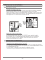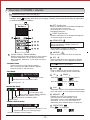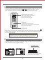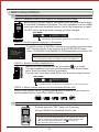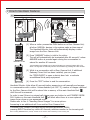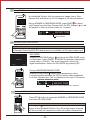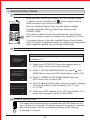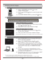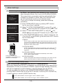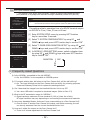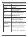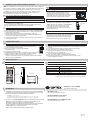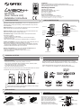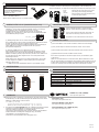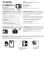
1
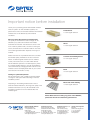
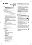
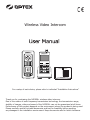
Wireless Video Intercom For a setup of each device, please refer to individual “Installation Instructions” Thank you for purchasing the iVISION+ wireless video intercom. Due to the nature of radio frequency transmission technology, the transmission range, stability of images, video and sound of the iVISION+ can not be guaranteed at all times. Performance of this product depends on the environment where the product is being used. Please carefully read all included documents and test for feasibility before applying any damages to the installation environment. Keep documents safe for future reference. iVISION+ User Manual INDEX 1. What you can do with iVISION+ 1-1. Basic features of iVISION+ 1-2. Expanding iVISION+ with additional units 2. Overview of iVISION+ devices 2-1. Handheld Monitor Unit (IVP-HU(G)) 2-2. Door Camera Unit (IVP-DU(G)) 2-3. Gateway Chime Unit (IVP-GU(G)) 3. Before Using iVISION+ 3-1. 3-2. 3-3. 3-4. 3-5. Getting ready with iVISION+ system How to ON/OFF the system Date and Time Setting Changing Volumes Changing Brightness on Handheld Monitor Unit 4. How to Use Basic Features 4-1. 4-2. 4-3. 4-4. Answering to a Door Camera Unit Using SNAP function to capture an image Operating OPEN DOOR function Ending ANSWER / BROWSING MODE (Returning to IDLE MODE) 5. Auto Recording Images 5-1. How “Auto Recording” works 5-2. Changing number of images to be captured in “Auto Recording” 5-3. Timings for capturing images 6. Handling Stored Images 6-1. Viewing Images 6-2. Deleting Stored Images 6-3. Viewing Images from Your PC 7. Other Settings 7-1. Talk Switching Mode Setting 7-2. Sensor Alert Enabling/Disabling Setting 7-3. Door Open Duration Setting 8. Frequently Asked Questions 9. Trouble Shooting -1- 1. What you can do with iVISION+ 1-1. Basic features of iVISION+ Knowing who is/was at your door iVISION+ is a wireless video intercom system with multi unit expansion capability. When someone comes to your door and presses the button on the Door Camera Unit (Max. 2 units), the Handheld Monitor Unit (Max. 4 units) rings a chime and displays a video image from the camera. The Handheld Monitor Unit will store still images even if no one is there to answer the call. Replace an old door bell with video If you already have a door bell with 10-24VAC/DC power supplied, enable Door Camera Unit for a browsing feature and actively view from a Handheld Monitor Unit anytime you like. Gateway Chime Unit adds a extra chime to let you know someone is at the door. 1-2. Expanding iVISION+ with additional units Operate third party equipments (e.g. Door lock) Connecting a third party equipment such as a door lock or a garage door activator to a relay output of Gateway Chime Unit (IVP-GU) can enable “OPEN DOOR” function on a Handheld Monitor Unit. Up to two units* of IVP-GU can be hosted in a iVISION+ system. * One IVP-GU can only be associated with one of two Door Camera Unit at all times. -2- 2. Overview of iVISION+ devices 2-1. Handheld Monitor Unit (IVP-HU(G)) Please make sure that all Handheld Monitor Units are on cradles and being charged. A battery mark appears while they are charging. Clearity of intercom sound may be dependent on radio transmission condition. LEFT function key Used for confirmation of a command that appears on the lower left of the screen. Press and hold for 3 sec to enter into SYSTEM SETUP menu. 20XX/XX/XX 11:59AM RIGHT function key Used for confirmation of a command that appears on the lower right of the screen. OPEN DOOR Enabled only when a third party electronic door lock is connected to iVISION+ system via OPTEX IVP-GU unit. Select DOOR1 or DOOR 2 to activate output relay on designated IVP-GU unit. ANSWER Press to answer a call from Door Camera Unit Monitor Screen / Status Indicator Monitor Screen shows video image from Door Camera Unit when PUSH button on the IVP-DU is pressed. Status Indicator appears for 10 sec when any button is pressed. OFF Press to terminate a talk. Lights when charging. Press and hold for 3 sec to ON/OFF the device. Unit 1 must remain “ON” for automatic recording function to be enabled. STANDBY MODE IVP-HU goes into a power saving condition after 10 seconds. No Status Indicator appears. Press any button to exit this mode. SNAP Press to capture an image while answering a call or when browsing a Door Camera Unit. IDLE MODE UP 20XX/XX/XX 11:59AM Current Date & Time Handheld Monitor Unit battery status DOWN IDLE MODE: Select a volume of a ring tone <> While Answer or Browse: Select a volume <> Device ID (from 1 - 4) BROWSING MODE PLAY 20XX/XX/XX 11:59AM Current Date & Time Door Camera Unit low battery indicator Door Camera Unit number (1 or 2) Handheld Monitor Unit battery status Signal status IMAGE VIEWING MODE IDLE MODE: Press to enter IMAGE VIEWING MODE Press and hold for 3 sec to delete all stored images. BROWSE Enabled only when Door Camera Unit is powered from an external power source. IDLE MODE: Press to enter BROWSING MODE Select Door 1 or Door 2 to view. Listen in or additionally press ANSWER button to speak out. BRIGHTNESS REC 1/500 20XX-XX-XX 11:59:59AM Door Camera Unit number (1 or 2) Captured Date & Time of viewing image Number / Number of stored images -3- Press to set brightness <> 2-2. Door Camera Unit (IVP-DU(G)) The Door Camera Unit is a device that makes a call to the Handheld Monitor Units (IVP-HU) when the push button is pressed by a visitor. Each iVISION+ system can carry up to 2 units of Door Camera Units and each is identified by or on Handheld Monitor Units. Camera Module with IR LEDs Auto Day and Night(IR) Vision enables color images in daytime and black & white images when dark. PUSH button The button glows with fluorescence after dark. If the unit powered by an external power, the button stays illuminated. MICROPHONE Please replace the batteries when Handheld Monitor Units show a low battery status indicator on upper middle of the screen. The sign indicates that Door Camera Unit has low power supply from current 3 AA batteries. Caution Do not mix an old and a new battery in this unit. Do not use Lithium batteries. Leakage or explosion can occur and may lead to severe damage and injuries. 2-3. Gateway Chime Unit (IVP-GU(G)) The Gateway Chime Unit is an extra chime and an open relay output device for the iVISION+. IVP-GU is required when expanding the iVISION+ system with another third party equipment such as a door lock and a garage door activator. Sound ON/OFF Switch This switch is for turning ON/OFF a speaker module. The Gateway Chime Unit always remain ON while power is being supplied. -4- 3. Before Using iVISION+ 3-1. Getting ready with iVISION+ system CHECK 1: Handheld Monitor Unit needs to be charged before usage Before using iVISION+ system, the system must be installed accordingly to individual Installation Instruction. Once the installation is done, please make sure that each Handheld Monitor Unit is fully charged on a cradle. The OFF button lights up while charging until fully charged. IDLE MODE 20XX/XX/XX 11:59AM This indicator shows battery status on the Handheld Monitor Unit. CHECK 2: Confirm devices registered in the system SYSTEM SETUP 1 2 3 4 DATE & TIME SYSTEM CONFIGURATION DEVICES IN NETWORK PC CONNECTION OK BACK To check number of iVISION+ devices in your system, press and hold LEFT function key for 3 sec to bring up a SYSTEM SETUP menu. Select “3 DEVICES IN NETWORK” by DOWN button and confirm OK. REFERENCE Installation Instruction of Handheld Monitor Unit [7-1 Confirming number of iVISION+ devices in a HOME ID] CHECK 3: Identify the Main Handheld Unit Identify the Main Handheld Unit by an indicator on a screen. The main handheld unit is the unit that captures and stores images while “Auto Recording Function”is activated. The main unit must stay turned ON for the “Auto Recording Function” IDLE MODE 20XX/XX/XX 11:59AM This indicator No. 1 is shown on the main unit. 2,3 & 4 are sub units. CHECK 4: Select a chime volume from the Handheld Monitor Unit While in IDLE MODE, Use UP and DOWN keys to select a chime volume for each Handheld Monitor Unit in the iVISION+ system. MUTE MAX < < < < 3-2. How to ON/OFF the system Pressing down the “OFF” button for 3 seconds, will turn ON/OFF the Handheld Monitor Unit. Caution At least one paired Handheld Monitor Unit needs to stay turned “ON” to respond to a call from the external Door Camera Unit. When the main Handheld Monitor Unit is turned off, Auto Recording feature does not work. -5- 3-3. Date and Time Setting Please enter SYSTEM SETUP menu by pressing down on LEFT function key for more than 3 seconds. (Changes in SETUP can only be made on HU1) SYSTEM SETUP 1 2 3 4 DATE & TIME SYSTEM CONFIGURATION DEVICES IN NETWORK PC CONNECTION OK BACK DATE & TIME SETUP Select “1 DATE & TIME” by using UP and DOWN and press LEFT function key to confirm “OK” Within a DATE & TIME SETUP MODE: Use UP and DOWN keys to increase / decrease a value Press PLAY to move to the next field. Complete the setup with OK. 20XX / XX / XX 11 : 59 AM OK BACK keys - While another HU is in ANSWER MODE, the Date & Time Setting will not be reflected on the unit. - When addtional IVP-HU are added in a system, please repeat process above to reflect the Date & Time Setting to new IVP-HU units. 3-4. Changing Volumes IDLE MODE Pressing Up and DOWN keys while on idle changes volume of the chime that ring out from the Handheld Monitor Units. ANSWERING/BROWSING MODE Pressing Up and DOWN keys while answering a call or browsing changes volume of the sound out from the Handheld Monitor Units. 3-5. Changing Brightness on Handheld Monitor Unit Dim Bright Click on Brightness to shift brightness of the screen. Brightness changes in 5 steps and repeats. -6- 4. How to Use Basic Features 4-1. Answering to a Door Camera Unit (1) When a visitor presses the PUSH button on a Door Camera Unit, all other iVISION+ devices in the system make a chime sound. The Handheld Monitor Units will automatically display a video image from the Door Camera Unit. (2) Press “ANSWER” button to talk to the visitor. The call will automatically be terminated after 60 seconds* unless ANSWER button is pressed again during the conversation to “ANSWER” to talk extend for another 60 seconds. *Conversations are limited to a 60 second duration to conserve battery life or for when it is forgotten to manually end the conversation by pressing the “OFF” button. (3) While in a conversation with a Door Camera Unit, if additional Gateway Chime Unit has been installed, you can press the “OPEN DOOR” to open a electric door lock or activate an additional third party equipment. “OFF” to end (4) Press the “OFF” button to end the conversation. Handheld Monitor Units allow 60 seconds before answering a call manually and engage in a conversation with a visitor. Unless disabled (ref: SEC. 5), number of images captured by the Door Camera Unit will be stored into a memory of the main Handheld Unit untill the call is answered. In order to see if there is a missed call please press any button to exit STANDBY MODE. PLAY button on the main Handheld Unit will blink when there is a new captured image from a time no one answered a call. Please refer to Sec. 6 “Handling Stored Images” for more options. Answering to an additional call from another Door Camera Unit If another Door Camera Unit calls during ANSWER/BROWSING MODE, pressing RIGHT function key within 60 seconds, switches monitor to the incoming call. Note: Pressing ANSWER button, instead, extends current session without switching to the incoming call. -7- 4-2. Using SNAP function to capture an image the Handheld Monitor Unit can capture an image from a Door Camera Unit and stores up to 500 images in an internal memory. During ANSWER or BROWSING MODE, press SNAP to record a still image from the Door Camera Unit. An REC Indicator in red will appear on the top of the screen for 1 second. 20XX/XX/XX 11:59AM REC Indicator 4-3. Operating OPEN DOOR function CAUTION OPEN DOOR function is only available if iVISION+ system is expanded with a Gateway Chime Unit(IVP-GU) and properly connected to a third party equipment. IDLE MODE OPEN DOOR DOOR1 DOOR2 Pressing OPEN DOOR button will bring an OPEN DOOR menu on the screen. Select DOOR1 or DOOR2 to activate a designated output relay on IVP-GU. Two short beeps will confirm the signal transmission. Return to IDLE MODE by pressing OFF. During ANSWER/BROWSING MODE Pressing OPEN DOOR button while answering a call or browsing directly activates the IVP-GU output relay designated to a Door Camera Unit. This is indicated on the top of the screen. ANSWER/BROWSING MODE 20XX/XX/XX 11:59AM Indicator for a Door Camera Unit in operation 4-4. Ending ANSWER / BROWSING MODE (Returning to IDLE MODE) Press OFF button to terminate ANSWER or BROWSING MODE and return to IDLE MODE. CAUTION Pressing OFF button for more than 3 seconds will turn off the power of the Handheld Monitor Unit. When the power is turned off the unit will not respond to a call from a Door Camera Unit. -8- 5. Auto Recording Images 5-1. How “Auto Recording” works Every time Door Camera Unit makes a call, untill ANSWER button is pressed, the main Handheld Unit capture images from the screen and stores into its internal memory. When the Handheld Monitor Unit has newly captured images from Auto Recording, PLAY button blinks when you exit STANDBY MODE. ! If you wish to disable the Auto Recording function, please follow step 5-2 for setting a number of images to be captured to “0” zero. The internal memory of the Main Handheld Monitor Unit can store up to 500 images. If additional images are captured and being stored, oldest images are deleted and overwritten automatically. 5-2. Changing number of images to be captured in “Auto Recording” NOTE SYSTEM SETUP 1 2 3 4 DATE & TIME SYSTEM CONFIGURATION DEVICES IN NETWORK PC CONNECTION OK BACK SYSTEM CONFIGURATION 1 NUMBER OF CAPTURING IMAGE 2 TALK SWITCHING SETUP 3 DOOR OPEN DURATION SETUP OK BACK PRESS UP OR DOWN KEY TO SET UP NUMBER OF CAPTURING IMAGE: 2 OK BACK By default, the number of images to be captured during Auto Recording is “2”. (1) Please enter SYSTEM SETUP menu by pressing down on LEFT function key for more than 3 seconds. and (2) Select “2 SYSTEM CONFIGURATION” by using UP DOWN keys and press LEFT function key to confirm “OK” (3) Select “1 NUMBER OF CAPTURING IMAGE” and press LEFT function key to confirm “OK” (4) Using UP and DOWN keys, select the number of images to be captured during “Auto Recording” from “0” zero to “10” ten. (5) Please press LEFT Function key to “OK” your selection. The screen will consequently return to IDLE MODE. 5-3. Timings for capturing images ! First image will be captured within a second after the PUSH button on the Door Camera Unit is pressed. The second image will be captured 4 seconds after the first image. The third and following images will be captured at intervals of 1 second. -9- 6. Handling Stored Images 6-1. Viewing Images (1) While in IDLE MODE, press PLAY IMAGE VIEWING MODE to enter (2) Use UP and DOWN keys to browse through stored images. (3) End IMAGE VIEWING MODE by pressing OFF button. 6-2. Deleting Stored Images CAUTION Please note that once images are deleted, they can not be restored. REC 1/500 20XX-XX-XX 11:59:59AM Deleting selected images in a memory (1) While in IMAGE VIEWING MODE, select image to delete by UP and DOWN keys. (2) Press RIGHT function key to delete the image. DELETE DELETE ALL IMAGES? OK BACK Deleting all images stored in a memory (1) While in IDLE MODE, press and hold PLAY button for more than 3 seconds. (2) If OK, press LEFT function key to delete all images. Recommended monthly deletion of all images to reduce a risk of memory failure. 6-3. Viewing Images from Your PC (1) Enter SYSTEM SETUP menu by pressing LEFT function key for more than 3 seconds. (2) Select “4 PC CONNECTION” by using UP and DOWN keys. Confirm “OK” by LEFT function key. CONNECT TO PC ? OK BACK (3) Make sure that the Handheld Monitor Unit is connected to a PC by micro-USB cable*1. and proceed with “OK” by pressing LEFT function key. PC CONNECTION MODE will start. (4) Your PC will recognize the Handheld Monitor Unit as an external storage device. Access the device to retrieve or manage stored image files*2. (5) Eject the storage device from the PC and confirm “BACK” by RIGHT function key to return to IDLE MODE. *1 micro-USB cable must be obtained separately from available electronics shops *2 PC may require addition procedures to recognize the device. Supports Windows 7 or later versions. ® - 10 - 7. Other Settings 7-1. Talk Switching Mode Setting By default, Talk Switching Setup between a Door Camera Unit and a Handheld Monitor Unit is set to AUTO(MIDDLE NOISE). This means that a conversation switches automatically from a listener to a speaker on either side of the intercom when an unit is picking up a voice or any relevant sound. If you wish to change the setting, please take following procedures. SYSTEM SETUP 1 2 3 4 DATE & TIME SYSTEM CONFIGURATION DEVICES IN NETWORK PC CONNECTION OK BACK SYSTEM CONFIGURATION 1 NUMBER OF CAPTURING IMAGE 2 TALK SWITCHING SETUP 3 DOOR OPEN DURATION SETUP OK BACK TALK SWITCHING SETUP PRESS UP OR DOWN KEY TO SET UP 1 MANUAL 2 AUTO(LOW NOISE) (1) Enter SYSTEM SETUP menu by pressing LEFT function key for more than 3 seconds. (2) Select “2 SYSTEM CONFIGURATION” by using UP and DOWN keys and press LEFT function key to confirm “OK” (3) Select “2 TALK SWITCHING SETUP” by using UP and DOWN keys and press LEFT function key to confirm “OK” (4) In TALK SWITCHING SETUP screen, select a mode from 1 to 4 by using UP and DOWN keys and press LEFT function key to confirm “OK”. 3 AUTO(MIDDLE NOISE) 4 AUTO(HIGH NOISE) OK BACK 1 MANUAL This is a “Push to talk” mode. Door Camera Unit only receives a voice or a sound from a Handheld Monitor Unit when LEFT function key is being pressed. Use this mode to avoid unwanted sound from the house to be heard from a Door Camera Unit. 2 AUTO(LOW NOISE) Listener and speaker side switches automatically in this mode. Use this in a very quiet and low noise environment to enhance conversational responses. 3 AUTO(MIDDLE NOISE) Press LEFT function key to speak to a Door Camera Unit (Effective in all settings) Listener and speaker side switches automatically in this mode. This is a factory default setting. 4 AUTO(HIGH NOISE) Listener and speaker side switches automatically in this mode. Use this with a noisy environment to enhance conversational responses. 7-2. Sensor Alert Enabling/Disabling Setting Note: This function is available only for U.S./Canada products. While Door Camera Unit(IVP-DU) is powered by an external power source and OPTEX Wireless2000 TD-20U is connected to iVISION+ system through Gateway Chime Unit, calls can be triggered by motion detectors, capturing images from the IVP-DU. In order to change this setting, enter ENABLE/DISABLE SENSOR ALERT menu by pressing RIGHT function key for more than 3 seconds. Confirm by LEFT fucntion key to switch setting or cancel by RIGHT function key. Sensor Alert Enabled: TD-20U triggers a call to iVISION+ system. Sensor Alert Disabled: TD-20U does not trigger a call to iVISION+ system. - 11 - 7-3. Door Open Duration Setting* * This setting is only active while iVISION+ system is properly connected to a third party doorlock or a garage door activator through a Gateway Chime Unit (IVP-GU). SYSTEM SETUP NOTE 1 2 3 4 DATE & TIME SYSTEM CONFIGURATION DEVICES IN NETWORK PC CONNECTION OK BACK SYSTEM CONFIGURATION 1 NUMBER OF CAPTURING IMAGE 2 TALK SWITCHING SETUP 3 DOOR OPEN DURATION SETUP OK BACK DOOR OPEN DURATION SETUP 1 DOOR1 OPEN DURATION 2 DOOR2 OPEN DURATION OK BACK DOOR1 OPEN SETTING DURATION: 1 SEC OK BACK By default, DOOR OPEN DURATION Setting is 1 second*. * The actual duration that the third equipment operate may differ from this setting. This setting adjust a operation time of a NO/NC terminal output on IVP-GU to 1 sec, 5 sec, 30 sec or 60 sec. (1) Enter SYSTEM SETUP menu by pressing LEFT function key for more than 3 seconds. (2) Select “2 SYSTEM CONFIGURATION” by using UP and DOWN keys and press LEFT function key to confirm “OK” (3) Select “3 DOOR OPEN DURATION SETUP” by using UP and DOWN keys and press LEFT function key to confirm “OK” (4) In DOOR1(2) OPEN SETTING screen, select a duration time by using UP and DOWN keys and press LEFT function key to confirm “OK”. DURATION: 1 SEC 5 30 60 8. Frequently Asked Questions Q: Is the iVISION+ compatible to the old iVISION? A: No, the iVISION+ is not compatible to iVISION system. Q: If I connect existing door bell wires to the Door Camera Unit, will the bell still ring? A: No. The input terminals on the Door Camera Unit are strictly for powering purposes. Please use Gateway Chime Unit to replace the existing doorbell. Q: Can I download the images from the Handheld Monitor Unit to my PC? A: Yes. micro-USB cable is required to download images. (Refer to Sec. 6-3) Q. What is the RF transmission range for iVISION+? A: Signal reaches a maximum of three hundred ft (100 m) (clear line of site). RF signal condition may vary depending on surrounding environment and materials. Q: How many Handheld Monitor Units can I have communicating to a Door Camera Unit? A: One at a time. If another Door Camera Unit makes a call while answering, the call can be only answered from the current Handheld Monitor Unit. Q: How can I adjust the volume on the Door Camera Unit? A: There is no volume adjustment for the Door Camera Unit. - 12 - 9. Trouble Shooting Symptoms Probable causes & solutions The video image is distorted. The voice is cut off while answering/browsing a Door Camera Unit. Is a microwave oven or a wireless LAN device in operation near the Handheld Monitor Unit? 5HORFDWHWKH+DQGKHOG0RQLWRU8QLWDZD\IURP such equipment. A howling noise distorts the sound. If the Handheld Monitor Unit is too close to the Door Camera Unit, a howling sound can occur. 3OHDVHPRYHWKH,93+8DZD\IURP,93'8XQWLOO the howling sound disappears. The ring tone cannot be heard. &KHFNEDWWHU\VWDWXVRQ+DQGKHOG0RQLWRU8QLWDQG charge if necessary. Change volume setting on the Handheld Monitor Unit. (Refer to Sec. 3-1 “Check 4”) The charging does not start when the Handheld Monitor Unit is placed in the charging cradle. Is the AC adaptor disconnected from the socket or the charging cradle? 3OHDVHFKHFNDOOSRZHUFRQQHFWLRQV &OHDQWKHFKDUJLQJWHUPLQDOVZLWKDGU\FORWK The display on a Handheld Monitor Unit is black and does not respond to any key. Is the unit in standby? 3UHVVDQ\EXWWRQWRHQHUJL]HWKHGLVSOD\ 0DNHVXUHWKHXQLWLVSRZHUHGRQ5HIHUWR6HF ,IWKHEDWWHU\KDVUDQRXWFKDUJHWKH+DQGKHOG Monitor Unit. The video image flickers. Fluorescent lights nearby to the Camera Door Unit may cause the image to flicker. The video image appears blurred by lights. It may be difficult to see the image if the camera lens receives strong light such as sunlight. $YRLGGLUHFWVXQOLJKWE\UHSRVLWLRQLQJRUSODFLQJDVKDGH $GMXVWWKHEULJKWQHVVVHWWLQJ5HIHUWR6HF During PLAY function, viewing stored images is slow. Please clear out all stored images by refering to Sec. 6-2 “Deleting all images stored in a memory”. This will format a memory and improve a viewing speed. Do not forget to make a PC backup of images if necessary. The Handheld Monitor Unit has a very short battery life. If the units had not been powered for a long time, it may require to repeat charge-discharge process for several times to rejuvenate a battery life. If the battery life does not improve, please contact our technical assistance. - 13 - MEMO - 14 - OPTEX CO., LTD. (JAPAN) URL: http://www.optex.net/ OPTEX INC. (U.S.) URL: http://www.optexamerica.com/ OPTEX TECHNOLOGIES B.V. (The Netherlands) OPTEX PINNACLE INDIA, PVT., LTD. (India) URL: http://www.optex.net/in/en/sec/ URL: http://www.optex.nl/ OPTEX DO BRASIL LTDA. (Brazil) URL: http://www.optex.net/br/es/sec/ OPTEX KOREA CO.,LTD. (Korea) OPTEX SECURITY SAS (France) URL: http://www.optexkorea.com/ URL: http://www.optex-security.com/ OPTEX (EUROPE) LTD. / EMEA HQ (U.K.) URL: http://www.optexeurope.com/ OPTEX SECURITY Sp.z o.o. (Poland) OPTEX (DONGGUAN) CO.,LTD. SHANGHAI OFFICE (China) URL: http://www.optex.com.pl/ URL: http://www.optexchina.com/ 5923320 REV 1.01 Important notice before installation Thank you for purchasing the OPTEX iVISION+ wireless intercom system. As with all wireless systems, the performance of the communication between the individual wireless units can be affected by environmental conditions. Plasterboard 10-30% signal reduction What can affect the wireless communication? The quality of the iVISION+’s radio coverage can be affected by any obstruction between the wireless transmitter and receiver. The obstruction can be in the form of solid or partition walls, concrete or other types of floor, armoured doors or elevator shaft etc. The level of the radio signal attenuation depends on the type of material. Wood 10-30% signal reduction Please note that not only visible obstructions can affect the wireless quality; interference can also come from electric or electromagnetic devices such as wireless routers, microwave ovens, TV’s and similar devices. OPTEX iVISION+ operates on 2.4GHz frequency which is a popular wireless frequency. The risk of interference can be minimised by changing the WIFI channel on the wireless router for example (please refer to your router’s user manual for information on this). Concrete and building blocks 50-70% signal reduction Brick 30-50% signal reduction Testing for optimised operation We recommend any user / installer to test the wireless coverage on site system before deciding on the final installation position. Metal and metal cladding 70-90% signal reduction Depending on the building material used on site or external wireless interference, the range and quality of the wireless transmission can vary. We have listed some examples to explain how some materials affect the wireless signal. Please Note: before mounting any piece of the iVISION+, please test the unit for satisfactory performance. OPTEX (EUROPE) LIMITED EMEA Headquarters T: +44 (0)1628 631 000 Dubai branch T: +971 (0)4 501 53 94 E: [email protected] www.optex-europe.com OPTEX Security SAS (France, Germany, Austria, Switzerland and North Africa) OPTEX Security SAS T: +33 (0)4 37 55 50 50 E: [email protected] www.optex-security.com OPTEX Security Sp. z o.o. (Eastern Europe, CIS countries, Turkey) Optex Security Sp. z o.o. T: +48 (22) 598 06 60 E: [email protected] www.optex.com.pl OPTEX Technologies BV (Benelux) OPTEX Technologies B.V. T: +31 70 4194100 E: [email protected] www.optex.eu ATTENTION: Thank you for purchasing the iVISION+ wireless video intercom. Before installation and usage, please read this instruction manual thoroughly and keep this safe for future reference. Wireless Video Intercom IVP-HU(G) features IVP-HU(G) (Handheld Monitor Unit) Installation Instructions 1. 2.4 inch TFT LCD Monitor Wall-mountable Cradle Max 4 Units in a System micro-USB port to PC connection Manual/Auto Talk Switching IMPORTANT NOTICE Operations under harsh environments such as out of warranted temperature, rapid temperature change, high humidity, constant moisturization may cause the unit to malfunction. Avoid using the Handheld Monitor Unit in the following areas - Close to a fire, thermal appliance or other source of extreme heat/cold. - Within 10ft (3m) of a television, microwave oven, personal computer, wireless LAN equipment, wireless audio/visual equipment - the radio frequency waves emitted by these devices can affect operation. - In direct sunlight. - Where extreme fluctuations in temperature can occur - if moving the unit from a warm to cold environment, or vice versa, please allow 30 minutes before use. Electronic device such as TVs, Radios, PCs, Microwave ovens or any other device with an electric motor may cause the unit to malfunction. Impact or shocks can cause severe damage to the unit. Please handle the unit with care and operate without exerting strong forces. Transmission range of communication between units may decrease under the following conditions. - Any unit is installed on a metal surface. - Presence of reinforced concrete, steel doors or other metal construction materials between units. - Places near strong radio sources such as broadcast stations or substations. 2. Privacy & portrait/image rights - Please respect the privacy and image rights of others when using this equipment. By using this equipment the user assumes total responsibility in upholding these rights. - Images stored must not be used for any purpose other than that for which the equipment is designed. - Images should be deleted once no longer required. PARTS IDENTIFICATION LCD display Speaker LEFT function key RIGHT function key “ANSWER” “OPEN DOOR” “OFF” “SNAP” “PLAY” “BROWSE” “BRIGHTNESS” Charging Cradle AC Adaptor Battery Cover Scroll buttons ( UP/ DOWN) Microphone Handheld Monitor Unit 3. Pairing button USB connection port Battery Pack Battery Pack Compartment 4. CHOOSING LOCATION The performance of the iVISION+ system is dependent on the radio frequency environment and distances between devices. Following materials may decrease the maximum transmission distance and may cause the Handheld Monitor Unit inability to respond to incoming signals. Mounting Screw INSTALLATION Handheld Monitor Unit must be set on Charging Cradle to retain its power while iVISION+ system is not in operation. The Charging Cradle can either be free-standing on a horizontal surface or be mounted on a wall as described below. • Metal barricades such as ,metal doors and shutters. • Walls with aluminium foil insulation. • Concrete or galvanized metal walls. The effective communication range is around 300ft (100m) in an open air condition (line of sight). This range will be significantly reduced by the number and thickness of walls through which the signal is required to pass. Please keep to a minimum number of walls wherever possible. Handheld Monitor Units use 2.4GHz radio frequency. Any electrical appliance may become a potential cause for malfunction. Please avoid using the Handheld Monitor Unit near microwave oven or any electrical devices with similar radio frequency. 5. POWERING THE UNIT CAUTION 1. Connect Battery pack to the main unit. 2. Connect AC adapter to Charging Cradle Please use the included battery pack and a power adaptor only. Do not disassemble or attempt to use alternative battery packs. Remove and keep the battery seperately if the device is not used for more than a month. It may require several charge-discharge process before a battery regains its full capacity after a long storage period. 3. Press and hold “OFF” button to power on. Set the unit onto the cradle for charging. 6. PAIRING WITH OTHER iVISION+ DEVICES NOTE: One Handheld Monitor Unit (IVP-HU) must be configured to have a HOME ID*1 prior to paring up with other iVISION+ devices. Handheld Monitor Unit bundled with Door Camera Unit already has a HOME ID set up and paired up to each other. *1 HOME ID is an unique network identification protocol for iVISION+ system. One Handheld Monitor Unit can issue the HOME ID and all other devices on the same system must be assigned the same HOME ID. 6-1 How to create HOME ID by a Handheld Monitor Unit (1) Press “OFF” and then press pairing button in the back of the unit once. The IVP-HU will be in a pairing mode. (2) Press the pairing button again and hold until the unit makes a beep sound. (3) Press “Left function key” on the front to confirm “CREATE.” How to enroll other iVISION+ devices to the Handheld Monitor Unit (1) Press pairing button in the back of IVP-HU. The unit will be in “PAIRING MODE”. (2) Proceed to “SCAN” by pressing “Left function key”. IVP-HU starts scanning for other devices for 60 seconds. (3) Prepare other iVISION+ device into their pairing mode. (REF: 6-3) When the device is ready, the new unit will be enrolled to the HOME ID and IVP-HU shows which device was connected. (4) If another device needs to be enrolled, re-enter “SCAN” by “Left Function key” and repeat the process. 7-1 IVP-DU: Door Camera Unit Pairing Button IVP-HU: Handheld Monitor Unit Any pre-existing HOME ID set up will be cleared out with this procedure. 7. REFERENCE: How to enter “pairing mode” in iVISION+ devices If not purchased in a bundle package, IVP-DU is in the pairing mode when powered up. IVP-DU beeps continuously when PUSH button is pressed. To purposely enter into a paring mode, press PUSH button once and hold a pairing button in a back. WARNING 6-2 6-3 If not purchased in a bundle package, IVP-HU is in the pairing mode when powered up. Choose “JOIN” by “Right function key” to enroll into an existing HOME ID. If otherwise, follow the instruction 6-1 to create a new HOME ID. After an enrollment of new HU, reset a Time & Date on HU1 to reflect the setting onto the added HU unit. Pairing button IVP-GU: Gateway Chime Unit If not purchased in a bundle package, by the factory default, IVP-GU is in the pairing mode when powered up. IVP-GU beeps continuously and green/red LED blinks. Press down both A and B buttons while powering up the Gateway Chime Unit to enter the pairing mode. Sound ON/OFF Switch Pairing button A & B OPERATION CHECK 7-2 Confirming number of iVISION+ devices in a HOME ID (1) In a normal operation mode, press and hold the left function key for two seconds to enter menu mode. (2) Select menu number 3 # DEVICES IN NETWORK by up and down key. (3) Press LEFT function key to “OK” (4) The display will show the number of iVISION+ devices in the network. Confirm number of iVISION+ devices registered with the HOME ID. (5) Maximum numbers of devices in an iVISION+ system are; 2 IVP-DU, 2 IVP-GU and 4 IVP-HU. Go over pairing procedure unless optimal numbers of devices are displayed. SYSTEM SETUP 1 DATE & TIME 2 SYSTEM CONFIGURATION 3 DEVICES IN NETWORK 4 PC CONNECTION OK 8. SPECIFICATION 8-1 Dimensions BACK 8-2 Specification Table MODEL NAME: OPTEX iVISION+ (IVP-HU) Handheld Monitor Unit 30mm / 1.18” 60mm / 2.36” Checking operations on Handheld Monitor Unit (1) Make sure IVP-HU has been charged and there is a green indication on the top of display. (2) To confirm RF reception, bring IVP-HU and IVP-DU in a line of sight. (3) Press “Push button” on a paired Door Camera Unit. All paired IVP-HUs display an image from the IVP-DU. (4) Press “Answer” on any of the IVP-HU. Voice from IVP-HU will be heard from the IVP-DU. (5) Press “OFF” on the IVP-HU to terminate the communication. (6) Move IVP-HU (and IVP-DU) to a desired location and repeat (3) to (5) to confirm reception of signals. 80mm / 3.15” 145mm / 5.71” Operating Temperature 0 to 40 degC (32 to 104 degF) Operating Humidity < 90% RH (no condensation) Dust/Water Protection N/A (Indoor Use Only) Radiowave Frequency 2.4 GHz Power Power Adaptor 5.5V DC Use designated battery, IVP-BAT, for IVP-HU. Please contact your regional technical support for procurement information. 71mm / 2.8” 9. OPTEX CO., LTD. (JAPAN) WARRANTY 1. This product is under a warranty for a normal usage for 18 months from the date of manufacturing. The date of manufacturing can be identified from a LOT number indicated on a label placed in battery compartment of IVP-HU. LOT: YYWWZ (e.g. LOT 1350Z) YY indicates last two digits of the year manufactured (e.g. 13 = Year 2013) WW indicates Xth week of the year manufactured (e.g. 50 = 50th week) 2. The warranty may not be applicable when any of following circumstances is found. - Mechanical or electrical modification is made to the product and the good’s appearance indicates an alterations or a significant damage. - The product is already been diagnosed by someone other than the manufacturer. - Product malfunction is resulting from an improper usage, an accident, natural disaster or any environmental event. - Please call our technical assistance before arranging a return. URL: http://www.optex.net/ OPTEX INC. (U.S.) URL: http://www.optexamerica.com/ OPTEX DO BRASIL LTDA. (Brazil) URL: http://www.optex.net/br/es/sec/ OPTEX (EUROPE) LTD. / EMEA HQ (U.K.) URL: http://www.optexeurope.com/ 5923200 REV 1.02 ATTENTION: Thank you for purchasing the iVISION+ wireless video intercom. Before installation and usage, please read this instruction manual thoroughly and keep this safe for future reference. IVP-DU(G) features Adjustable Camera Angle Battery Operation Capability (for 1 year*1) Auto Day(Color) / Night(IR) Vision Max 2 Units in a System Fluorescent Push Button AC/DC (10~24V) Adaptable Splash Proof for Rain and Outdoor Condition*2 Wireless Video Intercom IVP-DU(G) (Door Camera Unit) Installation Instructions 1. *1 calculation based on operations for 10sec times 3 activations per a day *2 IPX4 Operating Temparature -20 to 50 degC (-4 F to 122 degF) 2. IMPORTANT NOTICE Operations under harsh environments such as out of warranted temperature, rapid temperature change, high humidity, constant moisturization may cause the unit to malfunction. PARTS IDENTIFICATION Camera Angle Adjustment Lever Camera Lens Electronic device such as TVs, Radios, PCs, Microwave ovens or any other device with an electric motor may cause the unit to malfunction. Battery Compartment Impact or shocks can cause severe damage to the unit. Please handle the unit with care and operate without exerting strong forces. Push Button Transmission range of communication between units may decrease under the following conditions. - Any unit is installed on a metal surface. - Presence of reinforced concrete, steel doors or other metal construction materials between units. - Places near strong radio sources such as broadcast stations or substations. Door Camera Unit (Front) 3-1 Places to Avoid Door Camera Unit (Back) Cable Hole Knock Out Old and new batteries may not be mixed. Do not use lithium batteries for IVP-DU. Leakage or possible explosion can occur. - When Door Camera Unit Low Battery Indicator blinks on HU1, please replace batteries. CHOOSING LOCATION 10 24 Fixing Screw Speaker Location of Installation is critical to optimize image quality captured by the unit. Images will be impaired if the ambient backlight is very strong. Please study the installation environment according to this installation instruction. - The video image is displayed in color during daytime or in well-lit area, but it is displayed in black and white at night or in a dark area. 3. External Power Input Pairing Button Microphone Battery Cover 3-2 The performance of the system may be affected when mounting the unit in the following environments. - Places that are constantly experiencing vibrations or shocks. - Near a source of hydrosulfuric fumes, phosphorus fumes, ammonia, sulphur, carbon dust and any acidic or noxious materials. - An enclosed space that may cause sounds to echo - Where rain or water may directly hit the unit. Wall Mounting Base Screws & Anchors Position and Field of View IVP-DU (Door Camera Unit) should be mounted at a position where visitors or potential trespassers can be captured in the camera’s field of view. In a typical setting, IVP-DU is positioned at height between 3.6 -5 feet (1-1.5m) off the ground. Camera Angle Adjustment Lever can shift the camera’s field of view max +/- 15 degrees to any combination of vertical and horizontal directions. Please also note that the video image may be seriously impaired where the camera faces directly into the sun, and also in the following situations. view downwards Location where the background is primarily occupied by the sky, such as in the upper floor of an apartment building. Location which has an adjacent white wall that will directly reflect sunlight. Location that receives direct bright sunlight. 4. INSTALLATION 4-1 Unit Preparation 4-2 Open a screw cover and loosen the screw. Pull out the screw for a quarter of an inch (6mm). Insert a driver into a small cavity on a rim to pop up the main unit. Fixing the Base Fix the mounting base on the wall at the height and location selected. Remove the main unit from the mounting base Lift the main unit from the mounting base. NOTE: When using an external power source, make a knockout hole on the Mounting Base before fixing to a wall. Place the Mounting Base on a horizontal surface front side down. Point a driver in the center of the knock out and apply gentle impacts to break a hole through. Mounting Screws Knock Out Holes drilled in wall Wall Mounting Base 4-3 Powering the Unit The Camera Door Unit may also be powered from an external power source. If available, connect the unit directly to the existing AC/DC 10-24V doorbell power supply or, alternatively, an AC/DC 10-24V third party’s external power pack may be used. CAUTION Old and new batteries may not be mixed. Do not use lithium batteries for IVP-DU. Leakage or possible explosion can occur. Power input terminal Pass the bell wire or the wire from a power pack through the mounting plate before fixing the plate to the wall. Connect the wire to the Power input terminal. Insert 3 x AA alkaline batteries. Please ensure to match the correct +/- polarity as shown. WARNING External power must not be used with batteries. 5. PAIRING WITH IVP-HU (Handheld Monitor Unit) 6. MOUNTING THE UNIT NOTE: One Handheld Monitor Unit (IVP-HU) must be configured to have a HOME ID*1 prior to paring up with other iVISION+ devices. For setting up a new HOME ID, refer to the Installation Instruction of IVP-HU. A Handheld Monitor Unit bundled with Door Camera Unit already has a HOME ID set up and paired up to each other. Proceed to OPERATION CHECK unless additional pairing is required. (1) Fix a Wall Mounting Base to a desired location using four screws and anchors included in a package. (2) On to the secured mounting base, hook upper rim of the main unit and then, press in the entire unit. (3) Tighten a screw at the bottom to secure the unit. Pairing Button (1) Enabling Paring Mode of a Door Camera Unit (IVP-DU) Press a PUSH button on the front then push pairing button located at the bottom of battery compartment until the unit makes a beeping sound. The Door Camera Unit will clear its HOME ID assignment and starts looking for a New HOME ID. 5 short beeps will repeat until the unit is paired or power/batteries displacement. (2) Assigning a HOME ID to a Door Camera Unit (IVP-DU) When a Handheld Monitor Unit in a paring mode, choose “SCAN” by pressing Left Function Key. Door Camera Unit will automatically be assigned to a new HOME ID and beeping will stop. Repeat the same procedure for an addition unit. The first paired IVP-DU will be assigned as DU1. The second paired IVP-DU will be assigned as DU2. NOTE: While the Door Camera Unit is in a factory default setting, the unit has not been assigned to a HOME ID*1. When powering the unit, 5 short beeps indicates its paring mode. *1 HOME ID is an unique identification number for your iVISION+ system. 8. SPECIFICATION 8-1 Dimensions 7. OPERATION CHECK (1) Press “Push Button” on the IVP-DU and observe IVP-HU with a visual image. (2) Carry IVP-HU away from the IVP-DU and Press “Answer” on the IVP-HU. (3) Have another person speak to the IVP-DU and listen to the sound on IVP-HU. (4) Speak back from the IVP-HU and listen from the IVP-DU. If the IVP-DU is powered from the external power source, the Push Button glows on the IVP-DU. NOTE: Due to characteristics of 2.4 GHz radio waves, different locations in a home may vary the performance of transmissions and receptions. Adjust positions of IVP-HU to places where performance is desirable. If a distance between IVP-DU and IVP-HU is close, two units may cause an howling effect when communication is in place. 8-2 Specification Table MODEL NAME: OPTEX iVISION+ (IVP-DU) Door Camera Unit 70mm / 2.76” 40mm / 1.57” 162mm / 6.38” 40mm / 1.57” 120mm / 4.72” Operating Temperature - 20 to 50 degC (-4 to 120 degF) Operating Humidity < 90% RH (no condensation) Dust/Water Protection IPX4 Splash Proof (Water Drain Structure) Radiowave Frequency 2.4 GHz Camera/Lighting Unit Color vision / IR lighting LED Power Battery (3 AA Alkaline) or AC/DC 10-24V 3W (max) Battery Life Expectancy 12 month * * Based on 3 activations (approx. 10sec each) per day 9. OPTEX CO., LTD. (JAPAN) WARRANTY 1. This product is under a warranty for a normal usage for 18 months from the date of manufacturing. The date of manufacturing can be identified from a LOT number indicated on a label placed in a back of IVP-DU. LOT: YYWWZ (e.g. LOT 1350Z) YY indicates last two digits of the year manufactured (e.g. 13 = Year 2013) WW indicates Xth week of the year manufactured (e.g. 50 = 50th week) 2. The warranty may not be applicable when any of following circumstances is found. - Mechanical or electrical modification is made to the product and the good’s appearance indicates an alterations or a significant damage. - The product is already been diagnosed by someone other than the manufacturer. - Product malfunction is resulting from an improper usage, an accident, natural disaster or any environmental event. - Please call our technical assistance before arranging a return. URL: http://www.optex.net/ OPTEX INC. (U.S.) URL: http://www.optexamerica.com/ OPTEX DO BRASIL LTDA. (Brazil) URL: http://www.optex.net/br/es/sec/ OPTEX (EUROPE) LTD. / EMEA HQ (U.K.) URL: http://www.optexeurope.com/ 5923140 REV 1.02 ATTENTION: Thank you for purchasing the iVISION+ wireless video intercom. Before installation and usage, please read this instruction manual thoroughly and keep this safe for future reference. IVP-GU(G) features Wireless Video Intercom “OPEN DOOR” Relay Output Function AC/DC (10~24V) Adaptable Chime On-Off Mode IVP-GU(G) (Gateway Chime Unit) Installation Instructions 1. * Relay Output function must meet other requirements dependent on the third party equipment. OPTEX will not be held responsible for any damage or injuries caused due to using this function. 2. IMPORTANT NOTICE Operations under harsh environments such as out of warranted temperature, rapid temperature change, high humidity, constant moisturization may cause the unit to malfunction. Electronic device such as TVs, Radios, PCs, Microwave ovens or any other device with an electric motor may cause the unit to malfunction. Impact or shocks can cause severe damage to the unit. Please handle the unit with care and operate without exerting strong forces. Transmission range of communication between units may decrease under the following conditions. - Any unit is installed on a metal surface. - Presence of reinforced concrete, steel doors or other metal construction materials between units. - Places near strong radio sources such as broadcast stations or substations. While installing/using a Gateway Chime Unit - Do not install/use in damp, steamy or dusty environments. - Do not hold the Gateway Chime Unit to your ear - your hearing could be damaged. - Do not install in an unstable location or where subject to strong vibration. 3. Pairing button A& B LED Indicator If there is a pre-existing door bell inside the house, a Gateway Chime Unit (IVP-GU) may be capable of adapting the pre-existing power wires (AC/DC 10-24V 3 Wmax). IVP-GU should be located in a place where the unit has a clear signal reception and transmission availability. The performance of a IVP-GU is dependent on the transmission environment of radio signals from locations of connecting units. A communication range will be significantly reduced by more number and thickness of walls which the signal is required to pass. For iVISION+ system, maximum communication range is around 300ft (100m) in an open air environment. Following materials may decrease the maximum communication range and may potentially cause loss of transmission signals. • Metal barricades such as metal doors and shutters. • Walls with aluminium foil insulation. • Concrete or galvanized metal walls. Gateway Chime Unit uses 2.4GHz radio frequency for iVISION+ system. 4. PARTS IDENTIFICATION Chime ON/OFF switch Mounting Screw Relay output Mounting Plate Speaker Power input CHOOSING LOCATION POWERING THE UNIT The Gateway Chime Unit needs to be powered from an AC/DC 10-24V 3W(max) power source. An open ended third party power adapter may be available from local electronics stores. Power input has no polarity. Please make sure to tighten terminal screws to avoid loose ends. If applicable, configure all pairing setup and carry out feasibility study before mounting on a wall. Fixing Screw Gateway Chime Unit (Back) Gateway Chime Unit (Front) 5. INSTALLATION One iVISION+ system can host up to 2 units of Gateway Chime Unit (IVP-GU). If “OPEN DOOR” Relay Output function is used, please carefully choose a location for each of IVP-GU to secure a physical access to the IVP-GU. For the optimal radio performance, mount IVP-GUs high on a wall and in an open area avoiding a metal surface and surrounding. 21mm / 0.83 Mounting Screw to Relay output (optional) to Power input Mounting Plate to a third party equipment N.C. N.O. Relay output to a power source Power input AC/DC 10-24V (1) Fix a Mounting Plate on a feasible location Slide on COM (2) Run a power cable to the location and connect to the Power input. If applicable, also run a relay connection from the Relay output to the third party equipment. Tighten a screw (3) Slide the IVP-GU onto the Mounting Plate and tighten the Fixing Screw at the bottom. 6. PAIRING WITH OTHER iVISION+ DEVICES One iVISION+ system can host up to 2 units of Gateway Chime Unit (IVP-GU). Sound ON/OFF Switch NOTE: One Handheld Monitor Unit (IVP-HU) must be configured to have a HOME ID*1 prior to paring up with other iVISION+ devices. For setting up a new HOME ID, please refer to the Installation Instructions of IVP-HU. A Handheld Monitor Unit bundled with Door Camera Unit (IVP-DU) already has a HOME ID set up and paired up to each other. This switch is for turning ON/OFF a speaker. Pairing button A & B While the IVP-GU is in a factory default setting, the unit has not been assigned to a HOME ID. When powering the unit, green and red LED will flash with beep sound to indicate its paring mode. Please proceed to (2). (... continues onto the other side) The Gateway Chime Unit operates regardless of the switch setting while power is being supplied. *1 HOME ID is an unique identification number for your iVISION+ system. (1) Entering Pairing mode of a Gateway Chime Unit (IVP-GU). An IVP-GU is already set in a “Pairing mode” at the factory default setting. To change IVP-GU into the “Pairing mode”, press down both A and B buttons and hold until LED will brink in green and red. Pairing button (2) Prepare Handheld Monitor Unit (IVP-HU) for assigning a HOME ID for IVP-GU. Press “Paring Button” on the back of an IVP-HU and choose “SCAN” by clicking “left function key” on the IVP-HU. The IVP-HU starts scanning for a new device. (3) Confirming IVP-GU with a HOME ID. When IVP-GU is assigned a new HOME ID, beeping stops and LED stops flashing to indicate the normal operation mode. 7. Handheld Monitor Unit (IVP-HU) ADDITIONAL SETTING To change a chime volume of IVP-GU – Press button A to acknowledge current chime volume level. Press A button again to change volume level to the next. The volume changes within 4 levels and the lowest volume will follow the loudest. Leave the setting at the desirable volume level. To completely turn off the chime, set Sound ON/OFF Switch to OFF. 8. SPECIFICATION 8-1 Dimensions 8-2 Specification Table MODEL NAME: OPTEX iVISION+ (IVP-GU) Gateway Chime Unit 80mm / 3.15” 110mm / 4.33” 9. Operating Temperature 0 to 40 degC (32 to 104 degF) Operating Humidity Dust/Water Protection < 90% RH (no condensation) Radiowave Frequency Power 2.4 GHz and 418MHz AC/DC 10-24V 3W(max) Relay Output 1C 50VAC/24VDC 1A max N/A (Indoor Use Only) 30.3mm / 1.2” OPTEX CO., LTD. (JAPAN) WARRANTY 1. This product is under a warranty for a normal usage for 18 months from the date of manufacturing. The date of manufacturing can be identified from a LOT number indicated on a label placed in a back of IVP-GU. LOT: YYWWZ (e.g. LOT 1350Z) YY indicates last two digits of the year manufactured (e.g. “13” = Year 2013) WW indicates Xth week of the year manufactured (e.g. “50” = 50th week) 2. The warranty may not be applicable when any of following circumstances is found. - Mechanical or electrical modification is made to the product and the good’s appearance indicates an alterations or a significant damage. - The product is already been diagnosed by someone other than the manufacturer. - Product malfunction is resulting from an improper usage, an accident, natural disaster or any environmental event. - Please call our technical assistance before arranging a return. URL: http://www.optex.net/ OPTEX INC. (U.S.) URL: http://www.optexamerica.com/ OPTEX DO BRASIL LTDA. (Brazil) URL: http://www.optex.net/br/es/sec/ OPTEX (EUROPE) LTD. / EMEA HQ (U.K.) URL: http://www.optexeurope.com/ 5923260 REV 1.00