1
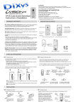
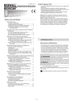
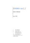
Wireless Video Intercom
For a setup of each device, please refer to individual “Installation Instructions”
Thank you for purchasing the iVISION+ wireless video intercom.
Due to the nature of radio frequency transmission technology, the transmission range,
stability of images, video and sound of the iVISION+ can not be guaranteed at all times.
Performance of this product depends on the environment where the product is being used.
Please carefully read all included documents and test for feasibility before applying
any damages to the installation environment. Keep documents safe for future reference.
iVISION+ User Manual
INDEX
1. What you can do with iVISION+
1-1. Basic features of iVISION+
1-2. Expanding iVISION+ with additional units
2. Overview of iVISION+ devices
2-1. Handheld Monitor Unit (IVP-HU)
2-2. Door Camera Unit (IVP-DU)
2-3. Gateway Chime Unit (IVP-GU)
3. Before Using iVISION+
3-1.
3-2.
3-3.
3-4.
3-5.
Getting ready with iVISION+ system
How to ON/OFF the system
Date and Time Setting
Changing Volumes
Changing Brightness on Handheld Monitor Unit
4. How to Use Basic Features
4-1.
4-2.
4-3.
4-4.
Answering to a Door Camera Unit
Using SNAP function to capture an image
Operating OPEN DOOR function
Ending ANSWER / BROWSING MODE (Returning to IDLE MODE)
5. Auto Recording Images
5-1. How “Auto Recording” works
5-2. Changing number of images to be captured in “Auto Recording”
5-3. Timings for capturing images
6. Handling Stored Images
6-1. Viewing Images
6-2. Deleting Stored Images
6-3. Viewing Images from Your PC
7. Other Settings
7-1. Talk Switching Mode Setting
7-2. Sensor Alert Enabling/Disabling Setting
7-3. Door Open Duration Setting
8. Frequently Asked Questions
9. Trouble Shooting
-1-
1. What you can do with iVISION+
1-1. Basic features of iVISION+
Knowing who is/was at your door
iVISION+ is a wireless video intercom system with multi unit expansion capability.
When someone comes to your door and presses the button on the Door
Camera Unit (Max. 2 units), the Handheld Monitor Unit (Max. 4 units) rings a chime
and displays a video image from the camera. The Handheld Monitor Unit will store
still images even if no one is there to answer the call.
Replace an old door bell with video
If you already have a door bell with 10-24VAC/DC power supplied, enable
Door Camera Unit for a browsing feature and actively view from a Handheld
Monitor Unit anytime you like. Gateway Chime Unit adds a extra chime to
let you know someone is at the door.
1-2. Expanding iVISION+ with additional units
Operate third party equipments (e.g. Door lock)
Connecting a third party equipment such as a door lock or a garage door activator
to a relay output of Gateway Chime Unit (IVP-GU) can enable “OPEN DOOR” function
on a Handheld Monitor Unit.
Up to two units* of IVP-GU can be hosted in a iVISION+ system.
* One IVP-GU can only be associated with one of two Door Camera Unit at all times.
Capture* images triggered by motion detectors: OPTEX TD-20U
Addition of OPTEX Wireless2000 TD-20U** enables a sensor triggered call from a
Door Camera Unit with image capturing function.
* The Door Camera Unit must be powered by an external power source.
** WSS2000 device is available for a purchase in an indivisual package.
-2-
2. Overview of iVISION+ devices
2-1. Handheld Monitor Unit (IVP-HU)
Please make sure that all Handheld Monitor Units are on cradles and being charged.
A battery mark
appears while they are charging. Clearity of intercom sound may be dependent
on radio transmission condition.
LEFT function key
Used for confirmation of a command that appears
on the lower left of the screen.
Press and hold for 3 sec to enter into
SYSTEM SETUP menu.
20XX/XX/XX 11:59AM
RIGHT function key
Used for confirmation of a command that appears
on the lower right of the screen.
Press and hold for 3 sec to enter into
SENSOR ALERT disabling/enabling menu.
OPEN DOOR
Enabled only when a third party electronic door
lock is connected to iVISION+ system via
OPTEX IVP-GU unit.
Select DOOR1 or DOOR 2 to activate
output relay on designated IVP-GU unit.
ANSWER
Press to answer a call from Door Camera Unit
Monitor Screen / Status Indicator
Monitor Screen shows video image from Door Camera
Unit when PUSH button on the IVP-DU is pressed.
Status Indicator appears for 10 sec when any button
is pressed.
OFF
Press to terminate a talk. Lights when charging.
Press and hold for 3 sec to ON/OFF the device.
Unit 1
must remain “ON” for automatic
recording function to be enabled.
STANDBY MODE
IVP-HU goes into a power saving condition
after 10 seconds. No Status Indicator appears.
Press any button to exit this mode.
SNAP
Press to capture an image while answering
a call or when browsing a Door Camera Unit.
IDLE MODE
20XX/XX/XX 11:59AM
UP
Current Date & Time
Sensor Alert Enable
/Disable
status
Handheld Monitor Unit battery status
Device ID (from 1 - 4)
BROWSING MODE
DOWN
IDLE MODE: Select a volume of a ring tone
<>
While Answer or Browse: Select a volume
<>
PLAY
20XX/XX/XX 11:59AM
Current Date & Time
Door Camera Unit low battery indicator
Door Camera Unit number (1 or 2)
Handheld Monitor Unit battery status
Signal status
IMAGE VIEWING MODE
REC 1/500 20XX-XX-XX 11:59:59AM
IDLE MODE: Press to enter IMAGE VIEWING MODE
Press and hold for 3 sec to delete all stored images.
BROWSE
Enabled only when Door Camera Unit is
powered from an external power source.
IDLE MODE: Press to enter BROWSING MODE
Select Door 1 or Door 2 to view. Listen in or
additionally press ANSWER button to speak out.
BRIGHTNESS
Door Camera Unit number (1 or 2)
Captured Date & Time of viewing image
Number / Number of stored images
-3-
Press
to set brightness
<>
2-2. Door Camera Unit (IVP-DU)
The Door Camera Unit is a device that makes a call to the Handheld Monitor Units (IVP-HU) when
the push button is pressed by a visitor. Each iVISION+ system can carry up to 2 units of
Door Camera Units and each is identified by
or
on Handheld Monitor Units.
Camera Module with IR LEDs
Auto Day and Night(IR) Vision enables
color images in daytime and
black & white images when dark.
PUSH button
The button glows with fluorescence
after dark. If the unit powered by an external power,
the button stays illuminated.
MICROPHONE
Please replace the batteries when Handheld Monitor Units show a low battery status indicator
on upper middle of the screen. The sign indicates that Door Camera Unit has low power supply
from current 3 AA batteries.
Caution
Do not mix an old and a new battery in this unit. Do not use Lithium batteries.
Leakage or explosion can occur and may lead to severe damage and injuries.
2-3. Gateway Chime Unit (IVP-GU)
The Gateway Chime Unit is an extra chime and an open relay output device for the iVISION+.
IVP-GU is required when expanding the iVISION+ system with another third party equipment
such as a door lock and a garage door activator. IVP-GU also receives a signal from
OPTEX Wireless2000 TD-20U and bridges the signal to iVISION+ system.
Status Indicator LED
GREEN: Sensor Alert Disabled
RED: Sensor Alert Enabled
Sound ON/OFF Switch
This switch is for turning
ON/OFF a speaker module.
The Gateway Chime Unit always remain
ON while power is being supplied.
-4-
3. Before Using iVISION+
3-1. Getting ready with iVISION+ system
CHECK 1: Handheld Monitor Unit needs to be charged before usage
Before using iVISION+ system, the system must be installed accordingly
to individual Installation Instruction. Once the installation is done, please
make sure that each Handheld Monitor Unit is fully charged on a cradle.
The OFF button lights up while charging until fully charged.
IDLE MODE
20XX/XX/XX 11:59AM
This indicator shows battery status on the Handheld Monitor Unit.
CHECK 2: Confirm devices registered in the system
SYSTEM SETUP
1
2
3
4
DATE & TIME
SYSTEM CONFIGURATION
DEVICES IN NETWORK
PC CONNECTION
OK
BACK
To check number of iVISION+ devices in your system, press and hold
LEFT function key for 3 sec to bring up a SYSTEM SETUP menu.
Select “3 DEVICES IN NETWORK” by DOWN button and confirm OK.
REFERENCE
Installation Instruction of Handheld Monitor Unit
[7-1 Confirming number of iVISION+ devices in a HOME ID]
CHECK 3: Identify the Main Handheld Unit
Identify the Main Handheld Unit by an indicator
on a screen.
The main handheld unit is the unit that captures and stores images
while “Auto Recording Function”is activated.
The main unit must stay turned ON for the “Auto Recording Function”
IDLE MODE
20XX/XX/XX 11:59AM
This indicator No. 1 is shown on the main unit. 2,3 & 4 are sub units.
CHECK 4: Select a chime volume from the Handheld Monitor Unit
While in IDLE MODE, Use UP
and DOWN
keys to select a chime volume for
each Handheld Monitor Unit in the iVISION+ system.
MUTE
MAX
<
<
<
<
3-2. How to ON/OFF the system
Pressing down the “OFF” button for 3 seconds,
will turn ON/OFF the Handheld Monitor Unit.
Caution
At least one paired Handheld Monitor Unit needs to stay turned
“ON” to respond to a call from the external Door Camera Unit.
When the main Handheld Monitor Unit
is turned off,
Auto Recording feature does not work.
-5-
3-3. Date and Time Setting
Please enter SYSTEM SETUP menu by pressing down on LEFT function key for more
than 3 seconds. (Changes in SETUP can only be made on HU1)
SYSTEM SETUP
1
2
3
4
DATE & TIME
SYSTEM CONFIGURATION
DEVICES IN NETWORK
PC CONNECTION
OK
BACK
DATE & TIME SETUP
Select “1 DATE & TIME” by using UP
and DOWN
and press LEFT function key to confirm “OK”
Within a DATE & TIME SETUP MODE:
Use UP
and DOWN
keys to increase / decrease a value
Press PLAY
to move to the next field.
Complete the setup with OK.
20XX / XX / XX 11 : 59 AM
OK
BACK
keys
- While another HU is in ANSWER MODE, the Date & Time Setting will not be
reflected on the unit.
- When addtional IVP-HU are added in a system, please repeat process above
to reflect the Date & Time Setting to new IVP-HU units.
3-4. Changing Volumes
IDLE MODE
Pressing Up
and DOWN
keys while on idle changes volume of
the chime that ring out from the Handheld Monitor Units.
ANSWERING/BROWSING MODE
Pressing Up
and DOWN
keys while answering a call or browsing
changes volume of the sound out from the Handheld Monitor Units.
3-5. Changing Brightness on Handheld Monitor Unit
Dim
Bright
Click on Brightness to shift brightness of the screen.
Brightness changes in 5 steps and repeats.
-6-
4. How to Use Basic Features
4-1. Answering to a Door Camera Unit
(1) When a visitor presses the PUSH button on a Door Camera Unit,
all other iVISION+ devices in the system make a chime sound.
The Handheld Monitor Units will automatically display a video
image from the Door Camera Unit.
(2) Press “ANSWER” button to talk to the visitor.
The call will automatically be terminated after 60 seconds* unless
ANSWER button is pressed again during the conversation to
“ANSWER” to talk
extend for another 60 seconds.
*Conversations are limited to a 60 second duration to conserve battery life or for
when it is forgotten to manually end the conversation by pressing the “OFF” button.
(3) While in a conversation with a Door Camera Unit, if additional
Gateway Chime Unit has been installed, you can press
the “OPEN DOOR” to open a electric door lock or activate
an additional third party equipment.
“OFF” to end
(4) Press the “OFF” button to end the conversation.
Handheld Monitor Units allow 60 seconds before answering a call manually and engage
in a conversation with a visitor. Unless disabled (ref: SEC. 5), number of images captured
by the Door Camera Unit will be stored into a memory of the main Handheld Unit
untill the call is answered.
In order to see if there is a missed call please press any button to exit STANDBY MODE.
PLAY button on the main Handheld Unit
will blink when there is a new captured
image from a time no one answered a call.
Please refer to Sec. 6 “Handling Stored Images” for more options.
Answering to an additional call from another Door Camera Unit
If another Door Camera Unit calls during ANSWER/BROWSING MODE,
pressing RIGHT function key within 60 seconds, switches monitor to the incoming call.
Note: Pressing ANSWER button, instead, extends current session without switching to the incoming call.
-7-
4-2. Using SNAP function to capture an image
the Handheld Monitor Unit can capture an image from a Door
Camera Unit and stores up to 500 images in an internal memory.
During ANSWER or BROWSING MODE, press SNAP
to record
a still image from the Door Camera Unit. An REC Indicator
in red
will appear on the top of the screen for 1 second.
20XX/XX/XX 11:59AM
REC Indicator
4-3. Operating OPEN DOOR function
CAUTION
OPEN DOOR function is only available if iVISION+ system is expanded with
a Gateway Chime Unit(IVP-GU) and properly connected to a third party equipment.
IDLE MODE
OPEN DOOR
DOOR1
DOOR2
Pressing OPEN DOOR button
will bring an OPEN DOOR menu
on the screen. Select DOOR1 or DOOR2 to activate a designated
output relay on IVP-GU. Two short beeps will confirm the
signal transmission. Return to IDLE MODE by pressing OFF.
During ANSWER/BROWSING MODE
Pressing OPEN DOOR
button while answering a call or
browsing directly activates the IVP-GU output relay designated
to a Door Camera Unit. This is indicated on the top of the screen.
ANSWER/BROWSING MODE
20XX/XX/XX 11:59AM
Indicator for a Door Camera Unit in operation
4-4. Ending ANSWER / BROWSING MODE (Returning to IDLE MODE)
Press OFF
button to terminate ANSWER or BROWSING MODE
and return to IDLE MODE.
CAUTION
Pressing OFF
button for more than 3 seconds will turn off the
power of the Handheld Monitor Unit. When the power is turned
off the unit will not respond to a call from a Door Camera Unit.
-8-
5. Auto Recording Images
5-1. How “Auto Recording” works
Every time Door Camera Unit makes a call, untill ANSWER button
is pressed, the main Handheld Unit
capture images from the
screen and stores into its internal memory.
When the Handheld Monitor Unit has newly captured images
from Auto Recording, PLAY
button blinks when you exit
STANDBY MODE.
!
If you wish to disable the Auto Recording function, please follow
step 5-2 for setting a number of images to be captured to “0” zero.
The internal memory of the Main Handheld Monitor Unit can store
up to 500 images. If additional images are captured and being stored,
oldest images are deleted and overwritten automatically.
5-2. Changing number of images to be captured in “Auto Recording”
NOTE
SYSTEM SETUP
1
2
3
4
DATE & TIME
SYSTEM CONFIGURATION
DEVICES IN NETWORK
PC CONNECTION
OK
BACK
SYSTEM CONFIGURATION
1 NUMBER OF CAPTURING IMAGE
2 TALK SWITCHING SETUP
3 DOOR OPEN DURATION SETUP
OK
BACK
PRESS UP OR DOWN KEY TO SET UP
NUMBER OF CAPTURING IMAGE: 2
OK
BACK
By default, the number of images to be captured during Auto
Recording is “2”.
(1) Please enter SYSTEM SETUP menu by pressing down on
LEFT function key for more than 3 seconds.
and
(2) Select “2 SYSTEM CONFIGURATION” by using UP
DOWN
keys and press LEFT function key to confirm “OK”
(3) Select “1 NUMBER OF CAPTURING IMAGE” and press
LEFT function key to confirm “OK”
(4) Using UP
and DOWN
keys, select the number of images
to be captured during “Auto Recording” from “0” zero
to “10” ten.
(5) Please press LEFT Function key to “OK” your selection. The
screen will consequently return to IDLE MODE.
5-3. Timings for capturing images
!
First image will be captured within a second after the PUSH button on the
Door Camera Unit is pressed. The second image will be captured 4 seconds
after the first image. The third and following images will be captured
at intervals of 1 second.
-9-
6. Handling Stored Images
6-1. Viewing Images
(1) While in IDLE MODE, press PLAY
IMAGE VIEWING MODE
to enter
(2) Use UP
and DOWN
keys to browse through stored
images.
(3) End IMAGE VIEWING MODE by pressing OFF
button.
6-2. Deleting Stored Images
CAUTION
Please note that once images are deleted, they can not be restored.
Deleting selected images in a memory
REC 1/500 20XX-XX-XX 11:59:59AM
(1) While in IMAGE VIEWING MODE, select image to delete
by UP
and DOWN
keys.
(2) Press RIGHT function key to delete the image.
DELETE
DELETE ALL IMAGES?
OK
BACK
Deleting all images stored in a memory
(1) While in IDLE MODE, press and hold PLAY
button
for more than 3 seconds.
(2) If OK, press LEFT function key to delete all images.
Recommended monthly deletion of all images to reduce a risk of memory failure.
6-3. Viewing Images from Your PC
(1) Enter SYSTEM SETUP menu by pressing LEFT function
key for more than 3 seconds.
(2) Select “4 PC CONNECTION” by using UP
and
DOWN
keys. Confirm “OK” by LEFT function key.
CONNECT TO PC ?
OK
BACK
(3) Make sure that the Handheld Monitor Unit is connected
to a PC by micro-USB cable*1. and proceed with “OK” by
pressing LEFT function key. PC CONNECTION MODE
will start.
(4) Your PC will recognize the Handheld Monitor Unit as
an external storage device. Access the device to retrieve
or manage stored image files*2.
(5) Eject the storage device from the PC and confirm “BACK”
by RIGHT function key to return to IDLE MODE.
*1 micro-USB cable must be obtained separately from available electronics shops
*2 PC may require addition procedures to recognize the device. Supports Windows 7 or later versions.
®
- 10 -
7. Other Settings
7-1. Talk Switching Mode Setting
By default, Talk Switching Setup between a Door Camera Unit
and a Handheld Monitor Unit is set to AUTO(MIDDLE NOISE).
This means that a conversation switches automatically from
a listener to a speaker on either side of the intercom when
an unit is picking up a voice or any relevant sound.
If you wish to change the setting, please take following
procedures.
SYSTEM SETUP
1
2
3
4
DATE & TIME
SYSTEM CONFIGURATION
DEVICES IN NETWORK
PC CONNECTION
OK
BACK
SYSTEM CONFIGURATION
1 NUMBER OF CAPTURING IMAGE
2 TALK SWITCHING SETUP
3 DOOR OPEN DURATION SETUP
OK
BACK
TALK SWITCHING SETUP
PRESS UP OR DOWN KEY TO SET UP
1 MANUAL
2 AUTO(LOW NOISE)
(1) Enter SYSTEM SETUP menu by pressing LEFT function
key for more than 3 seconds.
(2) Select “2 SYSTEM CONFIGURATION” by using UP
and
DOWN
keys and press LEFT function key to confirm “OK”
(3) Select “2 TALK SWITCHING SETUP” by using UP
and
DOWN
keys and press LEFT function key to confirm “OK”
(4) In TALK SWITCHING SETUP screen, select a mode from 1 to
4 by using UP
and DOWN
keys and press LEFT function
key to confirm “OK”.
3 AUTO(MIDDLE NOISE)
4 AUTO(HIGH NOISE)
OK
BACK
1 MANUAL
This is a “Push to talk” mode. Door Camera Unit only receives a voice or
a sound from a Handheld Monitor Unit when LEFT function key is being
pressed. Use this mode to avoid unwanted sound from the house to be
heard from a Door Camera Unit.
2 AUTO(LOW NOISE)
Listener and speaker side switches automatically in this mode. Use this
in a very quiet and low noise environment to enhance conversational
responses.
3 AUTO(MIDDLE NOISE)
Press LEFT function key
to speak to a Door Camera Unit
(Effective in all settings)
Listener and speaker side switches automatically in this mode.
This is a factory default setting.
4 AUTO(HIGH NOISE)
Listener and speaker side switches automatically in this mode. Use this
with a noisy environment to enhance conversational responses.
7-2. Sensor Alert Enabling/Disabling Setting
While Door Camera Unit(IVP-DU) is powered by an external power source and OPTEX
Wireless2000 TD-20U is connected to iVISION+ system through Gateway Chime Unit,
calls can be triggered by motion detectors, capturing images from the IVP-DU.
In order to change this setting, enter ENABLE/DISABLE SENSOR ALERT menu by
pressing RIGHT function key for more than 3 seconds. Confirm by LEFT fucntion key
to switch setting or cancel by RIGHT function key.
Sensor Alert Enabled: TD-20U triggers a call to iVISION+ system.
Sensor Alert Disabled: TD-20U does not trigger a call to iVISION+ system.
- 11 -
7-3. Door Open Duration Setting*
* This setting is only active while iVISION+ system is properly connected to a third
party doorlock or a garage door activator through a Gateway Chime Unit (IVP-GU).
SYSTEM SETUP
NOTE
1
2
3
4
DATE & TIME
SYSTEM CONFIGURATION
DEVICES IN NETWORK
PC CONNECTION
OK
BACK
SYSTEM CONFIGURATION
1 NUMBER OF CAPTURING IMAGE
2 TALK SWITCHING SETUP
3 DOOR OPEN DURATION SETUP
OK
BACK
DOOR OPEN DURATION SETUP
1 DOOR1 OPEN DURATION
2 DOOR2 OPEN DURATION
OK
BACK
DOOR1 OPEN SETTING
DURATION: 1 SEC
OK
BACK
By default, DOOR OPEN DURATION Setting is 1 second*.
* The actual duration that the third equipment operate may differ from this setting.
This setting adjust a operation time of a NO/NC terminal output
on IVP-GU to 1 sec, 5 sec, 30 sec or 60 sec.
(1) Enter SYSTEM SETUP menu by pressing LEFT function
key for more than 3 seconds.
(2) Select “2 SYSTEM CONFIGURATION” by using UP
and
DOWN
keys and press LEFT function key to confirm “OK”
(3) Select “3 DOOR OPEN DURATION SETUP” by using UP
and
DOWN
keys and press LEFT function key to confirm “OK”
(4) In DOOR1(2) OPEN SETTING screen, select a duration time
by using UP
and DOWN
keys and press LEFT function
key to confirm “OK”.
DURATION: 1 SEC
5
30
60
8. Frequently Asked Questions
Q: Is the iVISION+ compatible to the old iVISION?
A: No, the iVISION+ is not compatible to iVISION system.
Q: If I connect existing door bell wires to the Door Camera Unit, will the bell still ring?
A: No. The input terminals on the Door Camera Unit are strictly for powering purposes.
Please use Gateway Chime Unit to replace the existing doorbell.
Q: Can I download the images from the Handheld Monitor Unit to my PC?
A: Yes. micro-USB cable is required to download images. (Refer to Sec. 6-3)
Q. What is the RF transmission range for iVISION+?
A: Signal reaches a maximum of three hundred ft (clear line of site).
RF signal condition may vary depending on surrounding environment and materials.
Q: How many Handheld Monitor Units can I have communicating to a Door Camera Unit?
A: One at a time. If another Door Camera Unit makes a call while answering, the call
can be only answered from the current Handheld Monitor Unit.
Q: How can I adjust the volume on the Door Camera Unit?
A: There is no volume adjustment for the Door Camera Unit.
- 12 -
9. Trouble Shooting
Symptoms
Probable causes & solutions
The video image is distorted.
The voice is cut off while
answering/browsing a Door
Camera Unit.
Is a microwave oven or a wireless LAN device in operation
near the Handheld Monitor Unit?
• Re-locate the Handheld Monitor Unit away from
such equipment.
A howling noise distorts
the sound.
If the Handheld Monitor Unit is too close to the Door
Camera Unit, a howling sound can occur.
• Please move the IVP-HU away from IVP-DU untill
the howling sound disappears.
The ring tone cannot be
heard.
• Check battery status on Handheld Monitor Unit and
charge if necessary. Change volume setting on the
Handheld Monitor Unit. (Refer to Sec. 3-1 “Check 4”)
The charging does not start
when the Handheld Monitor
Unit is placed in the charging
cradle.
Is the AC adaptor disconnected from the socket or the
charging cradle?
• Please check all power connections.
• Clean the charging terminals with a dry cloth.
The display on a Handheld
Monitor Unit is black and
does not respond to any key.
Is the unit in standby?
• Press any button to energize the display.
• Make sure the unit is powered on. (Refer to Sec. 3-2)
• If the battery has ran out, charge the Handheld
Monitor Unit.
The video image flickers.
Fluorescent lights nearby to the Camera Door Unit may
cause the image to flicker.
The video image appears
blurred by lights.
It may be difficult to see the image if the camera lens
receives strong light such as sunlight.
• Avoid direct sunlight by re-positioning or placing a shade.
• Adjust the brightness setting (Refer to Sec. 3-5)
During PLAY function,
viewing stored images is
slow.
Please clear out all stored images by refering
to Sec. 6-2 “Deleting all images stored in a memory”.
This will format a memory and improve a viewing speed.
Do not forget to make a PC backup of images if necessary.
The Handheld Monitor Unit
has a very short battery life.
If the units had not been powered for a long time, it may
require to repeat charge-discharge process for several
times to rejuvenate a battery life. If the battery life does
not improve, please contact our technical assistance.
Technical Assistance
(800) 966-7839
If you require technical assistance about a setup, operation or use of this product
please call our Technical Support at this number. (US Domestic calls only)
- 13 -
FCC WARNING
About the radio frequency transmitter
• This unit transmits a wireless signal in the frequency range 2.4 -2.4835GHz.
This unit shares a frequency band with a wide range of equipment: i.e. industrial,
scientific and medical equipment, licensed and unlicensed low-power radio
transmitters such as those used for RFID applications in factories/warehouses and
amateur radio stations. Before use please confirm that no such equipment is in use
in your vicinity.
In the event that this unit causes unwanted interference to such device, please
discontinue use immediately and contact the customer service center for
consultation on interference avoidance measures.
This device complies with Industry Canada license-exempt RSS standard(s).
Operation is subject to the following two conditions :
(1) this device may not cause interference, and (2) this device must accept
any interference, including interference that may cause undesired operation
of the device.
Le présent appareil est conforme aux CNR d’Industrie Canada applicables aux
appareils radio exempts de licence. L’exploitation est autorisée aux deux conditions
suivantes : (1) l’appareil ne doit pas produire de brouillage, et (2) l’utilisateur de
l’appareil doit accepter tout brouillage radioélectrique subi, même si le brouillage
est susceptible d’en compromettre le fonctionnement.
Privacy & portrait/image rights
• Please respect the privacy and image rights of others when using this
equipment. By using this equipment the user assumes total responsibility in
upholding these rights.
• Images stored must not be used for any purpose other than that for which the
equipment is designed.
• Images should be deleted once no longer required - see page 10 for details of
how to delete the stored images.
- 14 -
OPTEX CO., LTD. (JAPAN)
URL: http://www.optex.net/
OPTEX INC. (U.S.)
URL: http://www.optexamerica.com/
OPTEX DO BRASIL LTDA. (Brazil)
URL: http://www.optex.net/br/es/sec/
OPTEX (EUROPE) LTD. / EMEA HQ (U.K.)
URL: http://www.optexeurope.com/
OPTEX TECHNOLOGIES B.V.
(The Netherlands)
URL: http://www.optex.nl/
OPTEX SECURITY SAS (France)
URL: http://www.optex-security.com/
OPTEX PINNACLE INDIA, PVT., LTD. (India)
URL: http://www.optex.net./in/en/sec/
OPTEX KOREA CO.,LTD. (Korea)
URL: http://www.optexkorea.com/
OPTEX SECURITY Sp.z o.o. (Poland)
OPTEX (DONGGUAN) CO.,LTD.
SHANGHAI OFFICE (China)
URL: http://www.optex.com.pl/
URL: http://www.optexchina.com/
5921611
REV 1.01