1
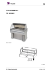
CD 3/4/5 Square
DIRECTIONS FOR USE
EN 2-1
www.frijado.com
9123798 / 1106
CD 3/4/5 Square
KEEP THIS USER MANUAL FOR FUTURE USE
© 2011 Fri-Jado BV, Etten-Leur, The Netherlands
We advise you to contact your supplier for the guarantee period and conditions. Further we refer to our
General Terms and Conditions for Sales and Delivery that are available upon request.
The manufacturer does not accept any liability for damage or injury caused by the failure to adhere to these
regulations or by not observing the usual caution or care in actions, operation, maintenance or repair
activities, even if not explicitly described in this manual.
As a result of constant commitment to improvement, it may happen that your unit deviates in detail from what
is described in this manual. For this reason the given instructions are only a guideline for the installation, use,
maintenance and repair of the unit referred to in this manual.
This manual has been composed with the utmost care. The manufacturer shall, however, not be held
responsible for any mistakes in this manual nor for any consequences thereof.
The user is allowed to copy this manual for his own use. Further all rights are reserved and nothing in this
manual may be reproduced and/or made public in any way.
en / 2-II
9123798 / 1106
CD 3/4/5 Square
Table of contents
1. Safety, hygiene and environment............................................................................2-2
1.1.
General............................................................................................................................................. 2-2
1.2.
CE-mark ........................................................................................................................................... 2-2
1.3.
Identification ..................................................................................................................................... 2-2
1.4.
Icons and symbols ........................................................................................................................... 2-3
1.5.
Safety measures .............................................................................................................................. 2-3
1.6.
Hygiene ............................................................................................................................................ 2-3
1.7.
Service, maintenance and repairs ................................................................................................... 2-4
1.8.
Materials used and the environment................................................................................................ 2-4
1.9.
Guarantee ........................................................................................................................................ 2-4
1.10. Accessories and options .................................................................................................................. 2-4
2. Description of the unit..............................................................................................2-5
2.1.
Operation.......................................................................................................................................... 2-5
2.2.
Intended use..................................................................................................................................... 2-5
2.3.
Parts ................................................................................................................................................. 2-6
2.4.
Technical specifications ................................................................................................................... 2-7
3. Install .........................................................................................................................2-8
3.1.
Unpack ............................................................................................................................................. 2-8
3.2.
Installation ........................................................................................................................................ 2-8
3.3.
Move................................................................................................................................................. 2-9
4. Operation.................................................................................................................2-10
4.1.
Switch on........................................................................................................................................ 2-10
4.2.
Switch off........................................................................................................................................ 2-10
4.3.
Check the set temperature............................................................................................................. 2-10
4.4.
Loading........................................................................................................................................... 2-10
5. Maintenance and cleaning .....................................................................................2-11
5.1.
Clean the condenser ...................................................................................................................... 2-12
5.2.
Clean the condensation evaporating unit....................................................................................... 2-12
6. Problems .................................................................................................................2-13
6.1.
en / 2-1
Replace the lamp ........................................................................................................................... 2-14
9123798 / 1106
CD 3/4/5 Square
1.
Safety, hygiene and environment
1.1. General
The manufacturer accepts no liability whatsoever for loss or injury caused by failure to strictly
adhere to the safety guidelines and instructions in this manual or due to carelessness during
installation, use, maintenance and repair of the unit referred to in this manual and any of its
accessories.
The unit may be operated by qualified and authorised persons only. Anyone who works on or with
this unit must be familiar with the contents of this manual and carefully follow all guidelines and
instructions. Never change the order of the steps to be performed.
The management must instruct the personnel on the basis of this manual and follow all instructions
and regulations.
1.2. CE-mark
The unit was built in accordance with European Guidelines and standards as specified in the CE
declaration delivered with your unit.
To ensure its proper functioning, use the unit solely in accordance with its purposes as stated in
EN 292-1. In this standard ‘intended use’ means the use for which this technical unit is suitable in
accordance with the technical specifications of the manufacturer inclusive of the directions in the
sales brochure.
In case of doubt it is the use which can be deducted from the construction, the model and the
function of the technical unit as being normal use. Operating the unit within the limits of its intended
use also involves following the instructions in the user manual and observing the inspection and
maintenance conditions.
1.3. Identification
The identification plate is located on the service side
and contains the following data:
• Name of the supplier or the manufacturer
• Model
• Serial number
• Year of manufacture
• Mains voltage
• Frequency
• Rated current
en / 2-2
9123798 / 1106
CD 3/4/5 Square
1.4.
Icons and symbols
1.4.1. Manual
In this manual the following icons and symbols are used:
Danger of personal injury or serious damage to the unit
Electric voltage
Hot surfaces
Additional information
Environmental aspects
1.4.2. Unit
The icons given below have been attached to the unit. Never cover or remove them. Immediately
replace or repair illegible or damaged icons.
Electric voltage
Lighting
Cooling
1.5. Safety measures
•
•
Never change the technical specifications mentioned in this manual.
Use the unit in a technically perfect condition only.
1.6. Hygiene
•
•
•
Prevent fresh raw vegetables or already prepared, cooled products from coming into contact
with raw meat products to avoid transmitting salmonella.
First thoroughly clean hands and/or tools that have touched raw meat.
Immediately remove products in damaged packaging from the equipment. Clean all
components that that have come into contact with products from damaged packaging.
en / 2-3
9123798 / 1106
CD 3/4/5 Square
1.7.
Service, maintenance and repairs
Regularly clean the unit to ensure its continued proper functioning.
WARNING
• Clean the unit daily. Keep to the maintenance intervals (see chapter 5).
• Follow the instructions regarding what to do in case of malfunction (see chapter 6).
WARNING
Do not clean the unit using a water hose.
This manual clearly makes a distinction between service, maintenance and repair
activities that can be carried out by the user and those which exclusively should be
carried out by qualified and authorised service engineers.
1.8. Materials used and the environment
1.8.1. Packaging material
All packaging materials are suitable for re-use. Do not dispose of the packaging
material with the industrial waste.
The following materials have been used:
• Untreated wood
• Cardboard
• Polyethylene foil
• Styropor
• Polypropylene tape
1.8.2. Remove
If required, the Fri-Jado supplier can advise on how to remove the unit. The Fri-Jado supplier can
also indicate which parts contain valuable substances and materials.
Treat the materials in accordance with the current local environmental regulations.
1.9. Guarantee
In case of unauthorised modifications in or on the unit, any liability on the part of the manufacturer
becomes null and void.
For contact data see the back of this manual.
1.10. Accessories and options
•
•
•
•
Sliding window for service model
Standard basis, available on legs or wheels
Condensation evaporating unit
Flat plate or adjustable frame
en / 2-4
9123798 / 1106
CD 3/4/5 Square
2.
Description of the unit
2.1. Operation
The refrigerated displays make use of a cooling unit in the basis and an evaporator.
This evaporator has been placed in the space beneath the flat plate in the basic model or beneath
the gastronorm pans of you have chosen for this option.
Ventilating fans lead the cold air on the upper side over the products and on the lower side along
the flat plate or the gastronorm pans. PL lamps have been placed into the top part. The cooling
and the lamps can be switched on separately.
The electronically controlled thermostat has been pre-programmed for the correct temperature in
the model you have chosen and for fully automatic defrosting at the factory. An automatic
condensation evaporating unit evaporates the released water. This provision is optional.
The sheeting of made of stainless steel SS 304.
You have chosen one out of two display options before setting up the display:
Flat plate
Depending on the model, the width of the flat plate is 964, 1298 or 1630 mm.
Dismountable panframe
The display area has been provided with a dismountable panframe in which 1/3 and behind that
1/1 gastronorm pans can be placed with a maximal depth of 65 mm immediately behind the front
window. Depending on the model there are either 3, 4 of 5 pans next to each other. Combinations
of other sizes of gastronorm pans are possible.
2.2. Intended use
WARNING
The refrigerated displays have been designed solely to keep packaged products cool
and to display them.
Any other use shall be considered to be not in conformity with the intended use. The manufacturer
accepts no liability whatsoever with regard to loss or injury that may be the consequence hereof.
The unit was built in accordance with European Guidelines and standards as specified in the CE
declaration delivered with your unit. Use the unit solely in technically perfect condition and in
conformity with the intended use described above.
en / 2-5
9123798 / 1106
CD 3/4/5 Square
2.3. Parts
2.3.1. Overview of the unit
A ControlSanel
&*ODVVSDQH
&/amps
&)ODWSODQH
&'HWDFKDEOHIUDPH
&(YDSRULVDWLRQXQLW
&)LOOLQJDUHD
&6HQVRUZDWHUOHYHO
A
B5
2.3.2. Control panel
A1 Indicator ON
A2 Indicator defrosting
A3 Display temperature
A4 UP key
A5 SET key
A6 DOWN key
A7 Cooling switch
A8 Lighting switch
A3
A4
A5
A6
A1
A2
When the cooling unit has been switched on,
the indicator lamp A1 is lit.
A2 is lit during automatic defrosting of the
evaporator.
Display A3 indicates the temperature in the
display.
A7
en / 2-6
9123798 / 1106
A8
CD 3/4/5 Square
2.4. Technical specifications
WARNING
See the identification plate for the correct specifications of the unit. The electrical
installation data may vary between different countries.
Dimensions Width
Depth
Height
Height with
basis
Weight Full-service
Full service
Basis
Voltage
Frequency
Max. rated current
Power to be supplied
Plug
CD 3 SQ
CD 4 SQ
CD 5 SQ
mm
mm
mm
1086
1058
1307
1419
1058
1307
1730
1058
1307
mm
1440
1440
1440
kg
kg
kg
195
200
37
230V 1N~
50
3.8
866
Two-pole
earthed plug
approx. 2.40
< 70
225
230
40
230V 1N~
50
4.6
1068
Two-pole
earthed plug
approx. 2.40
< 70
265
275
44
230V 1N~
50
5.2
1198
Two-pole
earthed plug
approx. 2.40
< 70
Hz
A
W
Cable length
m
Sound pressure
dB(A)
Product temperature
Full-service
3M1
3M1
3M1
class according to
NEN-EN 441-6
Standard accessories
user manual
user manual
user manual
Display (flat part)
Length
mm
964
1298
1630
Width
mm
608
608
608
Depth
mm
60
60
60
Maximum loading
mm
100
100
100
height
Refrigerant:
- As refrigerant has been used that complies with the environmental requirements applicable at the
time of manufacturing of the unit, the type and the filling weight are indicated on the cooling unit.
en / 2-7
9123798 / 1106
CD 3/4/5 Square
3. Install
3.1. Unpack
1.
2.
3.
4.
5.
Remove all parts from the unit.
Remove the foil from all metal parts.
Remove all packaging materials from the unit.
Check the unit for damage.
Make sure that all parts that belong to the model
you have ordered are present.
6. Read the manual before proceeding.
If any parts are missing or damaged, contact your supplier.
3.2. Installation
WARNING
Have an authorised installer install the wall socket.
WARNING
• There should be at least 50 mm clearance between the sides and other equipment
or walls.
• There should be at least 1 metre clearance between the service side and
other equipment or walls.
• Make sure that the openings in the basis are free.
• Do not position the unit near a doorway or a ventilation or heating unit.
• Position the unit flatly on a sufficiently sturdy base using a spirit level. Here take
the weight of the unit into account.
Follow the procedure below when storing a unit that will not be used for some time:
• Thoroughly clean the unit.
• Pack the unit dustproof.
• Store the unit in a dry place.
Make sure that the ambient temperature for the self-service model is not less than 10°C and not
more than 22°C with a maximum air humidity of 65%.
Make sure that the ambient temperature for the service model is not less than 10°C and not more
than 25°C with a maximum air humidity of 60%.
Find a suitable place for the unit. Points of interest:
• The products in the unit must be well visible.
• There must be sufficient room to operate and maintain the unit.
• Make sure that the unit is accessible for maintenance and service activities.
• Do not allow children on the service side.
• Contact your supplier before installing the unit outdoors.
• In connection with the danger of short circuit the unit is not suited for use in a rainy or very
moist environment.
en / 2-8
9123798 / 1106
CD 3/4/5 Square
WARNING
Have a recognised installer or service centre install the unit on an existing basis.
Provide a suitable discharge for the water that is released during use and cleaning
if an evaporating unit has not been opted for.
•
•
After installation, wait at least half an hour before switching on the unit. This in
connection with the stabilisation of the refrigerant.
1. Clean the inside, the removable parts and the accessories thoroughly with cleanser and water
before putting the unit into use.
2. After cleaning, wipe the unit with a cloth moistened with clean water to remove cleanser
residues and then dry the entire unit.
3. Attach all (optional) parts and/or accessories. For positioning the side windows and any sliding
windows, carry out steps 1 – 3. If you have chosen for a panframe, carry out steps 4 – 7 as
well.
4. Insert the plug into the socket.
5. Switch on the unit.
6. Let the unit cool for at least half an hour before filling it with products.
3.3. Move
Before moving the unit if it is a wheeled
model:
1. Switch off the unit.
2. Remove the plug from the outlet.
3. Remove pans containing a liquid product
from the unit.
4. Be careful when passing any corners or
thresholds while moving the unit.
en / 2-9
9123798 / 1106
CD 3/4/5 Square
4. Operation
4.1. Switch on
1. Switch on the cooling unit with switch A7.
2. Switch on the lighting with switch A8.
A8
A7
4.2. Switch off
1. Switch off the lighting with switch A8.
2. Switch off the cooling unit with switch A7.
4.3. Check the set temperature
A3
During use display A3 shows the temperature in the
unit.
1. Press the central key A5.
The display shows the set temperature.
The temperature measured in the unit appears again
after 20 seconds.
A4
A1
A2
A5
A6
4.4. Loading
Only load the unit with cooled products.
40 mm
Apply a maximum leading height of 40 mm above the
suction grid on the customer side. This gives a total
product height of 100 mm.
en / 2-10
9123798 / 1106
CD 3/4/5 Square
5.
Maintenance and cleaning
WARNING
• Remove the plug from the wall socket when carrying out maintenance and
cleaning activities.
• Do not clean the unit using a water hose.
WARNING
• Do not clean the unit using steel wool.
• Fri-Jado Clean may in some cases irritate a sensitive skin. Wear rubber gloves
when using it.
• Follow the instructions on the label of ‘Fri-Jado Clean’.
• Clean the control panel only with a damp cloth.
• First remove as much as possible spilled product. Use as little water as possible to
prevent the condensation evaporating unit from getting overloaded. Filthy water
and leavings will seriously foul the evaporating unit.
•
•
•
In view of hygiene and an optimal condition of the unit it is important to adhere to a
fixed cleaning pattern from the very beginning.
You can best remove meat residues and grease shortly after use of the unit.
Optimum cleaning results are achieved by using ‘Fri-Jado Clean’.
If possible, leave the unit open at night.
Item
Action
Interior
•
•
•
•
•
Exterior
•
Condenser
•
•
Condensation
evaporating unit
(if present)
•
Cleaning
frequency
Daily
Switch off the unit.
Take the products out of the unit.
Put the removable parts in a large basin with hot water and
soapsuds or Fri-Jado Clean. Let these parts soak overnight
and clean them the next day.
Clean the interior with hot soapsuds or Fri-Jado Clean.
After cleaning, dry the interior with a clean cloth. Make sure
no traces of cleaning agent are left behind.
Clean the exterior of the unit with a soft brush or sponge
Daily
and a little hot water with a mild detergent.
Dry the exterior with a cloth.
Clean the condenser of the cooling unit to ensure its
Monthly
continued proper functioning. See paragraph 5.1 for the
correct way of working.
Monthly
Clean the condensation evaporating unit to ensure its
proper functioning. See paragraph 5.2 for the correct way of
working.
Built-in units
In case of built-in units the situation is different, but cleaning the condenser and the evaporating
unit remains necessary.
en / 2-11
9123798 / 1106
CD 3/4/5 Square
5.1.
Clean the condenser
The condenser is accessible from the service side.
1. Remove the screws from the grid on the rear side of the right-hand leg and remove the grid.
2. The condenser is found in the left-hand side wall of the leg. Carefully clean this with a vacuum
cleaner and/or a soft brush.
3. Reposition the grid.
5.2.
Clean the condensation evaporating unit
The optional condensation evaporating unit is accessible from the customer side as well as from
the service side.
WARNING
Switch off the unit and unplug it from the mains socket outlet! Switching off the unit is
not enough, as the evaporating unit will still be live.
WARNING
The entire condensation evaporating unit is hot. Let it cool down before cleaning.
1. Switch off the unit and unplug it from the mains socket outlet!
2. Let the evaporating unit cool down.
3. Remove the front or rear plate between the legs of the basis, if present. In order to do this, lift
up the plate and move it towards you. The plate is released from its suspension points.
4. Clean the evaporating unit with hot water and vinegar.
5. Reposition the front or rear plate.
en / 2-12
9123798 / 1106
CD 3/4/5 Square
6. Problems
WARNING
• If the problem is not solved by consulting the table below, proceed as follows:
1. Switch off the unit.
2. Remove the plug from the outlet.
3. Contact your supplier/service agency. Make sure you have the following data at
hand: model and serial number.
• If the lead is damaged, immediately contact your supplier/service station.
All windows used in the unit are made of tempered glass. If windows must be replaced,
use the same material.
The required electric diagrams are to be fount in the electric area.
Item
Unit
Problem
Does not function.
Unit
The set temperature is not
reached within half an hour.
The temperature rises too
much.
Unit
Thermostat
Action
• Is the plug in the outlet?
• Is the power supply OK?
Check the fuses and the
earth leakage switch in the
meter cupboard.
• Are all switches in the
correct position?
• Close the sliding doors on
the service side (if present).
• Is the condenser clean?
• Have the required
environmental conditions
been met?
• Contact your
supplier/service agency.
Evaporating unit
The display shows the fault
message E1, E27, E29 or E30
of the symbols are flashing on
the left-hand side of the display.
•
Does not function.
Lamp
A lamp is defective.
en / 2-13
9123798 / 1106
•
Is the plug in the outlet on
the evaporating unit?
See paragraph 6.1
CD 3/4/5 Square
6.1.
Replace the lamp
2
1
1
1
The lamps are found in the upper cover. They are accessible via the service side.
1. Remove the plug from the outlet.
2. Remove the sliding windows from the unit (if present).
3. Dismount the window profile by removing the screws at the bottom side of the light cover (c).
4. Carefully slide the window out of the frame by moving it toward you and place it in a safe place
(d).
5. Remove the PL lamp by pulling it lengthwise out of the holder. Do this carefully to avoid
breaking.
6. Install the new PL lamp.
7. Carefully slide the window into the frame.
8. Mount the window profile and insert the screws.
9. Place the sliding windows into the unit.
en / 2-14
9123798 / 1106
CD 3/4/5 Square
en / 2-15
9123798 / 1106
CD 3/4/5 Square
Uw leverancier
Your supplier
Ihr Fachhändler
Votre revendeur
Su suministrador
Fri-Jado BV
Oude Kerstraat 2
4878 AA Etten-Leur
The Netherlands
Tel:
Fax:
+31 (0) 76 50 85 400
+31 (0) 76 50 85 444
www.frijado.com
/ 1-16
9123798 / 1106