1
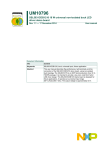
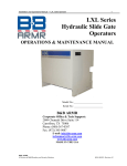
V6839_561_01_GB.fm Seite 1 Montag, 30. Juni 2008 1:17 13
GB
Connections, displays and operating
elements
| cores each of 0.8 mm diameter should be used in
Due to the possibility of a voltage drop, two
parallel (line cross-section > 0.5 mm2) in each
cable to the battery.
D
Emergency power supply REG-K
E
Operating instruction
3 Connect the mains voltage.
A1
A2
A3
4 Connect the power supply.
-
A
Bus
B
C
L2
+
+ -
L1 N PE
MTN6838..
L
N
-
+
L N PE
L
N
-
+
Necessary accessories
+ -
MTN683901
- +C
C
Art. no. MTN683901
A1 A2 A3 -
C
A
green LED: Mains voltage display
B
red LED: Error warning
C
yellow LED: Battery operating display
D
Operating state logging outputs
E
Battery connection (with cover)
L N PE
- +C
– Lead gel battery (art. no. MTN668991)
Accessories
– Power supply unit REG-K/160 mA
with emergency input (art. no. MTN683816)
– Power supply unit REG-K/320 mA
with emergency input (art. no. MTN683832)
½
– Power supply unit REG-K/640 mA
with emergency input (art. no. MTN683890)
For your savety
¼
DANGER
Risk of fatal injury from electrical current.
All work carried out on the device may only be
performed by skilled electricians. The countryspecific regulations and the valid KNX guidelines
must be followed!
½
CAUTION
Adjacent devices can be damaged. Only devices
with least basic insulation may be installed next
to the switch actuator.!
½
CAUTION
Safety clearance must be guaranteed as per
DIN EN 60664-1. A distance of at least 4 mm
must be maintained between individual cores of
the 230 V cable and the bus line.
½
The emergency power supply REG-K (referred to below
as the emergency power supply) secures the power
supply unit against mains failure. This ensures that the
bus voltage remains constantly available, as it is, when
necessary, supplied by a lead gel battery which is
connected to the emergency power supply.
A yellow display on the power supply unit indicates
when the bus voltage is being supplied by the
emergency power supply.
The display statuses (Battery, Error, Power) are also
available at outputs A1, A2, A3 and can, for example,
be recorded by the binary input REG-K/4x24
(art. no. MTN6448592).
CAUTION
No other device than one power supply
(e.g. art. no. MTN683890) that is approved for the
use with this emergency power supply should be
exclusive connected to the power supply
connection terminals (-, +, C)!
CAUTION
The connection cables to the power supply may
have a length of max. 1 m and and must be laid
out as a SELV cable! The connection cables to
the battery may have a length of max. 5 m and
and must be laid out as a SELV cable!
½
CAUTION
Only one DC 12V/6 - 18 Ah lead-gel battery
( art. no. MTN668991) should be attached to the
battery connection! The connection from the
lead-gel battery must be protected ba a seriesconnected circuit-breaker.
½
CAUTION
When handling and positioning batteries it is
essential to comply with the relevant safety rules
and regulations (incl. VDE 0510 Part 2 and Part 7)
to avoid the risk of injury!
MTN683901
MTN6838..
MTN668991
Emergency power supply REG-K
Power supply unit
Lead gel battery
| bus voltage, the emergency power supply can be
To provide extra security against any failure of the
connected up to another electrical circuit
(a different phase) than the power supply.
5 If necessary: Connect up a binary input.
½
CAUTION
In case of recording the display status with a
binary input:
You may only connect the binary input REG-K/
4x24 (art. no. MTN644892) in combination with
the power supply unit 24 V (art. no. MTN693003)
by the following connecting diagram!
+
L N PE
MTN
693003
|
Getting to know the emergency power
supply
- +
MTN668991
Installing the emergency power supply
The rechargeable lead-gel batteries requires no
maintenance and can be used in closed,
ventilated spaces at temperatures between -5 °C
and +45 °C. It is however not permitted to
position them in areas where there is a risk of
explosion.
+ -
+ -
MTN6838..
L N PE
- +C
Bus
+ -
MTN644892
E10V 0V E2
E3 0V0V E4
A1 A2 A3 -
+ -
MTN683901
L N PE
- +C
1 Insert the emergency power supply into the DIN
rail with the clamping spring facing down and
suspend it in the rail.
L2 L1 N PE
1
MTN683901
MTN6838..
MTN693003
MTN644892
MTN668991
2
- +
MTN668991
Emergency power supply REG-K
Power supply unit
Power supply REG, DC 24 V/0,4 A
Binary input REG-K/4x24
Lead gel battery
– Connect A1, A2, A3 of the emergency power suply
to E1, E2, E3 of the binary input.
3
2 Connect up a suitable battery on the yellow/white
battery terminal.
Put on the battery terminal cover.
– Connect „-“ of the binary output of the emergency
power supply to „-“ of the 24 V power supply unit.
– Connect „+“ of the 24 V power supply unit to „0“
of the binary input.
V6839_561_01_GB.fm Seite 2 Montag, 30. Juni 2008 1:17 13
VMains input:
Faults
Technical Data
No bus voltage in the connected line.
Mains input
Input voltage:
Mains
voltage
display
(Power,
green )
Error
warning
(Error,
red)
Battery
operatin
g display
(Battery,
yellow)
on
off
off
Mains voltage
available, battery
charging
on
on
off
Mains voltage
available, battery
voltage < 11 V.
on
off
on
Mains voltage
available, power
supply provided by
battery
on
on
on
Mains voltage
available, power
supply provided by
the battery and
output current too
high or battery
voltage < 11 V
off
off
on
No mains voltage,
power supply
provided by the
battery (battery
not charging)
off
on
on
No mains voltage,
power supply
provided by the
battery and output
current too high or
battery voltage
< 11 V
off
off
off
No mains voltage,
no battery voltage
Power consumption:
Output to power supply
unit (-, +, C)
Nominal current:
without battery approx.
300 mA
with battery approx. 640 mA
Short circuit current:
< 1.5 A
Stored energy time:
approx. 30 min (with 640 mA
and fully charged 7.2 Ah
battery)
Output/input to battery
(+, -)
Charging current:
max. 1 A
Power consumption:
< 50 W
Charging time:
Charging time
Display status output
Connection for binary input
(A1, A2, A3, -):
(art. no. MTN644892)
A1:
status mains voltage display
A2:
status error warning display
A3:
status battery operating
display
-:
joint potential
Compatible batteries: Lead-gel batteries in
accordance with DIN
Nominal voltage:
2V
Nominal capacity:
6 - 17 Ah
Output/input to battery
(+, -)
Charging current:
max. 1 A
Power consumption: < 50 W
Charging time:
(7,2Ah-/17Ah-battery)
approx. 10h/ 25h
Ambient temperature:
Operation:
Storage:
Transport:
Environment:
-5 °C to +45 °C
-25 °C to +55 °C
-25 °C to +70 °C
The device is designed for
use at an installation height of
up to 2000 m above sea level
(MSL)
Max. ambient humidity: 93 % relative humidity, no
dew formation
Connections:
Inputs, outputs:
Screw terminals for
0.5 - 2.5 mm2
single-core:
1.5 mm2 to 2.5 mm2
finely stranded with
core end sleeve::
1.5 mm2 to 2.5 mm2
Battery connection:
Battery terminal (yellow/
white). The battery should be
connected with four cores of
each 0.8 mm diameter (pairs
of two parallel), to provide a
line cross-section of at least
0.5 mm2 per cable
Dimensions:
90 x 72 x 65 mm (HxWxD)
Device width:
4 pitches
EC guidelines:
89/336/EEC
Schneider Electric Industries SAS
If you have technical questions, please contact the
Customer Care Center in your country.
www.schneider-electric.com
This product must be installed, connected and used in
compliance with prevailing standards and/or installation
regulations. As standards, specifications and designs
develop from time to time, always ask for confirmation
of the information given in this publication.
07/08
Key to emergency power supply displays
AC 110 - 230 V +/- 10 %,
50 - 60 Hz Power
consumption: 25 W
25 W
V6839-561-01
The mains voltage for both the power supply unit and
the emergency power supply has failed, and the battery
is discharged. The connected battery must be charged
to a high enough level to ensure reliable emergency
power supply. Refer to the technical data for the battery
to check how long the battery should be charged and
how long it can provide power.