1
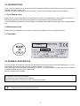
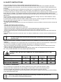
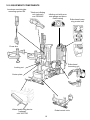
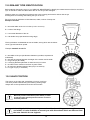
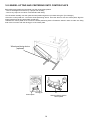
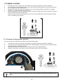
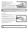
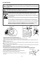
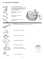
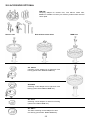
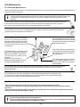
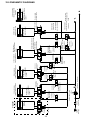
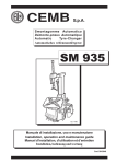
Operation Instructions
Original Instructions
Ed.10/13 Cod. 3019988
English
MATIC 750
EC DECLARATION OF CONFORMITY
CEMB S.p.a. - Via Risorgimento, 9 - 23826 Mandello del Lario (LC) - ITALY
do hereby declare on our own responsibility that the product:
Passenger Car Tyre Changer
Crossage EVO
which this statement refers to meets the following directive
86/217/CEE - 2006/42/CE 2006/95/CE - 2004/108/CE
EN 12100 - EN 60204-1
as well as the following:
The signature of this declaration of conformity is the person authorised
to provide for the technical literature file.
Mandello del Lario, 14/06/12
The model of the present declaration complies with directive EN ISO / IEC 17050-1
ROHS DECLARATION OF CONFORMITY
CEMB S.p.a. - Via Risorgimento, 9 - 23826 Mandello del Lario (LC) - ITALY
do hereby declare on our own responsibility that the product:
Passenger Car Tyre Changer which this statement refers to meets the following directive::
2011/65/EU (RoHS)
Scrapping must be made in accordance with the following directive:
2002/96/CE e 2003/108/CE (RAEE)
as well as with the national laws in force in the Country of Installation.
Mandello del Lario, 14/06/12
Remarks: for all the machines/appliances distributed from 01.01.2006 on, also all non-original spare parts
will have to meet the directive 2002/9/C E (RoHS).
RAEE DECLARATION OF CONFORMITY
CEMB S.p.a. - Via Risorgimento, 9 - 23826 Mandello del Lario (LC) - ITALY
do hereby declare on our own responsibility that the product:
Passenger Car Tyre Changer
which this statement refers to meets the following directive:
2002/96/CE e 2003/108/CE (RAEE)
Raccolta differenziata
This equipment is subject to the regulations foreseen by Directives 2002/96/CE and 2003/108/CE (RAEE) and therefore it
cannot be scrapped as a generic scrap material but through specific collection circuits; the symbol with “barred tank” marked
on the product refers to this prescription. Scrapping must be made in accordance with Directives 2002/96/CE and 2003/108/
CE (RAEE) as well as with the local Regulations in force in the Country of installation, the non-respect of the Directive is subject
to sanctions according to the national Laws of the Country of destination. Abandonment or wrong scrapping of the equipment
subject to Directive 2002/96/CE can cause serious damage to the environment.
The manufacturer is available, according to the Directive, to scrap the equipment; for this service, please contact the manufacturer
or your dealer.
Mandello del Lario, 14/06/12
2
CONTENTS
PAGE
CHAPTER
1.0
INTRODUCTION......................................................................................................................................................4
1.1 Tyre-Changer data...............................................................................................................4
1.2_DManufacturer data...........................................................................................................................4
1.3_Data plate.............................................................................................................................4
2.0
GENERAL DESCRIPTION....................................................................................................................4
3.0
SPECIFICATIONS.....................................................................................................................................5
4.0
DECALS PLACEMENT..........................................................................................................................................6
5.0
SAFETY INSTRUCTIONS....................................................................................................................7
6.0
SAFETY DEVICES.............................................................................................................................7
7.0
TraNSPORT.........................................................................................................................................................8
8.0
UNPACKING.......................................................................................................................................................8
9.0
InstallaTION....................................................................................................................................................9
9.1_Tyre-Changer site requirements........................................................................................................................9
9.2_PTyre-Changer placement and connections.....................................................................................................9
10.0 EQUIPMENT COMPONENTS...........................................................................................................................10
11.0 CONTROLS DESCRIPTION......................................................................................................................11
12.0 RIM AND TYRE IDENTIFICATION...............................................................................................................12
13.0 VALVE POSITION...............................................................................................................................12
14.0 WHEELS AND TYRES CLASSIFICATION.......................................................................................................13
14.1_Standard wheels.....................................................................................................................................13
14.2_Low-profiled tyre (UHP) wheels.....................................................................................................13
14.3_RUN-FLAT tyre wheels....................................................................................................................13
15.0 WDK RULES................................................................................................................................................13
16.0 POSITIONING AND CENTERING ONTO CENTER PLATE....................................................14
17.0 WHEEL LOCKING..................................................................................................................................15
17.1_Pneumatic locking..........................................................................................................................15
18.0 BEAD LOOSENING.......................................................................................................................................16
18.1_Upper bead..............................................................................................................................................16
18.2_Lower bead.........................................................................................................................................17
19.0 DEMOUNTING LOWER BEAD ON SPECIAL TYRES...................................................................................18
20.0 RIM AND TYRE MATCHING.................................................................................................................................18
21.0 TYRE DEMOUNTING..............................................................................................................................18
21.1_Upper bead demounting....................................................................................................18
21.2_Lower bead demounting.....................................................................................................................20
22.0 TYRE MOUNTING.........................................................................................................................20
22.1_Lower bead mounting............................................................................................................................20
22.2_Upper bead mounting..........................................................................................................................21
22.3_UHP and RUN-FLAT tyres mounting..................................................................................22
23.0 INFLATION.............................................................................................................................................23
24.0 STANDARD ACCESSORIES..................................................................................................24
25.0 OPTIONAL ACCESSORIES.....................................................................................................25
26.0 RE-POSITIONING................................................................................................................................27
27.0 STORAGE......................................................................................................................................27
28.0 SCRAPPING...............................................................................................................................27
29.0 OIL TREATMENT.......................................................................................................................................................27
30.0 MAINTENANCE...............................................................................................................................................28
30.1_Standard maintenance............................................................................................................28
30.2_Extraordinary maintenance............................................................................................28
31.0 TROUBLESHOOTING CHART............................................................................................29
32.0 WIRING DIAGRAMS...........................................................................................................................31
33.0 PNEUMATIC DIAGRAMS..........................................................................................................................32
34.0 SERVICE REPORTS................................................................................................................................34
3
1.0 INTRODUCTION
Thank you for purchasing one of our Professional Tyre-Changer designed for demounting and mounting operations on
standard, UHP and “run-flat” tyres.
To prevent accidents or damages to the tyre-changer, use only recommended procedures and accessories.
1.1 Tyre-Changer data:
Please refer to “Tyre-Changer Model” and “Serial Number” data on the Data-Plate (see sample below) to provide our
Technical Service Dept. with the necessary details for prompt assistance and spare-parts tracking.
In case of discrepancies between Tyre-Changer data on Data-Plate and this Manual, please refer to Tyre-Changer dataplate
only.
1.2 Manufacturer data:
Please check the “Declarations of Conformity” at page 2 of this Manual and Tyre-Changer Data-Plate
1.3 Data-plate:
LOGO
Model
2.0 GENERAL DESCRIPTION
The Tyre-Changer is intended for mounting and demounting most tyres with alloy or steel rim diameter from 12” to 30”
and standard, Run-Flat and UHP tyres with maximum diameter of 1.200 mm (47”).
The Tyre-Changer is NOT intended for demounting completely- or partially-inflated tyres, dirty tyres, nor for rim bending
or industrial wheels with split ring rims demounting.
All these operations are forbidden.
This Manual is part of this Tyre-Changer.
Use equipment only as described in this Manual.
Read and understand all instructions before operating this machine.
Keep this Manual in good conditions for further references.
Keep all instructions permanently with the unit.
4
3.0 SPECIFICATIONS
Connections:
-Electrical Feeding: 400V - 3Ph - 50/60 Hz (230V - 1Ph - 50/60 Hz motoinverter)
-Working air pressure: 8÷10 bar (116÷145 psi)
-Air-feeding pressure regulator set at 10 bar (145 psi) included
-Inflating air-pressure regulator set at 3,5 bar (50 psi) included
Working capacity:
-Rim diameter clamping: 10” to 34”
-Maximum rim width: 16” (410 mm)
-Maximum wheel diameter: 47” (1200 mm)
Motoinverter chuck details:
-Motor power: 0,75 Kw
-Maximum torque: 1200 Nm
-Clockwise rotation speed: 6÷12 rpm
-Working noise level: < 70 dB
Bead-Breaking units:
-Rollers BB cylinders power at 10 bar: 11770 N (1200 kg)
-Rollers BB maximum span: 670 mm (26”)
-Bead-pressing cylinder power at 10bar: 4218 N (430 kg)
Layout details:
-Minimum overall dimensions mm: 1180 x 1300 x 1770 H
-Net weight (optional accessories excluded): 425 kg
-Operating temperature range: min +5° C max +50° C (+41°÷+122° F)
Standard accessories (ref. page 24):
-WDK clamp with rubber protections
-Kit of plastic inserts for mounting tool
-Plastic lever
-Plastic protections for centering cone
-Rubber protections for chuck
-Plastic protections for chuck dowel
-Step-down ring
-Plastic protections for rim
Main optional accessories (ref. page 25):
-Inflating device for tubeless wheels
-FPM 456 flange for rims with reversed groove, blind wheels and special wheels
-Centering cones for LCVs rims
1130
2120
Packing details
Overall dimensions (mm)
Carton
1860
Gross weight 455 kg
(without optional
accessories)
8
19
60
Wooden pallet
11
3
118
5
5
4.0 DECALS PLACEMENT
Cod. 3033099
Cod. 3035727
Cod. 3033101
Cod.3005411
Cod. 3005416
Cod. 3019742
Cod. 3019739
Cod. 3033102
Cod. 3005742
Cod. 3033098
Cod. 3033097
Cod. 3033095
Cod. 3033096
Cod. 3008944
Cod. 3005410
Cod. 3001104
Cod. 3036268
Cod. 3000048
Cod. 3005414
Cod. 3019736
Cod. 3038028
Cod. 3038051
ATTENZIONE!
Replace any warning label immediately in case of damage or loss.
Do not operate the Tyre Changer in case of warning labels lack.
Do not hide any warning label by any mean.
Refer to the above mentioned codes for warning labels ordering.
6
5.0 SAFETY INSTRUCTIONS
The Tyre-Changer has to be used by qualified and authorised personnel only.
A qualified operator is someone who has fully understood the instructions described in the operation instructions
manual supplied by the manufacturer, who has been specifically trained and who is aware of safety standards at the
workplace.
It is essential to use proper service methods and change tyres in an appropriate and acceptable manner that does not
endanger your safety, the safety of others in the work of area or the equipment or vehicle in a safe manner.
It is assumed that, prior to using the Tyre-Changer, the operator has a thorough understanding of the wheels and tyres
being changed. In addition, it is assumed he has a thorough knowledge of the operation and safety features of the
Tyre-Changer accessories being utilized, and has the proper hand and power tool necessary to service the vehicle in a
safe manner.
Those in charge of using the machine shall not be under the influence of drugs, alcohol or other substances, which
could compromise their physical and mental work capabilities.
For greater safety, operators shall wear health & safety footwear, gloves, protection goggles and shall NOT wear any
form of clothing that could get caught up or restrict the operator’s movements.
The operator must be able to:
- read and ensure full comprehension of the use and maintenance manual to be able to use the machine correctly and
safely.
- read and understand the danger warnings.
- understand the characteristics of the machine.
- keep unauthorised people away from the work area.
- make sure the machine is started in full observance of all the applicable safety standards and rules.
- make sure all operators are familiar with the machine and how to use it safely and correctly.
- avoid touching moving parts or pressurised parts without first disconnecting the machine from the electrical and air
power supply.
- keep the operation instruction manual with care in an easily accessible place, so that it can be consulted whenever
needed.
The Tyre-Changer may exclusively be used by expert, specifically trained and authorised
personnel only.
- The use of the machine is forbidden to disabled operators if their disabilities may affect the safety of the working
operations
- Tampering or modifications to the equipment that are not authorised in advance by the manufacturer, relieve the lat
ter from all forms of liability as regards to damages deriving from or referable to such actions.
- Removal or tampering with the safety devices provides grounds to immediately cancel the warranty and involves
violation of European Safety Regulations and codes.
- The Tyre-Changer is equipped with informative and warning decals, which are designed and produced to last in
time. If they should deteriorate, user may request replacement decals.
IN CASE OF FIRE, USE ONLY DRY CHEMICHAL OR CO2 EXTINGUISHERS TO PUT THE
FIRE OUT.
WATER
extinguisher
FOAM
extinguisher
POWDER
extinguisher
CO2
extinguisher
DRY materials
FLAMMABLE liquids
OK
NO
ELECTRICAL equipment
NO
OK
OK
OK
OK
OK
OK
NO
OK
OK
6.0 SAFETY DEVICES
This Tyre-Changer is provided with the following safety devices in order to grant the operator’s safety.
-Pressure limit valve, installed into the Tyre-Changer to avoid inflations over 3,5 bar (50 psi) pressure.
-Pressure regulator with manometer, to limit the maximum system pressure to 10 bar (145 psi).
-(on Tyre-Changers equipped with “TubeLess inflating device”) Limit Valve, installed onto the air tank to avoid exceeding
11 bar (160 psi) pressure value.
Removing or tampering with safety devices immediately invalidates the guarantee and
it is in contravention of European Safety Rules.
7
7.0 TRANSPORT
The Tyre-Changer must be transported in its original packaging
The packaged machine has to be moved by mean of a fork lift of suitable capacity (500 kg min.). Please, insert the forks
as shown by the following picture “fig. 1”.
8.0 UNPACKING
Remove the protective cardboard, remove all fixing screw and free the Tyre-Changer from its original pallet.
Check the perfect condition of the machine, making sure that no part is damaged or missing, referring to the picture at
page 10.
If in doubt, please do not use the machine and get in touch with your Distributor for further steps.
Keep packing elements away from children.
All packing elements must be stored in the proper stocking areas.
Note: All the most delicate surfaces of the Tyre-Changer are coated by a special rust-proof oil.
Some oil traces may leak after coating procedure: please, remove them accordingly.
Gross weigth 455 Kg.
fig. 1
Lifting point
fig. 2
After tyre-Changer positioning, take of the lifting belt.
The machine must be moved by means of suitable capacity (fork-lift: 500 kg min. as per “fig. 1” or crane with liftingbelt: 500 kg min. as per “fig. 2”).
Lifting point
After having positioned the machine, in its final location,
release the safety pin against accidental tilting of the arm
(fig. 3) Put the pin together with the other standard accessories delivered with the machine, for any future need.
Fig. 3
8
9.0 INSTALLATION
9.1 Tyre-Changer site requirements
When choosing the place of installation be sure that it complies with
current safety-at-work regulations.
The Tyre-Changer must be connected to the main electric power supply
and the compressed air system. It is therefore advisable to install
the machine near these power sources.
The installation area must leave at least the room shown in picture
“fig. 4”, so as to allow all parts of the machine to operate correctly
and without any restriction.
1850
Fig. 4
9.2 Tyre-Changer placement and connections
Place Tyre-Changer onto a levelled-out, smooth and not slippery floor with a suitable load capacity.
No bolt down installation is required. In case of bolt-down installation, please refer to all 4 holes on the base of the machine,
drilling through 100 mm into the floor and using suitable bolts for fixing.
If the machine is installed outside it must be protected by a appropriate lean-to shed.
The electric network of the installation area must be provided with adequate earth plate and connected to an automatic
circuit-breaker (differential) set at 16 mA.
Should the Tyre-Changer be lacking in electric plug, the user must set one - at least 16 A and conform to the voltage of
the machine, in compliance with the regulations in force.
Before connecting the machine, please check that the characteristics of your networks
correspond to those indicated by machine’s data-label.
Even small jobs done on the electrical system must be carried out by professionally qualified
personnel.
The Manufacturer is not responsible for damages caused by electrical connection different
from the original indications.
Unplug the unit from electrical and pneumatic outlets before moving and servicing.
The pneumatic network of the installation area must be provided with min. 8 bar working
pressure outlet.
Connect the machine to the pneumatic network by means of the air fitting on oiler filter/
regulator installed onto the rear section of the machine.
9
10.0 EQUIPMENT COMPONENTS
Leverless mouinting/demounting system QX
TubeLess inflating
unit (optional)
cod. 9236665
Inflating unit with pressure gauge and pneumatic locking
Roller bead loosening control unit
Press Arm
Roller bead
loosening unit
Locking nut
Center plate
Wheel positioning device
(optional)
cod. 9237720
Pedal control units
10
11.0 controls description
6
14
20
22
23
7
8
9
10
11
13
12
19
16
17
21
15
5
18
4
1
3
2
1-Tilting pole pedal control
14-Deflation button (inflating: by pedal 4)
2-Clockwise and anticlockwise centre plate (ref. 15) rota- 15-Center plate
tion pedal control
16-Upper bead loosener roller
3-Wheel positioning device control pedal (optional)
17-Press arm control switch
4-Inflation pedal control
18-Lower bead loosener roller
5-Bead loosening rollers override engaging button
19-Operating arm control button
6-Bead loosener locking and override (ref. 5) activation 20-QX leverless system control switch
switch.
21-Upper bead loosener tilting control
7-Bead loosener releasing button.
22-Center plate pneumatic locking switch
8-Bead loosener “forward” movement button
23-Handle for disengagement of the Lever-Less mounting tool
9- Bead loosener “back” movement button
10-Upper bead loosening roller lifting button
11-Upper bead loosening roller lowering button
12-Lower bead loosening roller lowering button
13-Lower bead loosening roller lifting button
Any test must be operated with no tyre onto the machine.
Mind any component which could interfere with machine testing operations.
11
12.0 RIM AND TYRE IDENTIFICATION
Before starting demounting a tyre, it is of CRUCIAL IMPORTANCE to identify the measurements of the rim and of the
tyre, as well as to make sure that neither the rim nor the tyre are damaged.
Warning: these very important procedures have to be correctly performed to reduce risks of tyre
bursting while re-mounting and inflating the tyre on the rim.
Each rim bears an indication of their diameter, width, number of humps etc.
Example: 8Jx15H2
A = 8 nominal width of the rim in inches (1 inch= 25.4 mm)
B = J size of the flange
B
C = 15 nominal diameter of the rim
C
A
D = H2 double hump (anti bead removing edge)
D
8J x 15H2
Each tyre bears a considerable amount of details, among which are the dimensions, type and maximum speed.
Example: 205/65 R 15 91H TL
A
B
C D
EF
G
A = 205 width of the tyre (the distance between tyre sides, expressed in
millimetres)
B = 65 ratio percentage between the height of the section and its width
C = R type of tyre (R= radial)
D = 15 keying diameter(diameter of wheel and rim) in inches
E = 91 index of the maximum load born by each wheel
F = H maximum admitted speed of the tyre (H= 210 Km/h)
G = TL type of tyre (T= Tubeless)
13.0 VALVE POSITION
The picture on the right side symbolizes a rim as a clock face.
The valve positions described by the following working steps
always refer to the represented clock-face hours-marks.
Mind the position indications (hour-marks) in order
to put the valve and the pressure-sensor in correct
and safe positions.
It is strictly forbidden to mount tyres on rims with mismatching parameters (diameter
and width). It is also forbidden to mount tyres with dimensions which are different from
the ones stated in the car logbook.
12
14.0 TYRE CLASSIFICATION
14.1 Standard wheels
A “standard wheel” is a car wheel with steel or alloy rim, with center hole, drop centre close to the external border of the
rim and a standard tyre (not RUN-FLAT nor LowProfile).
14.2 Low-profiled tyres (UHP) wheels
Low profile tyres (UHP) are those in which the height (H) and the width (C) have a ratio lower than 0.5 (i.e. low profile
series 45 stands for a ratio of H/C = 0.45).
For tyres to be considered as low profile (UHP), they must also have a maximum speed code of equal to and/or higher
than V.
Maximum speed codes
Q= to 160 km/h
R= to 170 km/h
S= to 180 km/h
T= to 190 km/h
U= to 200 km/h
H= to 210 km/h
V= to 240 km/h
W= to 270 km/h
ZR= > 240 km/h
ZR(Y)= > 300 km/h
14.3 RUN-FLAT tyres wheels
RUN-FLAT tyres are those which allow to continue to drive the vehicle for a preset number of miles and at a preset
speed, even if they have no internal pressure. These parameters change from one manufacturer to another.
The market currently offers 2 different types of RUN-FLAT tyres:
- Those with reinforced sidewall (self-supporting) where, thanks to a different mix and a reinforced structure, the shoulder
of the tyre can bear the weight of the vehicle even when the internal pressure of the tyre is zero.
- Those with internal support which have a ring inside the rim that bears the sidewall of the tyre when there is no pressure
inside it. The internal support may be made of plastic (Pax-Sistem) or of metal (Support-Ring).
All the tyres which do not correspond to the above mentioned descriptions have to be considered as “standard tyres”.
This Tyre-Changer is able to handle all types of wheels with “standard” tyres, LowProfile (UHP) and RUN-FLAT tyres
with reinforced side.
RUN-FLAT tyres with internal support (PAX System or Support-Ring type) mounting/demounting procedures need special accessories to be used according precise dedicated instructions.
The mounting and demounting procedure is similar with “standard” tyre, LowProfile tyre (UHP) tyre or RUN-FLAT tyre
with reinforced side (self-supporting).
The bead-breaking procedure should be operated by shovel-blade bead-breaker with “standard” wheels – in order to
save time – while the rollers bead-breaking unit has to be used for all LowProfile (UHP) and RUN-FLAT tyres.
It is compulsory to follow the demounting/mounting instructions carefully, in order to avoid
tyre damages and the consequent risks for the vehicle and the passengers safety.
15.0 WDK RULES
WDK is a German certified body charged with the evaluation of tyre-changers functioning and their capability to perform
good and safe operations on RUN-FLAT and UHP tyres correctly, to avoid permanent and potentially dangerous damages to tyres.
In order to perform a correct demounting and mounting process, the following premises are strictly compulsory:
1. Guidelines knowledge - WDK literature provides all necessary guidelines for all tyre brands and models, including all
theoretical and practical instructions to avoid any possible damage to tyre, rim and pressure sensor.
2. Certified tyre-changer - This Tyre-Changer is WDK certified and fulfils all WDK requirements.
3. Qualified operator – The specific technical courses provide the operators with the necessary WDK guidelines and
service instructions. Dedicated WDK official courses are available to get the WDK diploma, when necessary.
13
16.0 WHEEL LIFTING AND CENTERING ONTO CENTER-PLATE
Before lifting and positioning the wheel onto the centre-plate, please:
- remove all weights from the rim by a proper tool carefully,
- remove any object or tool which could interfere with lifting.
-Put the wheel vertically onto the optional wheel positioning device (rim back facing the Tyre-Changer)
-Press the control pedal ref. 3 to lift the wheel-positioning device. Once the wheel is over the centre-plate, align the
wheel central hole to the centre-plate central hole.
-Release the control pedal fef. 3 to lower the wheel positioning device. Rotate the wheel in order to make one fixing
hole of the rim match with the driving pin of the centre-plate.
Wheel positionig device
(optional)
3
Driving pin
Centre-plate
Wheel positionig device
control pedal
14
17.0 WHEEL LOCKING
1.
2.
3.
4.
Insert the ring nut hub correctly (the cone plastic cover preserving the alloy rims from damages)
Turn the ring nut hub clockwise by hand until you find the exact coupling position, then press the hub and turn it clockwise by 90° to its full-stroke
Release the ring nut and make sure it raises by 0,40° (10 mm) approximately, otherwise turn it slightly clockwise or counter-clockwise lifting up the hub.
Make sure the plastic cone is in contact with the rim, perfectly centred with the drop-centre hole, the split of the nose matching up with the driving pin.
Tighten the ring nut so that it moves up to the cones and continue tightening so that the wheel is pushed firmly on the flange of the spindle.
17.1 Pneumatic locking system (optional)
If the tyre-changer is provided with the optional pneumatic locking system:
1.
2.
3.
4.
Insert the ring nut hub correctly (the cone plastic cover preserving the alloy rims from damages).
Turn the ring nut clockwise by hand until the exact coupling position, press the ring nut until its end-stroke and rotate the ring nut hub 90° by hand.
Release the ring nut and make sure thet it raises by 0,40° (10 mm) approximately.
Rotate the pneumatic locking switch onto the manometer panel to the locking position.
4
Make sure that rim is perfectly locked onto the cente-plate before starting any operation on the
wheel
15
18.0 BEAD LOOSENING
Make sure the tyre is completely deflated before starting any operation on the wheel.
-Remove all weights from the rim by a proper tool, paying attention not to damage the rim.
-Before starting any operation, please check the eventual presence of a pressure sensor. In positive case, it is prefe
rable to check its efficiency by a dedicated diagnostic tool.
-The bead loosening rollers are mounted on special ttilting supports to ease bead loosening on wheels with high profile
or soft tyres. This procedure is “Over Run”
“OVER RUN” PROCEDURE SHOULD NOT BE USED ON UHP AND RUN FLAT TIRES
Push down the hook
lever to release the
upper roller
Lift up the hook lever
to release the lower
roller.
18.1 Upper bead loosening
Check the correct centering and locking of the wheel onto the centre-plate.
Check that the upper disk arm is in the right position (step 1)
-to move the upper disk in its right position: unlock it from rest position by pressing the right lever
to the left (A), then lift the disk arm support by hand and lock it by pressing the right lever to the right (B)
Turn the switch 6 clockwise to free the bead-breaking unit and position it by handling the console, in order to let the
upper roller keep to 5 mm distance from the rim border, then lock the bead-breaking until by turning again te switch 6
clockwise.
Move the bead breaking arm onto the tyre by pressing buttons 8-9 an 10-11
Step 1
4
1
A
B
7
6
8
9
10
11
12
13
Pay attention to the valve sensor position during bead loosening steps.
Wrong movements of the upper roller could damage the sensor.
Avoid contacts between the lubricating paste and the valve
sensor, if any.
16
5
3
2
- Spin the centre-plate until the valve reaches position
at “3 o’clock” position.
- Lower the bead loosening roller until it touches the tyre
using controls 9 for lowering and 8 for lifting.
- Start spinning clockwise pressing pedal 22.
Note: the centre-plate can spin at 2 different speeds, according to
operator’s preferences
- While spinning the wheel, push the bead loosening upper roller down
under the edge of the rim, then press and hold down the “over-stroke”
function button 5 going on lowering the roller until the bead detaches
from the rim.
- As soon as enough space is available, grease both inner surface
of the rim and tyre bead carefully with a proper tyre lubricating paste.
Fase 2
Avoid contacts between the lubricating paste and the valve sensor, if any.
- Once the bead gets loosened, raise and move away the upper roller
by acting on button 10.
18.2 Lower bead
Keep the bead-loosening unit set up as for upper bead release: the lower roller is always aligned with the upper one,
at 5 mm distance from rim lower border already.
Lift the lower roller until it touches the lower bead using controls 13
for lifting and 12 for lowering.
Start spinning the wheel anticlockwise by pressing pedal 2.
- While spinning the wheel, push the lower roller up over the edge of
the rim, then press and hold down the “over-stroke” function button 5
going on lifting the roller until the bead detaches from the rim.
- As soon as enough space is available, grease both inner surface of
the rim and tyre bead carefully with a proper tyre lubricating paste.
Fase 3
Note: for a better control of the lower bead loosening
please refer to the dedicated mirror fitted onto
the Tyre-Changer main frame.
Press on the bead – never on the sidewall of the tyre while loosening the bead.
17
19.0 LOWER BEAD DEMOUNTING ON SPECIAL WHEELS
The lower bead of reverse drop centre rims with significant width may be hard to break with the lower disk.
In this case it is possible to use the upper bead-breaking disk to break the lower bead of the tyre:
-tilt down the upper disk arm support to its lower position (step 1) to get both upper-and lower-bead loosening disks at
the same tilt-angle (step 2);
-follow instructions as per chapter “18 BEAD LOOSENING” at page 16.
Step 1
Step 2
Upper bead loosening
arm
B
A
Lower bead loosening
arm
20.0 RIM AND TYRE MATCHING
Driving could be affected by vibrations caused by deformations of the rim and/or
of the tyre. To optimize the wheel-balancing, it is necessary to position the wheel
onto the Tyre-Changer again to bead-break and lubricate the rim and the tyre,
spinning the tyre around the rim to a proper position.
Both upper and lower rollers make this process easier, by gently holding the tyre
steady while the centre-plate spins the rim until the correct matching position.
21.0 TYRE DEMOUNTING
Once the bead loosening process is completed, and the wheel is already positioned onto the center-plate, check and
ensure its locking and centering.
21.1 Upper bead demounting
Mounting tool
in working
position
10 cm
- Turn the wheel until the valve is in the “1 o’clock” position
(roughly 10 cm - 4” distance from the mounting tool) in order
to avoid possible damages to the valve or the pressure
sensor.
4
1
3
2
Valve
18
-Press the pedal ref. 1 to position the mounting arm close to the wheel while driving.
The mounting arm by handling (fig. 5), lock it in position 1 by ref. 19 (fig. 5B) to lock the operating arm and the horizontal arm at the same time.
Automatically the mounting tool is moved up and away from the rim border to have a
clearance of approx. 2 mm when locked
- Lower the lever ref. 20 to insert the mounting tool between the bead and the rim edge. The mounting tool should penetrate enough to hook the tyre bead to let the operator complete the tyre demounting: spin slowly the wheel until the
mounting tool is positioned correctly.
A gentle pressure on the tyre sidewall by the upper roller could help the mounting tool positioning.
Fig. 5B
Fig. 5
19
19
Pos. 1
19
Pos. 2
Pos. 3
- As soon as the bead is perfectly hooked, lift the mounting tool by raising lever ref. 20 to pull out the bead.
To make the lifting easier set the tyre pressing unit at “6 o’clock” position and press the tyre side (fig. 6).
Get a further help by contemporarily lifting the lower tyre side by the lower bead-loosening roller (fig. 7).
20
Fig. 7
Fig. 6
- Press down on pedal ref. 2 to rotate the wheel clockwise until the entire bead is lifted from the rim
NOTE: rim and tyre must spin together as one.
- In order to help the bead coming out and reduce the stress to the tyre:
insert the plastic lever (as shown by picture aside) and spin the wheel
clockwise while lifting the tyre by the lower bead-loosening roller.
NOTE: The above mentioned action is compulsory for UHP and RUN-FLAT
tyres according to WDK rules.
To avoid damaging the valve and/or the pressure sensor, move the same to the “1 o’clock” position before inserting the tool in the dropp centre, operating the control lever 20.
19
21.2 Lower bead demounting
- Before pulling out the lower bead, spin the wheel to let the valve
reach “1” or “2” o’clock position in order to avoid possible
damages to the valve and the sensor - if any.
- Lower the lever ref. 20 to insert the demounting tool under the
lower bead. Raise the lever ref. 20 to lift the demounting tool and
the bead.
- Raise the lower bead loosening roller to lift the tyre until the lower
bead is 1 cm over the upper rim edge.
- In order to help the above mentioned operation, lift the tyre
manually at “2” or “3” o’clock position and insert the plastic lever
as per WDK rules for UHP and RUN-FLAT tyres.
- Spin the wheel clockwise until the tyre complete coming out.
- Press the pedal ref. 1 to move the mounting arm away, push the
rollers bead breaking unit away and pull out the tyre.
- Check the status of the pressure sensor - if any - and replace it if
necessary.
1
21.3 Tyre demounting by hand lever (LNL Lever-no lever system)
4
3
2
The Tyre-Changer is provided with a patented system which allows the use of a
standard steel lever to demount special wheels as:
- Wheels with very narrow rims,
- Wheels with very tender tyre sidewalls,
- Motorcycle wheels
The above wheels can not easily - or not at all demounted with the standard
LeverLess system.
In order to demount a tyre manually by a standard lever:
- pull the retractable claw up away from working area by lifting the handle ref. 23; up (fig. 1).
- lean the manual lever onto the fixed claw (fig. 2).
23 Handle
Fig. 1
Fig. 2
Retractable claw
Fixed claw
Once the manual demounting is finished, the standard position of the retractable claw can be restored by lowering the
handle ref. 23..
20
22.0 TYRE MOUNTING
- Check the rim and the tyre carefully, as per instructions at page 12 of this manual.
- If the rim has been moved, lock it again onto the centre-plate as per instructions
at page 16 of this manual.
- Lube 3 cm thickness along the whole internal surface of the rim and internal and
external surface of tyre beads.
Avoid contacts between the lubricating paste and the valve sensor, if any.
22.1 Lower bead mounting
- Put the tyre onto the centre-plate tilting the tyre at “12 o’clock” position in order
to make both upper and lower beads go under the upper rim edge.
- Press pedal ref. 1 to approach the mounting arm and position the mount/demount
head onto rim edge.
- Incline the tyre to the bottom at “3 o’clock” position, driving the lower bead to
the mounting head in order to put the lower bead over the mounting lip on the left side of
the head and under the demounting claw on the right side of the head.
- Rotate the wheel by pressing the pedal ref. 2, contemporarily press the tyre at “5
o’clock” position until the bead reaches the drop centre level. Keep the tyre pressed
until “8 o’clock” position while rotating
to complete the lower bead mounting.
22.2 Upper bead mounting
- Keep the mounting arm and the mount/demount head at working position, then put the tyre bead on the rim slightly
tilted down to “3 o’clock” position..
Bead correctly positioned
over the mounting lip.
OK
Bead correctly positioned
under the demounting claw
OK
Bead incorrectly positioned
causing bead damages
between the head lip
and the rim edge
Bead incorrectly positioned
- Press the button ref. 11 to lower the upper bead loosening roller until the upper bead reaches 3 cm level under the
rim edge.
- Make sure that the upper bead of the tyre rests on the left lip of the head and under the demountig claw on the
right side of the head.
- Press the pedal ref. 2 to rotate the wheel clockwise, contemporarily press the tyre
manually from “5 o’clock” position to force the bead at drop-centre position.
Keep it pressed while rotating up to “8 o’clock” position to complete
the upper bead mounting.
Make sure that rim and tyre always spin together.
- To make the upper bead mounting easier, use the tyre pressing unit by setting it at “5
o’clock” position and pressing lever ref. 17 to keep the bead at drop-centre level while
rotating up to “8 o’clock” position until the tyre complete mounting.
21
17
22.3 UHP and RUN-FLAT tyres mounting
- Some precise and careful operations are necessary to mount UHP and RUNFLAT tyres. It is compulsory to follow WDK rules to avoid permanent damages to
these tyres.
-Lower bead mounting can be performed as per standard instruction
at page 20 of this manual..
-Once the lower bead is mounted, keep the mounting arm and tool at working position and start WDK upper bead mounting procedure putting the tyre slightly tilted
down to “3 o’clock” position.
-Use the bead pressing clamp together with the proper rubber protection
( • steel rim, •• alloy rim,••• convex alloy rim) locking the clamp onto rim edge
with the valve at “3 o’clock” position.
If necessary, press the tyre side by the upper bead loosening roller to
help the correct positioning and locking of the clamp (fig. 1).
Fig. 1
-Keep the upper bead loosening roller at drop-centre level, spin slightly
to insert the pressing tool between the roller and the clamp and pressing
onto the tyre side until the upper bead reaches drop-centre level (fig. 2).
-Make sure that the upper bead of the tyre rests on the left lip of the mount head
and under the demounting claw on the right side of the head.
-Start spinning the wheel paying attention to the bead not going between
the rim edge and the bead loosening roller.
Fig. 2
While spinning, when clamp is roughly at “6 o’clock” position make sure
that the whole bead within this section is right inside the drop-centre.
-If this necessary condition for a correct mounting is not accomplished,
use the bead pressing unit pushing its tool onto the tyre side to insert
the bead into the drop-centre (fig. 3).
Act gently onto tyre sidewall during the above mentioned
process
- Go on spinning the wheel until the upper bead is completely mounted.
- Remove the clamp and the rubber protection by the help of the pressing unit.
Pull the pressing tool away and lift the roller away
from the working position by acting on button 10.
Press button 7 to move the bead sloosener from working position.
- Press the pedal ref. 1 to push the mounting arm up and move the roller bead
breaking unit away from working position.
- Keep the wheel locked onto the centre-plate during the inflating operations.
Read the inflating instructions at page 23 carefully.
- Once the tyre inflation is completed, unlock the wheel and bring it down
onto the floor, taking advantage of the optional wheel positioning unit.
22
Fig. 3
23.0 INFLATION
Tyres must be inflated with the utmost caution. The instructions below have to be read and
followed strictly.
This Tyre-Changer is not projected to protect operators and objects from accidental tyres explosions.
If tyre bead fails to fit in place at 3.3 bar pressure, it is necessary to repeat the bead loosening and
lubricating procedures before trying again to inflate the tyre.
If the tyre should burst or the rim should break under pressure, operators could be
seriously injured or even killed. Make sure the rim and the tyre are the same size.
Also check the state of wear of the tyre and the rim to make sure there are no defects before
starting to inflate.
Inflate the tyre with short blasts of air and check the pressure frequently while inflating.
This Tyre-Changer is automatically limited to an inflation pressure of 3,5 bar (50 psi).
The pressure regulator is NOT a safety device preventing explosions risks and damages.
NEVER EXCEED THE PRESSURE RECOMMENDED BY THE TYRE MANUFACTURER .
Keep hands and body as far away as possible from the tyre during inflation.
Pressure gauge
Inflating pedal
4
Deflation button
- Connect the inflation hose to the valve of the tyre.
- Make sure the rim and the tyre have the same diameter.
- Make sure the rim and tyre are sufficiently lubricated; lubricate if necessary.
- Press and release the inflation pedal ref. 4 continuously, checking the pressure on the gauge frequently until
the tyre
bead fits completely on the rim.
- Continue inflating to reach the pressure recommended by the tyre manufacturer. Always inflate in short blasts
and
always checking the pressure while doing so.
- Press the deflation button to deflate the tyre if, during inflation, the pressure exceeds the value recommended
by the tyre manufacturer.
NOTE: Sometimes, even blowing air into the tubeless tyre it may not inflate.
This problem may be solved by using the optional accessory TUBELESS INFLATING DEVICE
- In order to use the optional Tubeless Inflating Device:
press the safety valve against the rim border,
push the activating button onto the handle to blast air and press the
inflating pedal ref. 4 in order to feed the wheel valve.
- As soon as the tyre beading is completed, store the Inflating Device into
its housing.
23
Activating button
Safety
valve
24.0 STANDARD ACCESSORIES
Plastic bead pressing clamp with
extra plug for alloy rims with slippery edge.
To be used together with rubber protections
for mounting UHP and RUN-FLAT tyre
according to WDK rules.
Rubber protection for steel rims
(marked with • )
Rubber protection for alloy rims
(marked with •• )
Rubber protection for alloy convex rims
(marked with ••• )
Plastic lever.
To be used during tyre demounting according to WDK rules.
X2
Plastic protections for tool head.
X2
X2
X2
Centering cone plastic protection.
Centre-plate rubber protection.
Driving pin plastic protection.
Reduction ring for centre-plate.
To be used to fit particular alloy rims.
Rim edge plastic protection
24
25.0 Accessori Optional
FPM 456
Clamping adaptor for reverse rims, rims without centre hole,
BMWrims. Suitable to lock any rim /with any holes-number onto the
centre-plate.
Reverse rims
Rims without centre-holes
Art. 455/08
Centering cones adaptor kit for light-truck rims
locking (centre hole: Ø120 to Ø190 mm).
Art.458/08
Centering cones adaptor kit for light-truck rims
locking (centre hole: Ø190 to Ø220 mm).
Art. 611/11
Centering conical adaptor for steel rims locking
(centre hole: Ø75 to Ø120 mm).
Art. 659/11
Two-sides centering conical adaptor for steel
rims locking (centre hole: Ø75 to Ø145 mm).
25
BMW rims
9237720
Wheel positioning device
Art. 735/12
Tubeless tyres inflating device.
26
26.0 RE-POSITIONING
To re-position the Tyre-Changer in a new workplace: secure the moving parts (i.e. the bead pressing arms, etc.)
disconnect
all the power sources and install it again following all the instruction per chapter 9.0 of this manual.
Connections to power sources and connection & inspections of the safety systems must be carried out by
trained personnel.
27.0 STORAGE
If the tyre changer has to be stored away for extended periods of time:
- Disconnect the power sources.
- Empty the tanks containing operational fluids.
- Protect parts that could be damaged if dust should settle on them.
- Grease parts that could damage if they should dry up.
When re-commissioning the tyre changer:
- Follow the instructions given in chapter 9.0 of this manual.
- Replace any damaged parts, referring to the spare parts list - this to be carried out by skilled personnel.
28.0 SCRAPPING
If you should decide that the tyre changer can no longer be used, you are recommended to make it unusable by removing
the power supply connections, emptying the tanks and disposing of the fluids pursuant to current state and National
regulation.
The tyre changer is considered as heterogeneous waste and must consequently be split-up into parts made of similar
material (electrical parts, plastic parts and ferrous parts), which must be disposed of properly, according to current National
regulation.
WARNING: follow RAEE and ROHS Conformity Declaration rules for a correct disposal.
29.0 OIL TREATMENT
OIL IS POLLUTANT! DO NOT THROW AWAY OUTDOORS OR POUR ON THE GROUND
General precautions
- Avoid direct and prolonged contact with skin.
- Avoid the formation of oil mists in the air.
- Avoid splashing.
- Wear appropriate clothing, gloves and goggles to protect against oil splashes.
- Do not use greasy rags.
- Do not eat or smoke if your hands are soiled with oil.
First Aid instructions
- If oil is swallowed, do NOT induce vomiting but go immediately to the nearest medical centre with information
on the type of oil swallowed.
- If oil gets in eyes, rinse abundantly with water until irritation ceases, then go to the nearest medical centre.
- If oil comes into contact with skin, rinse abundantly with neutral soap and water. do not use solvents or irritant
products.
Disposing of used oil
Do not throw used oil away outdoors or pour it on the ground.
Drain into a suitable container and forward to specialised oil disposal centres, or hand it over to authorised
collection companies..
Oil spillages or leakages
Eliminate the cause of the leakage and stop the oil spillage from spreading using absorbent material. Clean
the area where the oil has spilled using degreasing detergents to prevent slipping and dispose of the waste
according to current state and Federal regulations.
Clean up the oil and send to special disposal centres according to current National regulations.
27
30.0 MAintenance
30.1 Standard Maintenance
Routine maintenance according to the following instructions is of crucial importance to ensure the correct operation and
lasting life of the Tyre-Changer.
Before starting any maintenance job, disconnect the electrical power supply by unplugging the machine
from the main electrical feeding and disconnect it from the pneumatic supply by shutting off the valve.
To release the compressed air from the circuit, press the inflation pedal (ref. 3) down for a few
seconds.
On daily basis, keep the machine clean eliminating any mould and dirt to ensure the perfect movement
of the slides and the tools and to grant the correct functioning of all centering and locking systems.
Do not clean with compressed air, which can blast dirt between moving parts.
On daily basis, check for worn or damaged plastic and rubber inserts and protections that should be
replaced to prevent damages to rims and tyres.
Every 2/3 days, check the oil dropping
into the cup (1 drop every 4/5 activations of the bead pressing tool or of the
bead loosening systems). If necessary,
turn the screw on the top of the cup by
a screwdriver.
On periodical basis, check the oil level
which has to keep between MIN and
MAX refs. If necessary, unscrew the
cup and top-up by adding oil for
pneumatic
systems in class ISO HG (i.e.
ESSO Febis K32; MOBIL Vacouline
Oil 1405; KLUBER Airpress 32).
For a long lasting correct functioning of
the 10bar pressure limit device, ensure
that the drain level doesn’t exceed the
MAX DRAIN indication
Max
Drain
If necessary, drain the condensation by
turning clockwise the drain tap. (keep
the pneumatic feeding on to perform
this adjustment).
On monthly basis, unplug the machine
from pneumatic feeding and remove
the filter cup to clean it from possible
solid impurities.
On periodical basis, clean the sliding guides of the bead loosening carriage by naphtha and lube them
by oil or proper grease. Perform the same cleaning and lubricating actions on every junction and
mechanical sliding.
On periodical basis, check the tensioning of centre-plate rotation driving belt. If necessary, use
a 13mm wrench to loosen the fixing bolts of the motor support plate, then adjust the belt tension
by acting on the tensioning screw and tight the fixing bolts.
30.2 Extraordinary maintenance
- Non-routine maintenance must be carried out by factory authorized personnel ONLY.
- Defective parts should be exclusively replaced with genuine spare parts by factory authorized service
personnel.
- After 5 years from installation date, the Tyre-Changer must be serviced in all its main components to grant its
correct functioning and the operators safety.
The Manufacturer is not responsible for claims due to non-original spare parts or for damages caused
by removal and tampering to the safety devices.
Removal or tampering with the safety devices (max. pressure valve – pressure regulator) represents a
breach of European Regulations for Workplace Safety.
28
31.0 TROUBLESHOOTING CHART
PROBLEM
CAUSE
ISOLUTION
Centre-plate does not rotate
1) Missing electrical feeding
2) Power cord missing or not plugged
correctly
3) Fuses blown or differential disabled
4) Drive belt loosened or damaged
5) Motor pulley loosened
6) Micro-switches cam-shaft
disconnected from pedal
7) Motor damaged or defective
1) Turn power on
2) Check cord or plug in
3) Replace fuses or enable
differential
4) Tighten or replace drive belt
5) Tighten pulley by proper
screw
6) Reconnect or replace shaft
7) Replace motor
Chuck turns at one speed only or in one
direction only after pedal is released
1) Foot pedal connection out of
adjustment or not installed
correctly
2) Micro-switches fixing screws
loosened or missing
3) Micro-switch damaged or defective
4) Pedal return spring broken or
loosened
1) Adjust foot pedal
2) Check screws tightening or
replace screws
3) Replace micro-switch
4) Replace return spring
Chuck rotating motor turns at one speed
only or in one direction only
1) Micro-switch damaged or defective
2) Micro-switch cable unplugged
3) Motor damaged
4) Motor cables unplugged
1) Replace micro-switch
2) Check and connect microswitch cable
3) Replace motor
4) Check and connect motor
cables
Chuck rotating motor turns at one speed
only or in one direction only
1) Micro-switch damaged or defective
2) Micro-switch cable unplugged
3) Motor damaged
4) Motor cables unplugged
1) Replace micro-switch
2) Check and connect microswitch cable
3) Replace motor
4) Check and connect motor
cables
Chuck turns but wheel stays still
1) Wheel locking nut not holding
2) Driving pin not holding
1) Secure locking nut correctly
2) Position driving pin correctly
Bead loosening unit do not move vertically or move slowly
1) Pneumatic supply missing
2) Control valve broken
3) Pilot valve broken or defective
4) Cylinder seal broken
5) Mufflers obstructed
6) Control valve air hose squeezed
1) Check line pressure
2) Replace control valve
3) Replace pilot valve
4) Replace cylinder seal
5) Clean or replace muffler
6) Check or replace air hose
Bead loosening rollers reach working
position but do not perform overrun movement
1) Pneumatic supply missing
2) Control valve broken or defective
3) Cylinder seals broken
4) Overrun pilot valve broken
5) Pilot valve broken or defective
1) Check line pressure
2) Replace control valve
3) Replace cylinder seals
4) Replace overrun pilot valve
5) Replace pilot valve
Roller bead loosening unit do not move
horizontally
1) Locking/unlocking valve broken
1) Replace valve
LeverLess mounting tool doesn’t move
vertically
1) Pneumatic supply missing
2) Pneumatic supply hoses broken or
squeezed
3) Control valve broken
4) Mufflers obstructed
5) Cylinder seal broken
1) Check line pressure
2) Replace pneumatic supply
hoses
3) Replace control valve
4) Clean or replace mufflers
5) Replace cylinder seals
29
PROBLEM
CAUSE
ISOLUTION
Wheel lifter tool doesn’t move or it moves
slowly
1) Pneumatic supply missing
2) Control valve broken
3) Mufflers broken or unadjusted
4) Cylinder seal broken
1) Check line pressure
2) Replace valve
3) Clean, adjust or replace
mufflers
4) Replace seals
Mounting arm doesn’t move or it moves
slowly or too fast
1) Pneumatic supply missing
2) Mufflers obstructed
3) Mufflers unadjusted
4) Cylinder seal broken
1) Check line pressure
2) Clean or replace mufflers
3) Adjust mufflers
4) Replace cylinder seals
Mounting arm doesn’t keep the memorized position
1) Pneumatic supply missing
2) Knob control valve broken
3) Pilot valve broken
4) Cylinder seal broken
5) Locking plates worn
1) Check line pressure
2) Replace knob control valve
3) Replace pilot valve
4) Replace cylinder seals
5) Adjust or replace plates
Mounting arm stays locked in a memorized position
1) Pedal activating valve broken
1) Replace activating valve
Bead loosening unit doesn’t react to control pedal while cylinder shaft slides
1) Pneumatic supply missing
2) Bead loosening cylinder valve
broken
3) Mufflers obstructed
4) Bead loosening cylinder seal
broken
1) Check line pressure
2) Replace cylinder valve
3) Clean or replace mufflers
4) Replace cylinder valve
Shovel blade bead loosening unit doesn’t
keep the memorized position
1) Arm locking cylinders defective or
pneumatic supply missing
2) Bead loosening control knob valve
broken
3) Cylinder seal broken
4) Locking plates worn
1) Replace locking cylinders or
check line pressure
2) Replace control knob valve
3) Replace cylinder seal
4) Adjust or replace plates
Bead pressing device doesn’t react to
controls or it moves irregularly
1) Pneumatic supply missing
2) Control valve broken
3) Mufflers obstructed
4) Cylinder seal broken
1) Check line pressure
2) Replace control valve
3) Clean or replace mufflers
4) Replace cylinder seal
Mounting tool touches the rim during
working steps
1) Locking plates unadjusted or
defective
2) Wheel locking nut loosened
1) Adjust or replace locking
plates
2) Tight locking nut correctly
Inflating device doesn’t work
1) Pneumatic supply missing
2) Pedal control valve broken
3) Pressure limit valve broken
1) Check line pressure
2) Replace control valve
3) Replace pressure limit valve
30
32.0 WIRING DIAGRAMS
Motoinverter wiring diagrams (Two speed clockwise-1 speed anticlockwise)
Power supply line
LINEA ALIMENTAZIONE
230V 1Ph 50/60Hz
Motoinverter
SCATOLA MOTORE
MOTORE 1HP
A CARICO
DELL'UTENTE
Imax=16A
Installation
by the user
L6-20P
Plug
AZIONAMENTO
Electronic
board
BLU
SPINA NEMA
NERO
MARRONE
Id=30mA
V
W
U
1
N
2
3
4
L
INTERRUTTORE
S1
FUNZIONE
S1
1° VELOCITA' AVANTI
S2
2° VELOCITA' AVANTI
S3
VELOCITA' INDIETRO
Switch
Function
S1
Slow speed
clockwise
S2
Fast speed
clockwise
S3
Speed counterclockwise
31
S2
BIANCO
White
GRIGIO
Grey
Pedal switch
GIALLO
Brown
PEDALIERA 12V
Yellow
Connettori
Molex Minifit
MARRONE
Plug and
sockets
S3
32
Air supply
Sorgente
Lifter valve
Valvola
Sollevatore
Valvola abilitazione
salita stallonatore
inferiore
Bead loosener
lifting cylinder
di Max
Lubrificatore
Bead loosener
lowering cylinder
Valvola abilitazione
discesa stallonatore
inferiore
inferiore
Valvola abilitazione
discesa stallonatore
superiore
Bead loosener
left movement
valve
Valvola abilitazione
traslaz.SX stallonatore
Valvola selezione
bloccaggio movimento
stallonatore
Bead loosener
loocking movement
selecting valve
Valvola abilitazione
traslaz.DX stallonatore
Bead loosener
right movement
valve
Valvola traslazione
orizzontale stallonatore
Horizontal movement
bead loosener cylinder
Bead loosener
Cilindro traslazione
orizontal translation
orizzontale stallonatore cylinder
Bead loosener
Bead loosener lowering cylinder
lifting cylinder
superiore
Valvola abilitazione
salita stallonatore
verticale stallonatore
superiore
Valvola traslazione
Bead loosener
vertical translation
cylinder
Cilindro traslazione
verticale stallonatore superiore
Lubricator
Valvola traslazione
verticale stallonatore
Bead loosener
vertical translation
cylinder
Cilindro traslazione
verticale stallonatore inferiore
Limiting valve Valvola
Rubinetto
Ingresso aria
Lifting
cylinder
Cilindro
Sollevatore
Optional
Overrun bead
loosener valve
A
05.1
B
05.1
Horizontal movement
bead loosener locking
cylinder
Z8
Cilindro bloccaggio
traslazione orizzontale
stallonatore
Valvola selezione
Bead loosener
movimento over corsa stroke selection
stallonatore
valve
Valvola abilitazione
over corsa stallonatore
Overrun bead
loosener valve
Valvola movimento
stallonatore over corsa
Overrun bead
loosener cylinder
stallonatore over corsa
Cilindro movimento
33.0 PNEUMATIC DIAGRAMS
33
04.14
04.15
A
B
Removable
tool valve
Valvola
utensile
estraibile
Removable
tool cylinder
Cilindro
utensile estraibile
Cilindro
Press arm
cylinder
press arm
Bead loosener
hook valve
arpione carrello
stallonatore
Valvola
Press arm
valve
Valvola
press arm
Bead loosener
hook cylinder
Lock-unlock
pole valve
Valvola
sbloc.\bloc.palo
lifting cylinder
Cilindro
Cilindro
sollevamento braccio operante
arpione carrello
Operating arm
stallonatore
sbloc.\bloc.palo
Cilindri
Lock-anlock
pole cylinder
2
Quick
discharge
valve
Valvola
scarico rapido
1
3
Tilting pole
valve
ribaltamento
palo verticale
Valvola
Valvola
bloccaggio
pneumatico
Locking
valve
Deflating
button
Pulsante di
sgonfiaggio
(51 psi)
3,5 bar
Inflation
valve
gonfiaggio
Valvola di
Cilindro Locking
bloccaggio cylinder
pneumatico
di gonfiaggio
Inflation max
Dispositivo controllo
pressure control
pressione massima
device
OPZIONALE
Cilindro
Tilting pole
ribaltamento cylinder
palo verticale
Tubo di
gonfiaggio
Inflation
hose
34.0 SERVICE REPORTS
All the operations made on the machine in the course of time must be reported herebelow so as to have an
updated situation of the efficiency of the machine.
The user must carry out both cleaning and greasing operations according to the instructions given in this
manual.
Any operation concerning the replacement of parts is strictly reserved to authorized and trained staff.
Date
Signature
Intervention
Replacements
Notes
Date
Signature
Intervention
Replacements
Notes
Date
Signature
Intervention
Replacements
Notes
34
Date
Signature
Intervention
Replacements
Notes
Date
Signature
Intervention
Replacements
Notes
Date
Signature
Intervention
Replacements
Notes
Date
Signature
Intervention
Replacements
Notes
35