1
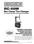
M806A Motorcycle/ATV Tire Changer INSTRUCTION MANUAL READ THIS ENTIRE MANUAL BEFORE OPERATION BEGINS Safety Instructions Operating Instructions Installation Instructions Maintenance Instructions READ these instructions before placing unit in service. KEEP these and other materials delivered with the unit in a binder near the machine for ease of reference by supervisors and operators. VERSION:B 0 RECORD THE FOLLOWING INFORMATION WHICH IS LOCATED ON THE SERIAL NUMBER DATA PLATE. Serial Number: _________ Model: Factory Code: Technical Standard Code Q/YGM001--2006 This product has passed the examination. Operators Protective Gear and Equipment Personal protective equipment helps make tire changing safer. However, equipment does not take the place of safe operating practices. Always wear durable work clothing during tire service activity. Shop aprons or shop coats may also be worn, however loose fitting clothing should be avoided. Tight fitting leather gloves are recommended to protect operator’s hands when handling worn tires and wheels. Sturdy leather work shoes with steel toes and oil resistant soles should be used by tire service personnel to help prevent injury in typical shop activities. Eye protection is essential during tire service activity. Safety glasses with side shields, goggles, or face shields are acceptable. Back belts provide support during lifting activities and are also helpful in providing operator protection. Consideration should also be given to the use of hearing protection if tire service activity is performed in an enclosed area, or if noise levels are high. WARNING Failure to follow danger, warning, and caution instructions may lead to serious personal injury or death to operator or bystander or damage to property. Do not operate this machine until you read and understand all the dangers, warnings and cautions in this manual. For additional tire, wheel, and/or inflation information contact the following: RUBBER MANUFACTURERS ASSOCIATION 1400 K Street N.W. Washington, DC 20005 (202) 682-4800 www.rma.com TIRE GUIDES, INC. The Tire Information Center 1101-6 South Rogers Circle Boca Raton, FL 33487-2795 (561) 997-9229 www.tireguides.com 1 Owner’s Responsibility To maintain machine and user safety, the responsibility of the owner is to read and follow these instructions: Follow all installation instructions. Make sure installation conforms to all applicable Local, State, and Federal Codes, Rules, and Regulations; such as StateandFederalOSHARegulationsandElectrical Codes. Carefully check the unit for correct initial function. Read and follow the safety instructions. Keepthemreadilyavailableformachineoperators. Make certain all operators are properly trained, know how to safely and correctly operate the unit, and are properly supervised. Allow unit operation only with all parts in place and operating safely. Carefully inspect the unit on a regular basis and perform all maintenance as required. Serviceandmaintaintheunitonlywithauthorized or approved replacement parts. Keep all instructions permanently with the unit and all decals on the unit clean and visible. This tire changer comes with a very detailed and easy to understand instruction manual. This manual assumes that the customer has used a wheel clamp style tire changer previously, or has operators that have operated a wheel clamp style tire changer. If this is your first tire changer purchase and you have not operated a wheel clamp style tire changer, it is strongly recommended to have a person/trainer who is familiar with this style of tire changer train you in the operation. This tire changer is very similar to many other tire changers on the market. The distributor that sold this unit will be glad to give you a demonstration session at their location or guide you to someone who can provide a service call to your location for training (a service charge would apply). The distributor also offers telephone technical support and trouble-shooting suggestions as needed. This does not take away from the responsibility you have to read and understand this complete manual. This responsibility is no different than when you purchase an automobile. The automobile dealer assumes you know how to operate and drive a motor vehicle. Safe operation is your responsibility and the dealer assumes you know how. Seek training as needed. DANGER EXPLOSION HAZARD – NEVER EXCEED 40 PSI WHILE SEATING BEADS Explosion Hazard Never inflate tire above manufacturer’s recommended pressure after bead is seated. 2 WARNING This machine is only applied to mount, demount and inflate the tire in the specified scope and not for any other purpose. The manufacturer will not be responsible for the damage or injury caused for the operation not properly and out of the range. NOTE This machine should be operated by the special trained qualified personnel. When operating, the unauthorized personnel will be kept far away from the machine. Please note the safety label stuck on the machine. Operators should wear safety protective facilities such as working suit, protective glasses, and ear plug and safety shoes. Keep your hands and body from the movable parts as possible as you can. Necklace, bracelet and loosen clothing may cause dangerous to the operators. Tire changer should be installed and fixed on the flat and solid floor. The more than 0.5m of distance from the rear and lateral side of the machine to the wall can guarantee the perfect air flow and enough operation space. Do not place the machine in the site of high temperature, high humidity, and dust and with flammable and corrosion gas. Without the permission from the manufacturer, any change on the machine parts will cause injury/damage to the machine/operator. Pay attention that the tire changer should be operated under the specified voltage and air pressure. If you want to move the tire changer, you should under the guidance of the professional service personnel. Notice: During operation, one operator is required for working on the wheel weighing below 25kg, two operators required for the 25-50kg wheel, and wheel lifting equipment for wheels heavier than 50kg. 3 SAFETY LABEL INSTRUCTION Keep your hands far from tire when operation Carefully read operation manual before operation When operation , wear the protective facilities electrical shock! When rapid ensure inflation, the wheel clamped. Do not reach any part of your body under the demount tool. When operation, do not wear long hair, loosen clothing and jewelries.. When breaking bead, the bead Breaking blade will quickly move leftwards. When operation, do not reach y our hand under the falling objects. Note: when press the tire, the opened clamp cylinder may injury the hand of the operator. Remember, do not touch the side Wear the goggle wall of the tire. When clamping the rim, do not Reach your hand or other parts Of the body in between the clamp Read the user manual & the rim. 4 Do not stand behind the column to Avoid the column from injuring the persons when swing. Wear the gloves SAFETY LABEL POSITION DIAGRAM Pay attention to keep the safety labels complete. When it is not clear of missing, you should change the new label. You should let the operators see the safety labels clearly and understand the meaning of the label. 5 CONTENT CHAPTER Ⅰ BRIEF INTRODUCTION 1.1BRIEF INTRODUCTION………………………………………………………………………………………………….6 1.2EQUIPMENT OVERALL DIMENSION (EXCLUDING THE ASSSISTANT) ……………………………………….6 1.3 TECHNICAL PARAMETER………………………………………………………………………………………………6 1.4 APPLICATION SCOPE……………………………………………………………………………….…………………..6 1.5ENVIRONMENT REQUIREMENT …………………………………………………………………………..…………..6 CHAPTER Ⅱ CONFIGERATION AND OPERATION…………………………………………………………………….6 CHAPTER Ⅲ INSTALLATION AND CALIBRATION…………………………………………………………………….7 3.1 OPEN PACKAGE CARTON……………………………………………………………………………………………..7 3.2 INSTALLATION …………………………………………………………………………………………………………..7 3.3AIR SOURCE INSTALLATION………………………………………………………………………………………….9 CHAPTER Ⅳ DEMOUNT AND MOUNT TIRE…………………………………………………………………….….….10 4.1 DEMOUNT TIRE……………………………………………………………………………………………….…….….10 4.2 MOUNT TIRE………………………………………………………………………..…………………………….…….11 4.3 INFLATION…………………………………………………………………………………………………………..…..11 CHAPTER Ⅳ MAINTANENCE AND REPAIR………………………………………………………………………...…12 CHAPTERVI TRANSPORTATION…………………………………………………………………………………..…13 CHAPTER Ⅳ ELECTCTRICAL AND PENUMATIC DRAWING……………………………………………………….14 CHAPTER Ⅳ GENERAL TROUBLESHOOTING AND SOLUTION ………………………………………………….15 CHAPTER IXPACKAGE LIST &OPTIONAL ACCESSORIES…………………………………………………………17 APPENDIX……………………………………………………………………………………………………………………18 6 CHAPTER Ⅰ BRIEF INTRODUCTION 1.1BRIEF INTRODUCTION This series of equipment is the tire changer with fixed column and rocker arm tire changer. It is suitable to mount, demount and inflate all types of motorcycle tires with tube & tubeless. The operation is easy, convenient, safe and reliable. The model is M806A. 1.2EQUIPMENT OVERALL DIMENSION Model M806 Height Length Width Net Weight (mm) (mm) (mm) kg 1750 860 750 175 FIG1 CHAPTER Ⅱ CONFIGERATION AND 1.3 TECHNICAL PARAMETER Operational Pressure:8-10bar Motor:50Hz ±1% 400V±1% OPERATION 0.75kW Know Your Unit - Compare this illustration with the unit before placing it into service. Maximum performance and safety will be obtained only when all persons using the unit are fully trained in its parts and operation. Each user should learn the function and location of all controls. Prevent accidents and injuries by ensuring the unit is properly installed, operated, and maintained. Turntable Rotation Speed:6rpm Noise:<75dB Note: An over-voltage protection device is needed for the connection with power supply 1.4 APPLICATION SCOPE model max. wheel max. wheel rim diameter diameter width (external clamping) 806 960mm(37″) 254mm(10″) 6″~24″ 1.5 ENVIRONMENT REQUIREMENT ambient temperature 5℃~45℃ relative humidity 50%@40C -90%@20C sea level max.1000m without dust and flammable and explosive gas The operation space around the machine wills not smaller then the indicated in FIG1 If the machine is installed outdoors, it must have the protective shed to avoid being exploded to the rain and sunlight. It is forbidden to use in the site with the flammable gas! FIG2 7 3.1.2Keep the package material far away from the 1-vertical shaft spring 2 - rocker arm 3- hexangular shaft 4- demount tool 5- claw 6- turntable 7- turntable cylinder 8- operation panel 9- clamp pedal 10- press tire pedal fix according to the FIG5. Remove the bolt, elastic 11- turntable pedal 12- crowbar washer and plate 13- blade 14-bead breaking cylinder 15- bead breaking arm 16- air source 17- lock handle 18 - column working site and deal with it properly. 3.2 INSTALLATION 3.2.1After un-package the package carton, take out accessory boxes(FIG 4-1),bead breaking arm(FIG 4-3)and column assembly(FIG 4-2). And position and washer on the body (FIG 4-4). CHAPTER Ⅲ INSTALLATION AND CALIBRATION Before installation, carefully read this manual. The unauthorized change on the parts and spare parts of the machine will cause damage on the machine. Installation personnel should have the specific FIG4 electrical knowledge. Operators must be trained and authorized. Before installation, carefully read the equipment list. If any question, please contact with the dealers or our company. To ensure the success of the installation, please prepare the following common tools: Two wrenches ( 10″ ) , one socket wrenches, one hexangular wrench, one tung, one screw driver, one hammer and one millimeter The tire changer must be fixed on cement ground by anchor bolts fastened through its 4 base frame holes. The tire-changer must be fixed to the ground by means of suitable anchoring bolts. FIG5 3.2.2 Place the column on the body. The direction of the 3.1 DEPACKAGE warning label is forwards. Make the holes on the 3.1.1 According to the de-package instruction on the column base plate align to thread holes on the body. package box, to detach the box and remove the Once again assemble the removed the bolt, elastic package material to check if the machine damage or washer and plate washer and plate washer removed in not and if the spare parts completed. 3.2.1The torque is 70 N·M(FIG5)Use torsion wrench to tight 8 3.2.3 Use the wrench to remove the screw(FIG 6-3) hexangular shaft(FIG6-1)and take off the vertical shaft cap( FIG 6-2) . When remove the screw on the vertical FIG 7 shaft cap, you need use the lock handle to lock the hexangular shaft to avoid sliding off to damage the machine or injury personnel! Install the vertical shaft spring(FIG7-1)on the vertical shaft. Mount the vertical shaft cap and mount the removed screw and assemble the hand wheel into the nut bushing of the rocker arm(FIG 7-2) 。 3.2.4Remove the lock nut at the front end of the bead breaking cylinder piston rod(FIG 8-1)and use the wrench to remove the nut on the bead breaking arm bolt(FIG8-4) Remove the bolt(FIG8-3)and hang the spring(FIG8-2) FIG 8 3.2.5Position the bead breaking arm shaft bushing into the bead breaking support plate on the body(FIG 9-1 to align the hole and install the bead bre3aking bolt (FIG9-2)and assemble the nut to lock(FIG 8-4). Insert the piston rod(FIG10-2)through the hole of the bead breaking slide bushing(FIG10-1). The surface of the slide bushing should be outwards(FIG 10). Assemble the removed nut(FIG 8-1)into the front end of the piston rod. The nut will be assembled. The distance from the edge of the bead breaking blade to the bead breaking rubber is 30~40mm(FIG11). Hang the spring.(FIG9-3)。 FIG6 FIG 9 9 FIG12 3.3.2 Connect air hose: Remove the connect of on the ø8 PU hose on the lateral side of the body. This connect is equipped for avoid the air hose from sliding into the body. And plug into the elbow. See FIG14. FIG 10 FIG 13 3.3 AIR SOURCE INSTALLATION: 3.3.3 Connect the inflation gun: Plug the inflation gun Air source has been adjusted before ex-factory. If it connect into the slot of the open nut(FIG15)and tight needs change, adjust again the open nut and then connect air supply. 3.3.4 Air source has been adjusted before ex-factory. If 3.3.1 Take out the air source and 2 screws from the it needs change, adjust again: accessory boxes and remove the oil and dust. Fix the Pressure: screw on the right side of the body(FIG12) button( FIG16-1 ) and twist clockwise and the air Lift up the pressure adjustable pressure will increase. Meanwhile, if counterclockwise, the air pressure will decrease. Oil Feed:Use screw driver to twist the screw(FIG16-2). If clockwise, the oil dropping speed will slow. If counterclockwise, it will become fast. FIG 11 FIG 12 FIG 15 10 FIG 18 NOTE: Loosening the beads on a fully inflated tire is FIG16 unsafe and causes excessive wear on machine parts. CHAPTER Ⅳ DEMOUNT AND MOUNT TIRE OPERATING INSTRUCTIONS Deflate the tire completely to prolong the life of your machine. ATV NOTE: It may be necessary on some ATV wheels The unit must be properly operated and properly to leave 5-10 PSI in some of these wheels to facilitate maintained to help avoid accidents that could bead loosening. dam ag e th e u n it a nd i nj ur e t h e o pe r a tor or NOTE: Always loosen the bead on the narrow side of b ys tan d er s . T h is s ec t i on of th e O p er a t in g the wheel's drop center first (motorcycle wheels may Instructions manual reviews the basic operations and not have a narrow or long side, and some ATV wheels use of controls. These instructions should be may bolt together). reviewed with all employees before they are allowed NOTE: Use extra care in positioning the bead loosener to work with the machine. Keep these instructions shoe on larger wheels/tires, and on alloy wheels. Make near the machine for easy reference. sure the shoe rests next to but not on the rim, and not 4.1 DEMOUNT TIRE on the tire sidewall. The riser underneath the bead 4.1.1 CAUTION - This machine may operate loosener will help properly position ATV wheels. differently from machines you have previously operated. Practice with a regular steel wheel and 4.1.2 (FIG 18). Pull the bead loosener shoe away from tire combination to get familiar with the machine's the machine and roll wheel into position. The valve operation and function. stem should be in the 3 o'clock position. Position the Deflate the air in the tire completely by removing the bead loosener shoe against the tire next to, but not on, valve core. Use the special tool to detach the wheel the rim. Depress the bead loosener foot pedal to weights on the rim. (FIG17). actuate the shoe and loosen the bead. It may be necessary to loosen the bead in multiple locations around the tire. FIG 17 11 Turn wheel around and repeat loosening procedure on the other side of the wheel. This should be the long side of the drop center. Apply tire manufacturer's approved rubber lubricant liberally to entire circumference of both tire beads after loosening. (Fig 18) TIP: It will be easier to clamp the wheel to the table top if the lower bead is loosened last. Place tire/wheel assembly on table top with mounting side up. Use the clamp control pedal to move the FIG 19 clamps inwards (push pedal down) or outwards (toggle pedal up FIG 2-10). Clamp motorcycle and ATV Fig 19 wheels from the outside (clamps push inwards against the outside rim edge). Place rim flange into rear clamp and slowly move the other clamps inward until they contact the rim. Observe closely to prevent tire/wheel damage. FIG 20 4.1.4 Insert the smooth curved end of the bead lifting tool over the forward end of the demount head and below the top bead of the tire (Fig 20). Use your free hand to press down on the tire opposite the head to help with tool insertion. Push the bead lifting tool down towards the wheel to lift the tire bead up and over the knob portion of the demount head. The tool may be 4.1.3 Move the swing arm into position (FIG 2-3). Pull removed if desired. Depress the table top pedal to the locking handle forward to release the slide. Push rotate the wheel clockwise. The demount head will down on the top of the vertical slide to move the guide the upper bead up and over the edge of the demount head into contact with the rim edge. Push the wheel. locking handle back to lock the slide into place (FIG NOTE: Push down on the tire across from the demount 2-17). As the slide is locked, the mount/demount head head during table top rotation to utilize the drop center will move upward approximately 1/8 inch from the rim area of the wheel. This reduces the tensional force on edge (FIG19). The mount/demount head roller should the bead during demount. be in contact with the rim edge. Turn the swing arm Lift and hold the tire at an angle so that the lower bead adjusting knob to move the head away from the rim 1/8 is resting in the drop center directly across from the to 1/4 inch. The operator may swing the arm out of the demount head, and is loose below the demount head. way and back into place again without needing to Insert the smooth curved end of the bead lifting tool reposition the head (when changing a set of the same down over the forward end of the mount/demount tool wheels). 12 and below the lower bead. Lift the bead up and over the CAUTION - Check tire and wheel carefully before knob on the demount head. mounting. Make sure the tire bead diameter and wheel diameter match exactly. Consult the Rubber Manufacturer's Association for approved rim widths for tire sizes. Mis-matched tires and wheels explode. WARNING - Never Mount a tire and wheel handed to you by anyone without checking both tire and wheel for damage and compatibility. Be extra cautious of persons without knowledge of tire service. Keep by-standers out of service area. CAUTION - Never mount a damaged tire. Never mount a tire on a rusty or damaged wheel. Damaged tires and/or wheels may explode. Depress the table top pedal to rotate the wheel. The If you damage the tire bead during mounting, demount head will guide the bead up and over the edge STOP!, remove the tire and mark it as damaged. Do of the wheel. Continue rotation until lower bead is not mount a damaged tire. demounted. NOTE: With tube-type tires, demount the upper 4.2.1 Inspect the wheel closely for damage. Clean bead and remove the tube before demounting the wheel and remove any light corrosion or rubber the lower bead. residue. Do not attempt to service heavily corroded NOTE: Table top rotation can be stopped at any wheels. Inspect tire for damage, paying close attention time by removing your foot from the pedal. to the beads. Verify size match between tire and wheel. NOTE: Normal table top rotation for demounting is clockwise. Depress the table top pedal to 4.2.2 Spread the lubrication liquid or soap liquid around rotate this direction. To rotate the table top the lip. Place tire over wheel and move swing arm into counterclockwise, lift the pedal up with your toe. position. Position the tire so that the lower bead is CAUTION - At times during the mounting and above the rear extension of the mount/demount head demounting procedure, the bead lifting tool may and below the front knob (FIG 21). Depress table top encounter resistance or come under load. Keep pedal and rotate the wheel to mount the lower bead. one hand firmly on the tool to avoid possible tool Use the drop center of the wheel to reduce the disconnect. Use the reversing feature to back out tensional force on the bead by pressing down on the or jam ups. tire directly across from the mount head. Rotate table 4.1.5 When handling the tube tire, Take out the tube top until lower bead is fully mounted. and then move the lower lip upwards to the upper edge of the rim and then repeat the above steps to detach the other lip .In the process of demounting tire, you should keep your hands and the other parts of your body from the movable parts. Necklace, bracelet and the loose clothing can injury personnel! 4.2 MOUNT TIRE: This information must be read and followed carefully to prevent accidents and injuries during mounting. FIG 21 13 4.2.3 For top bead, rotate the table top until the valve stem is directly across from the mount head. Lift the upper bead up and over the rear of the mount head. With your left hand, press down on the tire between the mount head and the valve stem to hold the tire in the drop center. Depress the table top pedal and rotate the tire until the bead is mounted. Continue to press down on the tire during the remaining mounting process. (FIG22). In the process of clamping the rim, do not reach your hands in between the rim and the claw to avoid possible injury. WARNING - Do not force the tire onto the rim. Bead damage could result making the tire unsafe and/or creating the risk of injury. NOTE: If table top rotation stalls, reverse the table top momentarily until the tire bead is again loose on the FIG 23 wheel. Reposition the mount head, make sure the bead 4.3 INFLATION:Tire inflation is performed in two steps: is correctly positioned in the drop center of the wheel, Bead Seat and Inflation. then attempt mounting again. When inflating the tire, please be careful and obey the NOTE: For low profile or stiff sidewall tires, it may be operation process. Check the air route to see if the air advantageous to use the bead lifting tool to initially hold connection is OK. This machine is equipped with an the upper bead down in the drop center, or use drop inflation gauge for monitoring the inflation of the tire and center tools. the inflation pressure(FIG2-23). NOTE: For tube type tires, mount the lower bead first, move swing arm out, install the tube, and WARNING - Check for proper inflation gauge then mount the upper bead. operation. Accurate pressure readings are important to safe tire inflation. Refer to the Operating Maintenance section of this manual for instructions. If the rim has been clamped from the outside for tire mounting, release the clamps, lift the tire, and move the clamps to the center of the table top. Tire failure under pressure is hazardous. This tire changer is not intended to be a safety device to contain exploding tires, tubes, wheels, or bead sealing equipment. Inspect tire and wheel carefully for match, wear, or defects before mounting. Always use approved tire bead lubricant during mounting and inflation. The inflation pedal, located at the rear of the left side of the machine, controls the flow of air through the inflation hose. FIG 22 NOTE: The clip-on chuck on the end of the hose should always be an open style with all parts in proper working order. 14 Position 1 - At Rest – With the inflation hose attached Inflation to the tire valve and the pedal in this position, the air NEVER exceed tire manufacturer's recommended gauge will register the air pressure in the tire. air pressure. Tires can explode, especially if Whenever your foot is removed from the pedal, it will inflated beyond these limits. Keep hands, arms, return to this position. and entire body back from inflating tire. Avoid Position 2 - Tire Inflation – This is the first activated distraction during inflation. Check tire pressure position. With the inflation hose attached to the tire frequently to avoid over inflation. Excessive valve and the pedal in this position, line pressure is pressure can cause tires to explode, causing allowed to flow through the valve and into the tire for serious injury or death to operator or bystander. inflation. Tire pressure is not indicated on the gauge in this position. 1. Make sure both beads are seated. When both beads are seated, the tire is ready for inflation. Bead Seating - Operator should keep hands, arms, 2. Replace the valve core if it was removed. and entire body away from the tire during the 3. Depress the inflation pedal to position 2 to inflate the remaining bead seat and inflation procedures. Do tire. Check tire pressure frequently by removing foot not stand over tire, as personal injury could result. from pedal and checking the gauge on the tower. Avoid NEVER exceed 40 PSI air pressure when attempting over inflation. Bead Seat. If operator is unable to obtain Bead Seat, NOTE: Release air pressure from the tire by pressing something is wrong. Deflate tire completely, the manual release valve button (inflation hose must be inspect both the tire and wheel, correct any attached to the valve stem). problems found, relubricate both tire beads and reattempt Bead Seal and Bead Seat procedures. When inflating the tire, please be careful. Keep your Follow all safety instructions in this manual and on hands and body away from the tire. Explosion Hazard machine. Never exceed 40 PSI while seating beads. Explosion Hazard - Never inflate tire above 1. Once tire pressure is indicated on the air gauge manufacturer's recommended pressure after bead (inflation pedal in position 1; foot removed from pedal), is seated. continue to inject air into the tire in short intervals. Check the pressure frequently. Stand back during bead seat. Keep hands, arms, and entire body away from tire during this procedure. Tire beads should move outward and "pop" into their bead seat position as pressure inside the tire increases. If this does not happen, a problem exists. Investigate carefully. WARNING - Check tire pressure frequently. Never exceed 40 PSI while seating beads. Once seated, never exceed tire manufacturer's recommended air pressure. Tires can explode, especially if they are inflated beyond their limits. At all pressure levels when inflating through the valve stem, keep hands, arms, and entire body away from inflating tire. An exploding tire, wheel, or bead sealing equipment may propel upward and outward with sufficient force to cause serious injury or death to operator or bystander. 15 Stages of Inflation Bead Sealing (machines equipped with Air Blast) A 140 PSI air blast from the table top jets creates an air curtain to aid in bead sealing. Never exceed 10 PSI in the tire during bead sealing. The tire will contain about 1/2 to 2 PSI when bead seal is obtained. Bead Seating Bead seating usually occurs on the long tapered side of the wheel first and the shorter side last. Bead seating will usually require at least 7 PSI in the tire. 40 PSI is the maximum safe pressure at this stage regardless of operating pressure. Most European import cars and many aftermarket alloy wheels are very tight and can be difficult to bead seat. Also note that asymmetrical hump and run-flat tires are extremely difficult to bead seat. Follow tire manufacturer's recommended procedure for bead seating. Inflation After the beads are seated, the tire is inflated. Do not inflate the tire above the manufacturer's recommended pressure as stamped on the tire sidewall. The typical inflation pressure for automobile tires is between 24 and 45 PSI. Light truck inflation pressure typically covers a wider range. MIS-MATCHED TIRES AND WHEELS Never attempt to mount and inflate mis-matched tires and wheels. Mis-matched tire and wheel combinations explode, causing personal injury or death to operator and bystanders. For safety, do not attempt to mount and inflate Mis-matched tires and wheels. 16 Check all the connect parts and tight the loosen bolt. Chapter V MAINTANENCE & REPAIR NOTE : Only qualified professional personnel can execute the maintenance. Before any maintenance, Cut off the power. And ensure the maintenance personnel can take charge of the power plug. Meanwhile, cut off the air supply and pull off the quick adaptor of supply and completely deflate the residual air in the machine. To correctly use the tire changer and prolong its working life, it is necessary to periodically maintenance and repair according to the instruction manual. Or the FIG 24 running and reliability of the machine will be affected and the personnel near the machine or the operator will be injured. The following position should be monthly maintenance: Keep the machine and working area clean. Use the diesel oil to clean the hexangular shaft (FIG24) and use the machine oil to lubricate. Use the diesel oil to clean the turntable claw and guide rail and use the lithium base grease to lubricate. (FIG25) FIG 25 Periodically check the lubrication oil level in the oil fog device. If the oil level lower than the oil scale, please feed in the SAE30 lubrication oil in time(FIG 26) HEXANGULAR SHAFT & LOCK PLATE LOCK GAP ADJUSTMENT Drain out the water and impurity in the oil water When press downward the hexangular lock handle, the separator one time every day. hexangular shaft will vertically slide under the effect of Periodically check and adjust the tension of the driven the weight of the hexangular shaft and return spring. belt. Properly adjust the adjust nut in A and B to realize When the lock handle rotate clockwise for about 100 the proper tension(FIG27). degree, the cam connected to the handle will push up the lock plate to lock the hexangular shaft. If you can not realize this situation, you can reach the target to lock the hexangular shaft through adjusting the position of the screws and nuts.(FIG 28) 17 CHAPTER VI TRANSPORTATION The machine must apply the original package to the transportation and position according to the indication on the package. The transportation of the machine must use the corresponding forklift(FIG 29)and the stack should not exceed 3 layers. 1 figure instruction light up moist-proofing one layer gravity center hoist from here FIG 26 FIG 29 STORE AND TRANSPORTATION On the vertical surface, there are corresponding identification to show the basic requirement on the store and transportation. STORE IDENTIFICATION Fig 27 FIG 27 STORE ENVIRONMENT a.temperature:-5~+55°C; b.humidity:≤ 90%; c.Without cor rossive gas and keep away from falmable and explosive objects and have methods to protect rain and snow.: d.In the process of transportation,meet the FIG28 basic identification. 18 requirement of the CHAPTER Ⅳ ELECTCTRICAL AND PENUMATIC DRAWING 8.1. 220V ELECTRICAL PRINCIPLE DRAWING 8.2PNEUMATIC PRINCIPLE DRAWING 8.1. 220V ELECTRICAL PRINCIPLE DRAWING 2 Cables provided by the user 2 Motor reverse switch ELECTRICAL ELEMENT LIST Item No Description Model Quantity 1 Motor YC90S2-4/0.75KW/50HZ/400V 1 2 Power Cable 4*1.5mm2 1 3 Change-over Switch TCS4S340-33345 1 4 Circuit breaker 5SJ16D 20A/400V 1 5 plug TYPE 014 1 19 Remark 8.2. PNEUMATIC PRINCIPLE DRAWING φ70/20X262 φ70/20X262 φ186/20X150 半自动气动原理图 CHAPTER Ⅳ TROUBLESHOOTING ANALYZE AND SOLUTION Item NO DESCRIPTION MODEL QUANTITY 1 Tri-link AF-2000 1 2 Three Digital Valve 1 Manufactured in the factory Manufactured in the factory 3 Two Digital Valve 1 4 Inflation Gun 1 20 REMARK TROUBLESHOOTING REASON SOLUTION Turntable rotates in one direction. Universal switch contact burned Change Universal switch Turntable does not rotate. Belt damage Change belt Belt too loose Adjust the tension of the belt Motor or power source have problems Check motor, power source and power source cable Universal switch contact damage Change motor Change Universal switch Turntable can not clamp the rim as Claw worn Change claws normal Clamp cylinder air leakage Change the air leakage sealing parts hexangular shaft Lock plate not in position See Chapter V Chassis pedal not return. Pedal return spring damage Chang torsion spring Motor not rotate or the output Drive system jam Remove the jam torque not enough Capacitor broken down Change capacitor Voltage not enough Wait for the restore of the voltage Short-circuit Remove Air leakage Change sealing parts Mechanic fault Remove the fault Air pressure not enough Adjust the air pressure to meet the requirement Air pipe damage Change damaged parts Pipe connect damage Add sealing glue cannot lock Cylinder output force not enough Air leakage Sealing end damage Sealing glue missing 21 CHAPTER IX PACKAGE LIST AND OPTIONAL ACCESSORY Description Item No Quantity complete package non-complete package 1 Body 1 2 Column Assembly 1 3 Bead Breaking Arm Assembly 1 Accessory Box 1 1) crowbar 1 2) Vertical Shaft Spring 1 3) Grease Container 1 4) Grease Container Bracket 1 5) Claw Protective Cover 4 6) Demount Tool Protective Cover 2 8) Hand Wheel 1 9) Inflation Gun Assembly 1 11) Air Source Connect 1 14) Oil Water Separator 1set 16) Operation Manual 17) Quality Guarantee 18) Product Certificate Optional Accessory 19) brush 1 20) Blade protective cover 1 21) crowbar protective cover 1 22) Plastic Demount Tool(5#) 1 Note: 1. To the packaged objects, please tick “√” in the corresponding “”. 2. The accessory need to be marked the specification, please fill in the corresponding remark. APPENDIX- 22 Remark WEARABLE PARTS LIST Item No Description Specification 1 Claw Cover 4 2 Demount Tool Cover 1 3 Blade Protective Cover 1 4 Y-ring 30X20X7 Quantity 2 Remark for turntable cylinder 806 OIL SAFETY DATA SHEET MOBIL XHP 222 ITEM mm/10 Penetration rate25℃ dropping point QUALITY STANDARD 280 ℃ 280 anticorrosion passed Basic oil viscosity 220 oxidize stability 100h pressure-drop kpa 35 water lose percentage79% 5 copper corrosion 1A SAE30# LUBRICATION OIL ITEM QUALITY STANDARD density 15℃ 0.893 Flash point 224 Pour point ℃ -18 viscosity 40℃ 100 viscosity 100℃ 11.2 Viscosity index 97 2# LITHIUM BASE GREASE ITEM QUALITY STANDARD Penetration rate mm/10 278 dropping point ℃ 187 copper corrosion 100℃ 24h oxidize stability(99℃ 100h) anticorrosion(52℃ No change 0.2 48h) similarity viscosity(-15℃、 1 level 10S¯¹)/(Pa·S) water lose(35℃ 1h) % 800 8 CKC460 INDUSTRIAL GEAR OIL ITEM QUALITY STANDARD Viscosity 40℃ 461 Viscosity index 92 Flash point Freezing point ℃ 212 ℃ copper corrosion100℃ -26 3h 1A mechanical impurity 0.007 Pour point -10 23