1
Night vision type vehicle
Intelligence PTZ camera
User’s Manual
1
Contents
1. Attention -----------------------------------------------------------------2
2. Introduction -------------------------------------------------------------3
3. Specification -------------------------------------------------------------6
4. Explanation of Product
4.1Drawing--------------------------------------------------------------7
4.2 Installation------------------------------------------------------------7
4.3ID code Setting -------------------------------------------------------9
4.4Protocol Setting-------------------------------------------------------9
4.5Setting Baud Rate ---------------------------------------------------10
4.6Setting Protocol of zoom camera ----------------------------------11
4.7Explain of connecting-----------------------------------------------12
5. Operation-------------------------------------------------------------------13
6. Index Diagram of the Screen Menu ------------------------------------17
7. The Menu Setting ---------------------------------------------------------20
8. General Failure Analysis Table---------------------------------------- -29
9. Appendix ---------------------------------------------------------------30
2
Notes for Attention
1. Read the manual carefully before installing the product..
2. Please do not dismount components inside the product to avoid
occurrence of trouble. There is no part inside the product, which
needs repair by customer himself.
3. Clean out dirt with special lens tissue if dust is stuck on the lens.
4. Do not aim the camera at the sun or very bright object, aim or
monitor bright and still object for a long time whether the power
supply of the camera is switched on or off.
5. Do not apply the product under the state exceeding limited
temperature, humidity or specifications of power supply.
6. Carefully use camera. Do not shock and strike it.
7. Please install the speed pan/tilt in the wall or horizontal. Do not be
bottom up.
8. Observe all electric safety standards in application and adopt
special power supply attached the product. RS-485 control signal
and video signal should be kept enough distance with the high
voltage devices and cables during the course of transmission, and
take protection measures such as anti-lightning and surging etc. if
necessary.
3
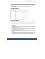
Introduction
Description of Functions
Intelligence heavy-duty Pan/Tilt is an all-in-one high-tech
monitoring product, which integrates high-definition color video
camera, universal gear change pan-tilt and multi-function decoder,
infrared LED, character list folds to add, alarm function. This
product furthest reduces the processes of connection an
installation between system reliability. Also the video camera is
very easy to install and maintain, has many features, such as
perfect shape, legerity and convenience, simple operation and etc.
1. Integrate multi-function decoder
a. Built-in decoder consists of multi-protocol and communications
protocol. Communication serial baud rate (2400~9600) is
adjustable. Using the simple finger-switch inside the device, the
products can be compatible with kinds of systems and has very
high commonality.
b. RS485 serial control, addresses of P/T is from 1~255
2. Integrate full-view rotary station
a. Horizontal 360°unlimited continuous rotation, pa n speed is 100°/s
and Manual control speed can be adjusted from 0.1 ~60°per
second continuously;Vertical rotation range is -75°~85°Tilt speed
is 60°/s and manual control speed can be adjusted f rom 0.1
~40°per second continuously.
b. Low speed's circulating a steady and super and low voice, not film
oscillation
c. The realization is all-directions to keep watch on without the blind
spot, positioning accuracy to reach ± 0. 1
3:
:High intelligence
4
a.
b.
Provides 128 preset points. power-off memory
Provide setting of scanning track and select scanning track
function.
c. Four groups of scanning tracks: Every group of scanning track
can set Max. 16 preset positions.
d.
Limiting speed when Long focal distance. Can be quickly
accurate to search a target
4. Camera function: The actual function makes reference to the
camera module.
a. Focus:Draw near & Push far
b. Zoom :Draw near & Push far
c. Backlight compensation:On & OFF
d. White Balance:When the display picture appears a color to
lose really, the customer can establish various mode through
a setting.
e. Min. illumination set : Under general circumstance the
camera work is in the automatic appearance, when the
illumination is lower than 1Lux, the camera will cut over
automatically Min. illumination can also adjust by manual
way.
f.
5.
Other faction of camera control by menu of system.
Alarm Input & Output
a.
4 Alarm input ,Normal Open, closing for alarm
b.
2 Alarm output,Normal Open, Normal Close Output
c.
When the system identifies the alarm signal, the P/T and
5
camera will work immediately, and report the picture of alarm
district to main monitor.
6. Infrared System
a.
The infrared system is normally under automatic control state.
The infrared lamp shall act followed by open/close of the low
illumination of the camera;
b.
The open/close state of the infrared lamp can be changed by the
menu manually;
c.
The default option on the menu of the infrared lamp is OFF.
Normally
the
system
detects
external
illumination
and
opens/closes the infrared lamp automatically. If the user changes
the option of the infrared lamp into ON, the infrared system is
changed into the manual control; if changing back into the
automatic control, the user should set the option on the menu of
the infrared at OFF.
7. Brush function.
6
3. Specification
Spec.
Faction
of P/T
Power Supply
DC 12V / AC24V
Power consumption
30VA
Weight
6Kg
Installation
top mounted, wall mounted
Relative humidity
10-90%
Work temperature
-35 ~55
Waterproof Class
IP66
Pan speed
100°max
Tilt speed
60°max
Preset position
128 preset potions
Tracks
4 Tracks
Scanning speed
0.5°~30°/s
IR LED
High Brightness LED 36pcs/18pcs
Infrared LED rang 80 meters
IR
LED
power consumes
6W/10W
IR LED CONTROL
Auto/ Manual control on menu
LED life
More than 20000 hours
4 Input
Normal Open, closing for alarm
2 Output
Normal Open, Normal Close Output
Alarm
7
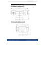
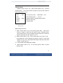
4 Explanation of Product
4.1 Drawing1 (with brush )
4.2 Drawing2(
( without brush)
)
8
4.3 Installation
Plain Base Installation
Steps of installation
1. Remove the bottom plate of the pan/tilt;
2. Set the corresponding information in accordance with the
schematic drawing of the dip-switch of addresses, protocols and
baud rates;
3. Install the bottom plate of the pan/tilt and take care of the tightness
of waterproof seal ring;
4. If vehicle used, first of all fix the Shock Bracket on the bottom of the
pan/tilt then fix the whole pan/tilt;
5. If the plain base is used, fix the pan/tilt onto the fixation hole of the
pan/tilt
6.Connect the output wires of the socket according to relative colors
on the schematic drawing and do not make wrong connections;
9
7. For the common pan/tilt, 10-core socket is used as the alarm
interface and detailed connection can be seen from the
description of colors of terminals.
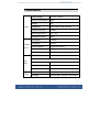
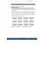
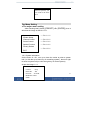
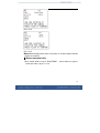
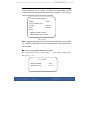
4.3 ID code setting
The ID code setting of P/T set by 8 digital-switch, address of P/T is
from 1~255, about the Stir code of addresses 1~128, please see
the Appendix .
From DIP-8 to DIP-1 equal to an 8 digital binary systems DIP-8 is
the tallest, DIP-1 is lowest. The each "ON" appearance means 1,
the "OFF" appearance means 0.There is the parts of Stir code of
addresses .Setting as below picture
The Stir codes of addresses 129~255 set as binary system
10
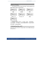
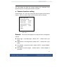
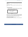
4.4 Protocol Setting
The protocol of P/T set by the No.1, No.2 and No.3 of
BK2 switch, setting as below picture.
Common Baud Rate as below (bps) : B01/9600 ;
ALEC/4800;VCL/4800;PelcoP/4800/9600;PelcoD/2400;
A01/4800;Santachi/9600。
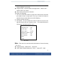
4.5 Setting Baud Rate of P/T
Baud Rate setting of this P/T set by the No.4, No.5 of BK2.Setting as
below pictures.
11
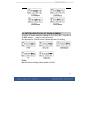
4.6 SETTING PROTOCOL OF ZOOM CAMERA
Protocol of zoom camera setting by the No.6,No.7 and No.8
of BK2 switch ,Setting as below pictures.
Set protocol of YOKO zoom camera as the LG setting.
Note:
Before above setting, Must power off first.
12
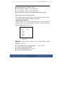
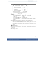
4.7 Explain of connecting :
A.7-Core Input Terminal
B.10-Core Input Terminal
4.71 Description of 7-Core Terminal:
Note:AC 24V power line is at a non-positive and negative
1.DC12V: Red + /AC24V
3.R- (communication-): Yellow
2.DC12V: GND Black-/AC24V
4.Null
5.R+ (communication+):Orange
6.V+: (VF+)
7.V-: (VF-)
4.72 Description of 10-Core Terminal:
:
1.Alarm-1 in: Red
3.Alarm-3 In: Yellow
5.NULL
6.Alarm In COM: Black
8.NULL
9.Alarm NO OUT: Blue
2.Alarm-2 in: Orange
4.Alarm-4 In: Green
7.Alarm Out COM: White
10.Alarm NO OUT: Pink
4.73 Description of 10-Core Socks:
:
The 10-core socket is used for alarm system. If 10-core socket is
not inserted and there is no alarm system;
13
5. OPERATION (Default protocol PELCO-D/2400)
The speed P/T can be controlled remotely horizontal and vertical movement. It is
used with a system controller, separately. It is controlled remotely from the
controller through a serial connection to the RS-485 connector using a
twisted-pair cable.
Conventional Function
1. Pan / Tilt Function
The pan function will move the camera on all horizontal planes, to surveillance
position. The tilt function will move the camera on a vertical plane, to surveillance
position. The speed is variable according to the angle of joystick.
2. Zoom Function
2.1 The filming range can be set using the zoom function.
Press TELE the LCD displays Zoom Tele
Press WIDE the LCD displays Zoom Wide
Note: The bigger zoom is,the slower of joystick ‘s speed is .
2.2 Iris Function
Normally,Focus is AUTO。
Focus level can be adjusted by pressing [NEAR] and [FAR]
Move the joystick, focus will be auto.
3. Preset Memory
The preset memory function will memories camera positions and zoom, focus, etc.
Setting up to 128 preset camera positions can be memorized. Later, you can
14
easily recall any of the preset camera positions by entering its corresponding
number, and the camera will move the memorized position with all the preset
settings.
3.1 To set a preset position
SET + N + ENTER
N: the number of preset position: 1~128
3.2 To call a preset position
When camera positions have been set, you can enter a memorized camera
position number.
Preset + N + ENTER
N: the number of preset position: 1~128
4. Delete a preset position
[PRESET]+ [N] + [OFF]
N: the number of preset position: 1~128
5. To call cruise tracks:
[PRESET]+32+[ENTER]
This command can call the No.1cruise tracks. It can scan preset points no.1 ~ 16.
[PRESET]+53+ [ENTER]
This command can call the No.2cruise tracks. It can scan preset points no.17 ~
31.
[PRESET]+49+ [ENTER]
This command can call the No.3cruise tracks. It can scan preset points no.33 ~
48.
[PRESET]+50+ [ENTER]
This command can call the No.1cruise tracks. It can scan preset points no.65 ~
80.
Note: If some points are not been set or delete, it will not scanning these points
15
when cruising. Resort 3 seconds in every preset point.
6.Setting scanning track
Method 1:
1. Setting begin scanning track point
[SET] + [51] + [ENTER]
Adjust the position of Speed P/T which you need.
2.Setting finish scanning track point:
[SET] + [52] + [ENTER]
Adjust the position of Speed P/T which you need.
3. Calling scanning:
[PRESET]+51+ [ENTER]
Note: Setting begins and finishes scanning track point first.
4. Stop scanning
[PRESET]+52+ [ENTER]
(Move Joystick also can stop scanning)
When Speed P/T scanning, default state following
a. Speed P/T scan between two points.
b. Scan “begin-point” and “end-point” and resort 3 seconds
c. If “begin-point” and “end-point” superpose, Speed P/T horizontal 360°rotation.
Method 2:
Call scanning
[AUTO]+ [ON]
The Speed P/T scanning 360 degree. Need not to set the preset
point
7. Brush function
16
1.
Open the brush: [PRESET]+ 9 + [ENTER]
2.
Close the brush [SET]+ 9 + [ENTER]
Note: Above operation use for our company’s suited keyboard by
example, detail operation do as your keyboard menu
The definition of key
(N)
54
55
Control object
Power supply
Backlight
compensation
PRESET+N+ENTER
SET+N+ENTER
Come back Initial value
/
ON
OFF
56
Min. illumination
ON
OFF
57
Menu/ Screen Display
ON
OFF
58
Digital Zoom
ON
OFF
59
60
Focus
IRIS
AUTO
AUTO
MANUAL
MANUAL
61
White Balance
AUTO
MANUAL
62
Static image
Image congeal
Normal image
63
Mirror image
Image mirror
Normal image
64
Color/black & white
Color
B/W
17
Operation of camera
Note:
: Some cameras don’t support the above function of them.
Power-off memory
Provide setting of scanning track and select scanning track function. Self-test can
allow to store track that user edits arbitrarily and information power-off memory.
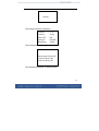
6. Index Diagram of the Screen Menu
18
Index Diagram of the Screen Menu
This is the camera’s OSD function, which include the menu while
opening and the menu while operating.
Open it, and see the start of image, the order of showing is:
Waiting for image
19
Waiting…
The image of system information
Version
: 1.35
Camera
: Sony
Dome ID : 001
Protocol
: PelcoD
Band Rate : 2400
The information of checking itself
Horizontal Check OK
Vertical Check OK
Camera Check OK
The finished information of checking itself
20
Self test passed, you
can control the PTZ
now
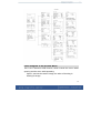
The Menu Setting
● The major menu setting
After checking itself, please {[PRESET] +8+ [ENTER]}, then it
will show the image as the No.1-0-1:
System Info
System Setup
Camera Control
Preset Control
Special Function
Factory Default
→(Pic.1-1-1)
→(Pic.1-2-1)
→(Pic.1-3-1)
→(Pic.1-4-1)
→(Pic.1-5-1)
EXIT
1-0-1 System information
On the menu of 1-0-1, turn up or down the rocker to point to system
info ( or click the up or down key of controlling system) , then turn right
to enter to system info( or click the right key of control system)
As per the image 1-1-1:
Version
: 1.35
Camera
: Sony
Dome ID
: 001
Protocol : PelcoD
Baud Rate: 2400
EXIT
21
Pic.1-1-1
The last pages all show the system setting; the consumer can’t
operate any item of setting the function of system.
●
Camera function setting
On the image 1-0-1, turn up or down the rocker to point to the camera
control,then turn right to enter to the function menu of camera.
Back Light: OFF
Digital Zoom: OFF
Focus Mode : AUTO
IRIS Adjust : AUTO
White Balance: AUTO
Image Freeze : OFF
Next
EXIT
Pic.1-2-1
Remark:The menu of this page is to set the function of integration
camera.
◆ Black Light:to set back light,default “OFF”,choose “ON” if you
need.
◆ Digital Zoom:to set digit zoom, default ”OFF”,choose “ON” if you
need;
◆ Focus Mode:to set focus mode,default “AUTO”,choose “MANU”
if you need;
◆ IRIS Adjust: to set iris adjust ,default “AUTO”,choose “MANU” if
you need;
22
◆ White Balance:to set the model of white balance , show “AUTO”,
choose “MANU” if you need;
◆ Image Freeze: to set the switch of image freeze,default “OFF”,
choose “ON” if you need;
◆ Next: enter to next menu of function
The step is as following:
1) Turn up or down the rocker to point to the choice item, and then
turn right to enter to input area. Turn up or down the rocker to
amend the input value while the on/off is flashing;
2) Set the rest item as step 1;
3) All finished , turn up or down the rocker to point to exit, then turn
right the rocker and exit if it point to next ,turn right and enter to
next image, it will show as Pic.1-2-2:
Image Reverse : OFF
Color Video
: ON
AGC Adjust
: AUTO
Brightness Adjust: AUTO
Zoom Speed
: Fast
Focus Speed
: Fast
Reset
EXIT
Pic.1-2-2
Note:This menu is to set the remind information of screen showing
(Pic.1-2-2)
◆ Image Reverse:Default OFF,select ON;
◆ Color Video: Default setting ON(Color)
,select OFF(BW).
23
◆
◆
◆
◆
◆
AGC Adjust:Default AUTO
Brightness Adjust:Default AUTO;
Zoom Speed:Default Fast, select Slow
Focus Speed: Default Fast, select Slow
Reset: Select this setting , Come back initial producer setting
Steps of setting same as above setting:
Note:Maybe some cameras have no full functions of above menu.
Please according to actual factions set camera.
● Setting Preset Position
The menu of Pic.1-0-1,move rocker down or up to let cursor points
“Preset Control”, then move rocker on right to come into menu of
setting preset position(Pic.1-3-1):
NO. :
Setting
Call
Delete
EXIT
001
Pic.1-3-1
Explain : Above
menu is used to set, call and delete preset
positions.(Pic.1-3-1):
◆ NO.: Display the No. of preset position. (No.:1-128);
◆ Setting: Setting preset position
◆ Call: Call preset position(Pic.1-3-2)
◆ Delete: Delete preset position
24
Setting steps as follow:
1) In menu of Pic.1-3-1,move rocker down or up to let cursor points
“NO.” , then move rocker on right to come into the area of input.
Character blink, move rocker down or up to change the data and
move rocker on right to save and exit. No. range is 1 to 128.
2) Move rocker down or up to let cursor points “setting”, then move
rocker on right to come into the area of setting. The screen
displays the state of setting (Pic.1-3-2).Control the dome camera
by keyboard. After setting, press “close” to save. The screen will
display Pic.1-3-1, cursor points “setting”, Setting is finish. You can
call
this
position
to
confirm
it
is
saved.
NO:
001
Setting
Call
Delete
EXIT
PRESS CLOSE TO SAVE
PRESS OPEN TO ESC
Pic.1-3-2
3)Select the No. of preset position before Call preset position,move
rocker down or up to let cursor points “call”, then move rocker on
right to confirm, the camera will adjust to the preset position(Note: If
the No. Of preset position haven’t been set. Call this No., the camera
will not adjust.)
4)
) After all setting,move rocker down or up to let cursor points
“EXIT”, then move rocker on right to exit setting menu
25
●. Special Function
5)
) In menu of Pic.1-0-1,move rocker down or up to let cursor points
“Special Function”, then move rocker on right to come into the
menu of special function (Pic.1-4-1).
Auto Running
Privacy Zone
Motion Detection
Brush
: OFF
Day/night
: OFF
Auto Back
Auto Learn
Cover offset
Degree Display: OFF
EXIT
Pic.1-4-1
Note:
:Brush(Function of rain strip):If system have this function,
Default display “OFF”;If not have it, default display “NONE”
and will not be change. Press【Preset+9+Enter】 to set brush
function, and press 【SET+9+Enter】 to exit brush function.
Day/night: IR led setting. Default OFF, select ON
Auto Back
: Return automatically(Pic.1-4-1-4)
Auto Learn
:Study function(Pic.1-4-1-5)
Cover offset :
(Pic.1-4-1-8)
Explain:
:The menu of
Pic.1-4-1 is setting function. Move rocker
down or up to select function, and then move rocker on right to come
in the area of input. Character blink, move rocker down or up to
26
change the data and move rocker on right to save and exit.
Step of operation
Move rocker to “Auto Running”, Move rocker on right to enter the
menu of Auto Running as the Pic.1-4-1-1
AUTORUN CONTROL MENU
Set :
BEGIN
Set :
END
Run:
SCAN
Seqno:
1
Run:
SEQ
EXIT
Pic.1-4-1-1
Explain:
::
Set:setting the begin point and the end point of the track
The First Run:scanning
Seqno:setting the scanning speed
The second Run:call scanning
Step of operation:
(1)Move rocker to “Set”, Move rocker on right ,the system will show
as the pic.1-4-1-2,then set the begin point and the end point of track.
27
AUTORUN CONTROL MENU
Set :
BEGIN
Set :
END
Run :
SCAN
Seqno:
1
Run :
SEQ
EXIT
Press close to save
Press open to esc
Pic.1-4-1-2
(2)Move rocker to the first “Run”, Move rocker on right ,the system
will show as the pic.1-4-1-3. press “CLOSE” to scan horizontal 360°;
press “OPEN” to exit.
AUTORUN CONTROL MENU
Set :
BEGIN
Set :
END
Run:
SCAN
Seqno:
1
Run:
SEQ
EXIT
PRESS CLOSE TO RUN
PRESS OPEN TO CANCEL
Pic.1-4-1-3
(3)Move rocker to “Seqno”, Move rocker on right to choose the
speed between 1 to 4.
28
(4)The second Run (SEQ):call track
●.Privacy Zone
Select in menu of Pic.1-4-1,Move rocker down or up to select
“Privacy Zone”, then move rocker on right to come into the menu of
privacy zone (Pic.1-4-11).
NO :
001
Set
Active : show
Save
EXIT
No. of privacy zone, (Select NO.: 1-12).
Enter setting menu.→(1-4-12)
Select to open or close privacy function.
Save privacy zone.
Exit this menu.
Pic.1-4-11
Setting steps as follow:
1) Move rocker down or up to let cursor points “NO.” , then move
rocker on right to come into the area of input. Character blink,
move rocker down or up to change the data, and move rocker on
right to save and exit. No. range is 1 to 12.
2) Move rocker down or up to let cursor points “set” (Pic1-4-12),
then adjust the cover positions and press “Close” to save and
exit(Pic1-4-13), next step adjust the range of privacy and press
“Close” to save and exit.
3) If “Active ON” can setting above steps.;
4) Move rocker down or up to let cursor points “Save” to save
privacy zone.
29
Pic.1-4-12
Pic.1-4-13
Note:
:After setting privacy zone ,must save it. If not the dome camera
will be not memory.
◆. Return automatically
Move rocker down or up to “Auto Back”,move rocker on right to
come into menu, as pic.1-4-1-4
30
AUTO BACK
MENU
AUTO BACK MODE
TIME SET
AUTO BACK BEGIN
AUTO BACK SET
: OFF
: 1MIN
: SET
: BEGIN
Pic.1-4-1-4
Explain:
AUTO BACK MODE: Default OFF ,select ON
TIME SET
: 0-9MIN
AUTO BACK BEGIN :Set begin point
AUTO BACK SET : SEQ1、SEQ2、SEQ3、SEQ4、SCAN、
PRE1
Note: SEQ is track;SCAN is scanning;PRE is preset point.
When “AUTOBACK MODE” set “ON”, during this time, if the
speed dome camera doesn’t do any actions, it will return to set
mode.
◆.Study function
Move rocker down or up to “ Auto Learn”,move rocker on right to
come into
Menu as pic.1-4-1-5
31
AUTO LEARN MENU
TIME
: 00SEC
AUTO LEARN NO: 1
LEARN
BEGIN
RUN
LEARN
EXIT
P1-4-1-5
TIME :Max. 60s. (4 tracks, 60s/track)
AUTO LEARN NO:From1 to 4
Operation:
:
1.Move rocker down or up to “LEARN BEGIN”,move rocker on right
to come into as pic.1-4-1-6
AUTO LEARN MENU
TIME
: 00SEC
AUTO LEARN NO: 1
LEARN
BEGIN
RUN
LEARN
EXIT
PRESS CLOSE TO RUN
PRESS OPEN TO CANCEL
Pic.1-4-1-6
Explain:
:Press “CLOSE” ,screen will show “WAITTING” . “WAITTING”
disappear after a few seconds, the interface automatically
self-learning. Time is Max. 60s. Then the system will show
“LEARN FINISHED”;press “OPEN” to cancel.
32
2.
.Move rocker down or up to “RUN LEARN”,move rocker on right
come into as pic.1-4-1-7,select “CLOSE” to run self-learning, Time
is Max.60s.Then the system will show “Run finished”. If don’t move
rocker, Dome device will circularly self-learn.
AUTO LEARN MENU
TIME
: 00SEC
AUTO LEARN NO: 1
LEARN
BEGIN
RUN
LEARN
EXIT
PRESS CLOSE TO RUN
PRESS OPEN TO CANCEL
Pic.1-4-1-7
Note:
:When the dome device is in the process of learning, press SET
+8 + ENTER, dome device will exit the OSD menu and re-learn from
zero second.
◆Focus on correcting the functional coverage
Move rocker down or up to “Cover offset”, move rocker on right come
into as pic.1-4-1-8
Cover offset
OFFSET MODE
OFFSET LEVEL
: OFF
: 01 LV
33
Pic.1-4-1-8
Explain:
:
OFFSET MODE :Focus on correcting the functional coverage model.
Default OFF ,select ON
OFFSET LEVEL :Focus-level settings. You can choose between 01 and
09.
5. Recovery Function
In menu of Pic.1-0-1,Move rocker down or up to let cursor
points “Factory Default”, then move rocker on right to come into
the menu of recovery function (Pic.1-5-1).
FACTORY
NO
DEFAULT?
YES
Pic.1-5-1
Explain:Pic.1-5-1,There is a reminder that is recovery factory setting
or not. Default setting is NO. If recovery factory setting, you can Move
rocker down or up to choose “YES”, then move rocker on right to
confirm it. After 5 seconds, automatically return main menu.
◆ Exit then Screen Menu
After setting, press [SET+8+ENTER] to exit the screen menu
34
8. General Failure Analysis Table
Problem
Description
Possible Reason
After power on, no
motion and no image
Troubleshooting
Power supply module is damaged
or power is not enough.
Change
Power
cable
improperly
Correct
is
connected
Failure occurs on engineering
line.
Self
test
is
exceptional, there is
image but with motor
noise “wu”
Self-test is normal,
but have no image
Self-check ok
cannot control
but
Eliminate
Mechanical failure
Examine and Repair
Video camera is slantwise
Put right
Power supply not enough
Video
line
mistakenly.
is
connected
Change power that meets
requirements.
It
is
recommended to place the
power switch near the
Speed P/T.
Correct
Video line is poor contact.
Eliminate
Video camera is damaged.
Change
Control
signal
line
is
connected mistakenly.
Correct
Position of Speed P/T does not
match.
Protocol setting is wrong
Reselect
Reset and on power
again
Video line is poor contact.
Eliminate
Power supply not enough
Change
Vague image
P/T
is
controllable.
not
Too much load or communication
distance is too long.
Confirm
resistance
distributor
Add
terminal
code
35
Self-test is exceptional
On power again
Bad connection of control
Press to full connect
Operation of Host has problem.
On power again
Note: Much load or communication distance too far, Connect 120Ω
resistor of the farthest dome pan/tilt from the controller and disconnect
all other resistors; Add coding divider
Packing Accessories as following:
1.
An instruction book
2.
Hexagon screw 4pcs
3.
Flat lock washer 4pcs
4.
Spring lock washer 8pcs
5.
Waterproof screw 4pcs
6.
Waterproof rubber cushion 1 piece
7.
A small cross screwdriver
8.
9.
A pair of gloves
Wall bracket hole bitmap 1 piece
10. Desktop mounting holes bitmap 1 piece.
36
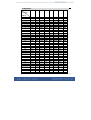
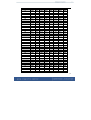
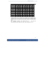
9. Appendix
DIP1
DIP2
DIP3
DIP4
DIP5
DIP6
DIP7
DIP8
ON
OFF
ON
OFF
ON
OFF
ON
OFF
ON
OFF
ON
OFF
ON
OFF
ON
OFF
ON
OFF
ON
OFF
ON
OFF
ON
OFF
ON
OFF
ON
OFF
ON
OFF
ON
OFF
ON
OFF
ON
OFF
ON
ON
OFF
OFF
ON
ON
OFF
OFF
ON
ON
OFF
OFF
ON
ON
OFF
OFF
ON
ON
OFF
OFF
ON
ON
OFF
OFF
ON
ON
OFF
OFF
ON
ON
OFF
OFF
ON
ON
OFF
OFF
OFF
ON
ON
ON
ON
OFF
OFF
OFF
OFF
ON
ON
ON
ON
OFF
OFF
OFF
OFF
ON
ON
ON
ON
OFF
OFF
OFF
OFF
ON
ON
ON
ON
OFF
OFF
OFF
OFF
OFF
OFF
OFF
OFF
OFF
OFF
OFF
ON
ON
ON
ON
ON
ON
ON
ON
OFF
OFF
OFF
OFF
OFF
OFF
OFF
OFF
ON
ON
ON
ON
ON
ON
ON
ON
OFF
OFF
OFF
OFF
OFF
OFF
OFF
OFF
OFF
OFF
OFF
OFF
OFF
OFF
OFF
OFF
OFF
OFF
OFF
ON
ON
ON
ON
ON
ON
ON
ON
ON
ON
ON
ON
ON
ON
ON
ON
OFF
OFF
OFF
OFF
OFF
OFF
OFF
OFF
OFF
OFF
OFF
OFF
OFF
OFF
OFF
OFF
OFF
OFF
OFF
OFF
OFF
OFF
OFF
OFF
OFF
OFF
OFF
OFF
OFF
OFF
OFF
OFF
OFF
OFF
OFF
ON
ON
ON
ON
OFF
OFF
OFF
OFF
OFF
OFF
OFF
OFF
OFF
OFF
OFF
OFF
OFF
OFF
OFF
OFF
OFF
OFF
OFF
OFF
OFF
OFF
OFF
OFF
OFF
OFF
OFF
OFF
OFF
OFF
OFF
OFF
OFF
OFF
OFF
OFF
OFF
OFF
OFF
OFF
OFF
OFF
OFF
OFF
OFF
OFF
OFF
OFF
OFF
OFF
OFF
OFF
OFF
OFF
OFF
OFF
OFF
OFF
OFF
OFF
OFF
OFF
OFF
OFF
OFF
OFF
OFF
OFF
OFF
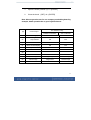
OFF
Dip-switch
Address
1
2
3
4
5
6
7
8
9
10
11
12
13
14
15
16
17
18
19
20
21
22
23
24
25
26
27
28
29
30
31
32
33
34
35
37
36
37
38
39
40
41
42
43
44
45
46
47
48
49
50
51
52
53
54
55
56
57
58
59
60
61
62
63
64
65
66
67
68
69
70
71
72
73
74
75
OFF
ON
OFF
ON
OFF
ON
OFF
ON
OFF
ON
OFF
ON
OFF
ON
OFF
ON
OFF
ON
OFF
ON
OFF
ON
OFF
ON
OFF
ON
OFF
ON
OFF
ON
OFF
ON
OFF
ON
OFF
ON
OFF
ON
OFF
ON
OFF
OFF
ON
ON
OFF
OFF
ON
ON
OFF
OFF
ON
ON
OFF
OFF
ON
ON
OFF
OFF
ON
ON
OFF
OFF
ON
ON
OFF
OFF
ON
ON
OFF
OFF
ON
ON
OFF
OFF
ON
ON
OFF
OFF
ON
ON
ON
ON
ON
ON
OFF
OFF
OFF
OFF
ON
ON
ON
ON
OFF
OFF
OFF
OFF
ON
ON
ON
ON
OFF
OFF
OFF
OFF
ON
ON
ON
ON
OFF
OFF
OFF
OFF
ON
ON
ON
ON
OFF
OFF
OFF
OFF
OFF
OFF
OFF
OFF
ON
ON
ON
ON
ON
ON
ON
ON
OFF
OFF
OFF
OFF
OFF
OFF
OFF
OFF
ON
ON
ON
ON
ON
ON
ON
ON
OFF
OFF
OFF
OFF
OFF
OFF
OFF
OFF
ON
ON
ON
ON
OFF
OFF
OFF
OFF
OFF
OFF
OFF
OFF
OFF
OFF
OFF
OFF
ON
ON
ON
ON
ON
ON
ON
ON
ON
ON
ON
ON
ON
ON
ON
ON
OFF
OFF
OFF
OFF
OFF
OFF
OFF
OFF
OFF
OFF
OFF
OFF
ON
ON
ON
ON
ON
ON
ON
ON
ON
ON
ON
ON
ON
ON
ON
ON
ON
ON
ON
ON
ON
ON
ON
ON
ON
ON
ON
ON
OFF
OFF
OFF
OFF
OFF
OFF
OFF
OFF
OFF
OFF
OFF
OFF
OFF
OFF
OFF
OFF
OFF
OFF
OFF
OFF
OFF
OFF
OFF
OFF
OFF
OFF
OFF
OFF
OFF
OFF
OFF
OFF
OFF
OFF
OFF
OFF
OFF
OFF
OFF
OFF
ON
ON
ON
ON
ON
ON
ON
ON
ON
ON
ON
ON
OFF
OFF
OFF
OFF
OFF
OFF
OFF
OFF
OFF
OFF
OFF
OFF
OFF
OFF
OFF
OFF
OFF
OFF
OFF
OFF
OFF
OFF
OFF
OFF
OFF
OFF
OFF
OFF
OFF
OFF
OFF
OFF
OFF
OFF
OFF
OFF
OFF
OFF
OFF
OFF
38
76
77
78
79
80
81
82
83
84
85
86
87
88
89
90
91
92
93
94
95
96
97
98
99
100
101
102
103
104
105
106
107
108
109
110
111
112
113
114
115
OFF
ON
OFF
ON
OFF
ON
OFF
ON
OFF
ON
OFF
ON
OFF
ON
OFF
ON
OFF
ON
OFF
ON
OFF
ON
OFF
ON
OFF
ON
OFF
ON
OFF
ON
OFF
ON
OFF
ON
OFF
ON
OFF
ON
OFF
ON
OFF
OFF
ON
ON
OFF
OFF
ON
ON
OFF
OFF
ON
ON
OFF
OFF
ON
ON
OFF
OFF
ON
ON
OFF
OFF
ON
ON
OFF
OFF
ON
ON
OFF
OFF
ON
ON
OFF
OFF
ON
ON
OFF
OFF
ON
ON
ON
ON
ON
ON
OFF
OFF
OFF
OFF
ON
ON
ON
ON
OFF
OFF
OFF
OFF
ON
ON
ON
ON
OFF
OFF
OFF
OFF
ON
ON
ON
ON
OFF
OFF
OFF
OFF
ON
ON
ON
ON
OFF
OFF
OFF
OFF
ON
ON
ON
ON
OFF
OFF
OFF
OFF
OFF
OFF
OFF
OFF
ON
ON
ON
ON
ON
ON
ON
ON
OFF
OFF
OFF
OFF
OFF
OFF
OFF
OFF
ON
ON
ON
ON
ON
ON
ON
ON
OFF
OFF
OFF
OFF
OFF
OFF
OFF
OFF
ON
ON
ON
ON
ON
ON
ON
ON
ON
ON
ON
ON
ON
ON
ON
ON
OFF
OFF
OFF
OFF
OFF
OFF
OFF
OFF
OFF
OFF
OFF
OFF
OFF
OFF
OFF
OFF
ON
ON
ON
ON
OFF
OFF
OFF
OFF
OFF
OFF
OFF
OFF
OFF
OFF
OFF
OFF
OFF
OFF
OFF
OFF
OFF
OFF
OFF
OFF
ON
ON
ON
ON
ON
ON
ON
ON
ON
ON
ON
ON
ON
ON
ON
ON
ON
ON
ON
ON
ON
ON
ON
ON
ON
ON
ON
ON
ON
ON
ON
ON
ON
ON
ON
ON
ON
ON
ON
ON
ON
ON
ON
ON
ON
ON
ON
ON
ON
ON
ON
ON
ON
ON
ON
ON
ON
ON
ON
ON
OFF
OFF
OFF
OFF
OFF
OFF
OFF
OFF
OFF
OFF
OFF
OFF
OFF
OFF
OFF
OFF
OFF
OFF
OFF
OFF
OFF
OFF
OFF
OFF
OFF
OFF
OFF
OFF
OFF
OFF
OFF
OFF
OFF
OFF
OFF
OFF
OFF
OFF
OFF
OFF
39
116
117
118
119
120
121
122
123
124
125
126
127
128
…
255
OFF
ON
OFF
ON
OFF
ON
OFF
ON
OFF
ON
OFF
ON
OFF
…
ON
OFF
OFF
ON
ON
OFF
OFF
ON
ON
OFF
OFF
ON
ON
OFF
ON
ON
ON
ON
OFF
OFF
OFF
OFF
ON
ON
ON
ON
OFF
OFF
OFF
OFF
OFF
ON
ON
ON
ON
ON
ON
ON
ON
OFF
ON
ON
ON
ON
ON
ON
ON
ON
ON
ON
ON
ON
OFF
ON
ON
ON
ON
ON
ON
ON
ON
ON
ON
ON
ON
OFF
ON
ON
ON
ON
ON
ON
ON
ON
ON
ON
ON
ON
OFF
OFF
OFF
OFF
OFF
OFF
OFF
OFF
OFF
OFF
OFF
OFF
OFF
ON
ON
ON
ON
ON
ON
ON
ON
Explain:
:DIP1 means 1, DIP2 means 2, DIP3 means 4, DIP4 means
8, DIP5 means 16, DIP6 means 32, DIP7 means 64, DIP8 means
128;
For example: Address 241=128+64+32+16+1 , So set the
DIP1,DIP5 DIP6, DIP7,DIP8 for “ON”, other switches for “OFF”
40