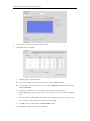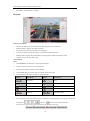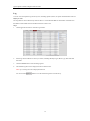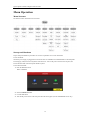
1
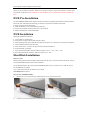
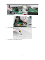
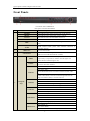
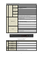
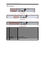
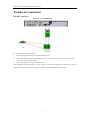
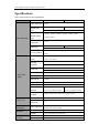
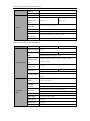
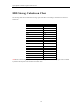
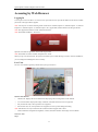
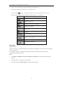
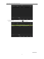
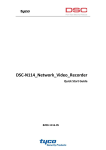
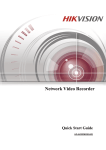
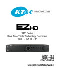
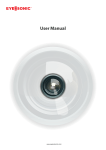
Digital Video Recorder Quick Operation Guide UD.6L0202B0063A01 Quick Operation Guide of Digital Video Recorder Thank you for purchasing our product. If there is any question or request, please do not hesitate to contact dealer. This manual is applicable to DS-7204HFHI-ST, DS-7208HFHI-ST, DS-7204HFHI-SE and DS-7208HFHI-SE DVR. DVR Pre-Installation The DS-7200HFHI-ST&SE DVR is highly advanced surveillance equipment that should be installed carefully. Please take into consideration the following precautionary steps before installation of the DVR. 1. Keep all liquids away from the DVR. 2. Install the DVR in a well-ventilated and dust-free area. 3. Ensure environmental conditions meet factory specifications. 4. Install a manufacturer recommended HDD. DVR Installation During the installation of the DVR: 1. 2. 3. 4. 5. 6. 7. 8. Use brackets for rack mounting. Ensure there is ample room for audio and video cables. When installing cables, ensure that the bend radius of the cables are no less than five times than its diameter. Connect both the alarm and RS-485 cable. Allow at least 2cm (~0.75-inch) of space between racks mounted devices. Ensure the DVR is grounded. Environmental temperature should be within the range of -10 ºC ~ 55 ºC, 14ºF ~ 131ºF. Environmental humidity should be within the range of 10% ~ 90%. Hard Disk Installation Before you start: Before installing a hard disk drive (HDD), please make sure the power is disconnected from the DVR. A factory recommended HDD should be used for this installation. For the HDD installation steps between DS-7200HFHI-ST&SE devices are similar, here we take the steps of DS-7204HFHI-ST as example. Up to 2 SATA hard disks can be installed on your DVR. Tools Required: Screwdriver. Steps (for DS-7200HFHI-ST&SE): 1. Remove the cover from the DVR by unfastening the screws on the back and side. 2. Connect one end of the data cable to the motherboard of DVR and the other end to the HDD. 1 Quick Operation Guide of Digital Video Recorder 3. Connect the power cable to the HDD. 4. Place the HDD on the bottom of the device and then fasten the screws on the bottom to fix the HDD. 5. Re-install the cover of the DVR and fasten screws. 2 Quick Operation Guide of Digital Video Recorder Front Panels Front Panel of DS-7200HFHI-ST Description of Control Panel Buttons No. Name 1 Function Description POWER Power indicator turns yellow once the power switch turns on. READY Ready indicator turns yellow when system is running. STATUS Status indicator turns red when SHIFT mode is on. ALARM Alarm indicator turns red when a sensor alarm is detected. HDD indicator blinks red when data is being read from or written to HDD HDD. TX/RX 2 IR Receiver 3 USB Interface TX/RX indictor blinks yellow when network connection is functioning properly. Receiver for IR remote. Universal Serial Bus (USB) ports for additional devices such as USB mouse and USB Hard Disk Drive (HDD). Switch between the numeric or letter input and functions of the SHIFT composite keys. (Input letter or numbers when the light is out; Realize functions when the light is red.) 1/MENU Enter numeral “1”; Access the main menu interface. Enter numeral “2”; Enter letters “ABC”; 2/ABC/F1 The F1 button when used in a list field will select all items in the list. In PTZ Control mode, it will turn on/off PTZ light and when the image is zoomed in, the key is used to zoom out. Enter numeral “3”; 4 Composite 3/DEF/F2 Keys Enter letters “DEF”; The F2 button is used to change the tab pages. In PTZ control mode, it zooms in the image. Enter numeral “4”; 4/GHI/ESC Enter letters “GHI”; Exit and back to the previous menu. Enter numeral “5”; Enter letters “JKL”; 5/JKL/EDIT Delete characters before cursor; Check the checkbox and select the ON/OFF switch; Start/stop record clipping in playback. Enter numeral “6”; 6/MNO/PLAY Enter letters “MNO”; Playback, for direct access to all-day playback interface. 3 Quick Operation Guide of Digital Video Recorder Enter numeral “7”; 7/PQRS/REC Enter letters “PQRS”; Open the manual record interface. Enter numeral “8”; Enter letters “TUV”; 8/TUV/PTZ Access PTZ control interface. Enter numeral “9”; 9/WXYZ/PREV Enter letters “WXYZ”; Multi-channel display in live view. Enter numeral “0”; 0/A Shift the input methods in the editing text field. (Upper and lowercase, alphabet, symbols or numeric input). The DIRECTION buttons are used to navigate between different fields and items in menus. In the Playback mode, the Up and Down button is used to speed up and slow down recorded video. The Left and Right button will select DIRECTION the next and previous record files. In Live View mode, these buttons can be used to cycle through channels. In PTZ control mode, it can control the movement of the PTZ 5 camera. The ENTER button is used to confirm selection in any of the menu modes. It can also be used to tick checkbox fields. ENTER In Playback mode, it can be used to play or pause the video. In single-frame Playback mode, pressing the button will advance the video by a single frame. In Auto-switch mode, it can be used to stop /start auto switch. Front Panel of DS-7200HFHI-SE Description of Front Panel No. Name POWER 1 STATUS TX/RX 2 IR Receiver 3 USB Interfaces Function Description Power indicator turns yellow when the power switch on the real panel is turned on. Status indicator blinks red when data is being read from or written to HDD. TX/RX indictor blinks yellow when network connection is functioning properly. Receiver for IR remote Universal Serial Bus (USB) ports for additional devices such as USB mouse and USB Hard Disk Drive (HDD). 4 Quick Operation Guide of Digital Video Recorder Rear Panels DS-7204HFHI-SE DS-7204HFHI-ST DS-7208HFHI-ST&SE No. Item Description 1 VIDEO IN HD-SDI interface for video input. 2 AUDIO IN RCA connector 3 AUDIO OUT RCA connector 4 VGA DB9 connector for VGA output. Display local video output and menu. 5 HDMI HDMI video output connector. 6 USB Port Universal Serial Bus (USB) port for additional devices. 7 Network Interface Connector for network 8 RS-485 Interface Connector for RS-485 devices. 9 Power Supply DC 12V power supply. 10 Power Switch Switch for turning on/off the device. 11 GND Ground 5 Quick Operation Guide of Digital Video Recorder Peripheral Connections RS-485 Connection Rear Panel of DS-7204HFHI-SE To connect RS-485 devices to the DVR: 1. Disconnect pluggable block from the RS-485 terminal block. 2. Press and hold the orange part of the pluggable block; insert signal cables into slots and release the orange part. Ensure signal cables are in tight. 3. Connect pluggable block back into terminal block. Note: The RS-485 unit can be used as T+ and T- when it’s working in the output mode, and R+ and R- when it’s working in the input mode. We take the RS-485 connection of DS-7204HFHI-SE as an example. 6 Quick Operation Guide of Digital Video Recorder Specifications Table 1 Specification for DS-7204HFHI-ST Model DS-7204HFHI-ST Video compression H.264 HD-SDI video 4-ch input HD-SDI interface (800 mVp-p, 75 Ω) Supported HD-SDI camera Video/Audio input DS-7208HFHI-ST types Audio compression 8-ch 1080I60, 1080I50, 1080P30, 1080P25, 720P60, 720P50, 720P30, 720P25 G.711u 4-ch Audio input Two-way audio in 8-ch RCA (2.0 Vp-p, 1 KΩ) 1-ch, RCA (2.0 Vp-p, 1 KΩ), (using the 1st channel of audio input) HDMI / VGA 1920 ×1080 / 60 Hz,1280 ×1024 / 60 Hz, 1280 ×720 / 60 Hz, output 1024 ×768 / 60 Hz Encoding Main stream: 1080P / 720P / VGA / 4CIF / CIF resolution Sub-stream: 4CIF(non-real-time) / CIF / QCIF / QVGA Main stream: 1/16 fps ~ Real time frame rate Frame rate Sub-stream: 1/16 fps ~ Real time frame rate Video/Audio output Video bitrate 32 Kbps-16 Mbps Audio output 1-ch, RCA (Linear, 1KΩ) Audio bitrate 64 Kbps Dual-stream Support Stream type Video, Video & Audio Synchronous 4-ch 8-ch playback (up to 2-ch 1080P real time) (up to 2-ch 1080P real time) Playback resolution Output bandwidth Remote access Remote connection Network management Network protocols 1080P / 720P / VGA / 4CIF / CIF / QVGA / QCIF 128Mbps 128 TCP/IP, PPPoE, DHCP, DNS, DDNS, NTP, SADP, SMTP, SNMP, NFS, iSCSI, UPnP™ SATA 2 SATA interfaces Capacity Up to 4 TB capacity for each disk External Network interface 1; 10M / 100M / 1000M self-adaptive Ethernet interface interfaces Serial interface 1; standard RS-485 serial interface, half-duplex Hard disk 7 Quick Operation Guide of Digital Video Recorder USB port 2 × USB2.0 Alarm in / out 4 / 1 (optional) Power supply 12V DC Consumption (without hard Max. 15 W Max. 20 W disks) Working General temperature -10 ºC ~ +55 ºC (14 ºF ~ 131 ºF) Working humidity 10% ~ 90% Chassis 19-inch rack-mounted 1U chassis Dimensions (W × D × H) Weight 445 × 290 ×45 mm (17.5 ×11.4 × 1.8 inch) 4 kg / 8.8lb (without hard disk) Table 2 Specification for DS-7200HFHI-SE Model DS-7204HFHI-SE Video compression H.264 HD-SDI video 4-ch input HD-SDI interface (800 mVp-p, 75 Ω) Supported HD-SDI camera Video/Audio input types Audio compression 8-ch 1080I60, 1080I50, 1080P30, 1080P25, 720P60, 720P50, 720P30, 720P25 G.711u 4-ch Audio input Two-way audio in Video/Audio DS-7208HFHI-SE 8-ch RCA (2.0 Vp-p, 1 KΩ) 1-ch, RCA (2.0 Vp-p, 1 KΩ), (using the 1st channel of audio input) HDMI / VGA 1920 ×1080 / 60 Hz,1280 ×1024 / 60 Hz, 1280 ×720 / 60 Hz, output 1024 ×768 / 60 Hz Encoding Main stream: 1080P@12fps / 720P / VGA / 4CIF / CIF resolution Sub-stream: 4CIF(non-real-time) / CIF / QCIF / QVGA Main stream: 1/16 fps ~ Real time frame rate Frame rate Sub-stream: 1/16 fps ~ Real time frame rate output Video bitrate 32 Kbps-16 Mbps Audio output 1-ch, RCA (Linear, 1KΩ) Audio bitrate 64 Kbps Dual-stream Support Stream type Video, Video & Audio 8 Quick Operation Guide of Digital Video Recorder Synchronous 4-ch 8-ch playback (up to 2-ch 720P real time) (up to 2-ch 720P real time) Playback resolution Output bandwidth Remote access Remote connection Network management Network protocols 1080P / 720P / VGA / 4CIF / CIF / QVGA / QCIF 128Mbps 128 TCP/IP, PPPoE, DHCP, DNS, DDNS, NTP, SADP, SMTP, SNMP, NFS, iSCSI, UPnP™ SATA 1 SATA interface Capacity Up to 4 TB capacity for each disk Network interface 1; 10M / 100M / 1000M self-adaptive Ethernet interface External Serial interface 1; standard RS-485 serial interface, half-duplex interfaces USB port 2 × USB2.0 Alarm in / out 4 / 1 (optional) Power supply 12V DC Hard disk 2 SATA interfaces Consumption (without hard Max. 15 W Max. 20 W disk) Working temperature General -10 ºC ~+55 ºC (14 ºF ~ 131 ºF) Working humidity 10% ~ 90% Chassis Stand-alone 1U chassis Dimensions 315×230×45 mm 445×290×45mm (W × D × H) (12.3×9.0×1.8 inch) (17.3×11.3×1.8 inch) 2 kg / 4.4lb 4 kg / 8.8lb 19-inch rack-mounted chassis Weight (without hard disks) 9 1U Quick Operation Guide of Digital Video Recorder HDD Storage Calculation Chart The following chart shows an estimation of storage space used based on recording at one channel for an hour at a fixed bit rate. Bit Rate 96K 128K 160K 192K 224K 256K 320K 384K 448K 512K 640K 768K 896K 1024K 1280K 1536K 1792K 2048K 4096K 8192K 16384K Storage Used 42M 56M 70M 84M 98M 112M 140M 168M 196M 225M 281M 337M 393M 450M 562M 675M 787M 900M 1800M 3600M 7200M Note: Please note that supplied values for storage space used are just for reference. Storage space used is estimated by formulas and may have some deviation from actual value. 10 Quick Operation Guide of Digital Video Recorder Accessing by Web Browser Logging In You can get access to the device via web browser. Open web browser, input the IP address of the device and then press Enter. The login interface appears. Note: You may use one of the following listed web browsers: Internet Explorer 6.0, Internet Explorer 7.0, Internet Explorer 8.0, Internet Explorer 9.0, Internet Explorer 10.0, Apple Safari, Mozilla Firefox, and Google Chrome. Note: The supported resolutions include 1024*768 and above. Note: The default IP address is 192.0.0.64. Input the user name and password, and click the Login button. Note: The default user name is admin, and password is 12345. When you log in for the first time, the system will remind you to install the Plug-in control. After the installation, you can configure and manage the device remotely. Live View The live view interface appears by default when you log in the device. Interface Introduction ① Channel List: Displays the list of channels and the playing and recording status of each channel. ② Live View Window: Displays the image of channel, and multi-window division is supported. ③ Play Control Bar: Play control operations are supported. ④ PTZ Control: Pan, tilt, zoom operations are supported, as well as preset editing and calling. Note: PTZ function can only be realized if the connected camera supports PTZ control. ⑤ Video Parameters Configuration: Brightness, contrast, saturation and hue of the image can be modified. Start Live View Steps: 11 Quick Operation Guide of Digital Video Recorder 1. In the live view window, select a playing window by clicking the mouse. 2. Double click a camera from the device list to start the live view. 3. You can click the button on the toolbar to start the live view of all cameras on the device list. Refer to the following table for the description of buttons on the live view window: Icon Description Select the window-division mode Start/Stop all live view / Capture pictures in the live view mode Start/Stop all recording / Previous page Next page / / Open/Close audio Start/Stop two-way Audio Adjust volume / Enable/Disable digital zoom Recording Before you start Make sure the device is connected with HDD or network disk, and the HDD or network disk has been initialized for the first time to use. Two recording types can be configured: Manual and Scheduled. The following section introduces the configuration of scheduled recording. Steps: 1. Click Remote Configuration> Camera Settings> Record Schedule to enter Record Schedule settings interface. 2. Select the camera to configure the record schedule. 3. Check the checkbox of Enable Schedule to enable recording schedule. 12 Quick Operation Guide of Digital Video Recorder 4. Choose the day in a week to configure scheduled recording. 5. Click Edit to edit record schedule. 1) Configure All Day or Segment Record: If you want to configure the all-day recording, please check the All Day checkbox. If you want to record in different time sections, check the Segment Record checkbox. Set the Start Time and End Time. Note: The time of each segment can’t be overlapped. Up to 8 segments can be configured. 2) Select a Record Type. The record type can be Normal, Motion, Alarm, Motion & Alarm, and Motion | Alarm. 3) Check the checkbox of Select All and click Copy to copy settings of this day to the whole week. You can also check any of the checkboxes before the date and click Copy. 4) 6. Click OK to save the settings and exit the Edit Schedule interface. Click Advanced to configure advanced record parameters. 13 Quick Operation Guide of Digital Video Recorder 7. Click Save to validate the above settings. Playback Interface Introduction ① Channel List: Displays the list of channels and the playing status of each channel. ② Playback Window: Displays the image of channel. ③ Play Control Bar: Play control operations are supported. ④ Time Line: Displays the time bar and the records marked with different colors. ⑤ Playback Status: Displays the playback status, including channel number and playback speed. ⑥ Calendar: You can select the date to play. Start Playback Steps: 1. Click Playback on the menu bar to enter playback interface. 2. Click the camera from the device list for playback. 3. Select the date from the calendar and click Search. 4. Click the Play button to play the video file searched on the current date. 5. Use the buttons on the toolbar to operate in playback mode. Button / / 6. Description Button Description Play/Pause Stop Slow down Speed up Play by single frame Capture Stop all playback Download Video clip / Open/Close audio You can drag the progress bar with the mouse to locate the exact playback point. You can also input the time in the textbox and click button to locate the playback point. The color of the video on the progress bar stands for the different video types. 14 Quick Operation Guide of Digital Video Recorder Log You can view and export the log files at any time, including operation, alarm, exception and information of device. Before you start The Log function can be realized only when the device is connected with HDD or network disk. And make sure the HDD or network disk has been initialized for the first time to use. Steps: 1. Click Log on the menu bar to enter the Log interface. 2. Set the log search conditions to refine your search, including the Major Type, Minor Type, Start Time and End Time. 3. Click the Search button to start searching log files. 4. The matched log files will be displayed on the list shown below. Note: Up to 100 log files can be displayed each time. You can click the button to save the searched log files to local directory. 15 Quick Operation Guide of Digital Video Recorder Menu Operation Menu Structure The menu structure of the DVR is shown below: Startup and Shutdown Proper startup and shutdown procedures are crucial to expand the service time of the DVR. To start the DVR: Check the power supply is plugged into an electrical outlet. It is HIGHLY recommended that an Uninterruptible Power Supply (UPS) be used in conjunction with the device. Turn on the power switch on the rear panel; the Power indicator LED on the front panel should be yellow. To shut down the DVR: 1. Enter the Shutdown menu. Menu > Shutdown 2. Select the Shutdown button. 3. Click the Yes button. 4. Turn off the power switch on the rear panel when the note appears (for DS-7200HFHI-SE series only). 16 Quick Operation Guide of Digital Video Recorder After the device starting up, the wizard will guide you through the initial settings, including modifying password, date and time settings, network settings, HDD initializing, and recording. Live View Some icons are provided on screen in Live View mode to indicate different camera status. These icons include: Live View Icons In the live view mode, there are icons at the right top of the screen for each channel, showing the status of the record and alarm in the channel, so that you can find problems as soon as possible. Indicating that there is an alarm or are alarms. Alarm includes (video loss, tampering, motion detection or sensor alarm, etc.). Recording (manual record, schedule record, motion detection or alarm triggered record) Alarm & Recording Record Settings Before you start: Make sure that the HDD has already been installed. If not, please install a HDD and initialize it. You may refer to the user manual for detailed information. Purpose: Two kinds of record types are introduced in the following section, including Instant Record and All-day Record. And for other record types, you may refer to the user manual for detailed information. Note: After rebooting all the manual records enabled are canceled. Instant Record • Option 1: On the live view window of each channel, there is a quick setting toolbar which shows on the bottom of the window when you click on it. Click the icon to enable the record, and the icon turns to record, then the icon turns to . 17 . And click icon to disable the Quick Operation Guide of Digital Video Recorder • Option 2: Steps: 1. Enter the Manual settings interface. Menu> Manual 2. Enable manual record. Click the status icon Or click the status icon 3. before camera number to change it to . of Analog to enable manual record of all channels. Disable manual record. Click the status icon Or click the status icon to change it to . of Analog to disable manual record of all channels. All-day Record Perform the following steps to set the all-day recording. • Option 1: On the live view window, right lick the window and move the cursor to the Start Recording option, and select Normal Record or Motion Detection Record on your demand. And click the Yes button in the popup Attention message box to confirm the settings. Then all the channels will start to record in the selected mode. • Option 2: Steps: 1. Enter the Manual settings interface. Menu> Manual 2. Click the icon of corresponding record types to set all-day record of that type, Normal and Motion Detection are selectable. 18 Quick Operation Guide of Digital Video Recorder 3. And click the Yes button in the popup Attention message box to confirm the settings. Playback Play back the record files of a specific channel in the live view menu. Instant playback by channel Choose a channel under live view using the mouse and click the button in the shortcut operation menu. Note: Only record files recorded during the last five minutes on this channel will be played back. All-day Playback by channel 1. Enter the All-day Playback menu. Mouse: right click a channel in live view mode and select All-day Playback from the menu. Front Panel: press PLAY button to play back record files of the channel under single-screen live view. Under multi-screen live view, record files of the top left channel (not masked) will be played back. Note: pressing numerical buttons will switch playback to related channels during playback process. 2. Playback management. The toolbar in the bottom part of Playback interface can be used to control playing process. 19 Quick Operation Guide of Digital Video Recorder The channel and time selection menu will display by moving the mouse to the right of the playback interface. Just tick the channel or channels if you want to switch playback to another channel or execute simultaneous playback of multiple channels. Backup Recorded files can be backed up to various devices, such as USB flash drives, USB HDDs or USB DVD writers. To export recorded files: 1. Enter Video Export interface. Choose the channel(s) you want to back up and click the Quick Export button. 2. Enter Export interface, choose backup device and click the Export button to start exporting. 20 Quick Operation Guide of Digital Video Recorder 3. Check backup result. Choose the record file in Export interface and click button to check it. 0202021030315 21 Quick Operation Guide of Digital Video Recorder 22