1
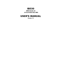
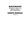
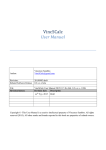
IB510
Socket 7 NS Geode GX1
5.25-inch Embedded Board
USER’S MANUAL
Version 1.0
Acknowledgments
Award is a registered trademark of Award Software International,
Inc.
PS/2 are trademarks of International Business Machines
Corporation.
Microsoft Windows is a registered trademark of Microsoft
Corporation.
Winbond is a registered trademark of Winbond Electronics
Corporation.
All other product names or trademarks are properties of their
respective owners.
ii
IB510 User’s Manual
Table of Contents
Introduction.............................................................. 1
Product Description .......................................................... 1
Checklist .......................................................................... 2
Specifications ................................................................... 3
Board Dimensions............................................................. 5
Installations.............................................................. 6
Installing the CPU ............................................................ 7
Installing the Memory (DIMM)......................................... 8
Setting the Jumpers........................................................... 9
Connectors on IB510 ...................................................... 13
IB510 User’s Manual
iii
This page is intentionally left blank.
iv
IB510 User’s Manual
INTRODUCTION
Introduction
Product Description
The IB510 board is a high-performance multimedia using the 5.25-inch
SBC form factor (Little Board). Based on the NS Geode GX1 and NS
5530A chipset, it features a Socket 7 architecture that supports NS
Geode GX processors with speeds of 200MHz to 333MHz.
National Semiconductor's Geode GX processor is specially designed to
power information and Internet appliances (IA) for entertainment,
education, and business. The Geode GX represents a system-on-chip
solution for IA applications such as thin clients, interactive set-top
boxes, personal Internet access devices, and embedded systems. The
device is available with a typical average power consumption ranging
from 0.8 to 2.5 watts. Operating at lower voltages improves power
consumption and thermal characteristics thus enabling maximum
flexibility in system design.
The IB510 packs all the functions of a versatile system, including VGA,
Audio, Dual Ethernet and LCD panel support. System memory is
provided by one DIMM socket that accommodates up to 256MB
SDRAM.
The IB510 has four RS232 serial communication ports and one PCI
expansion slot. Optionally available is a FT5-CF CompactFlash
daughter card that supports Compact Flash cards and the DXTN510
DSTN daughter card to support DSTN LCD panels and the FT5-TV
daughter card to support TV-OUT.
.
IB510 User’s Manual
1
INTRODUCTION
Checklist
Your IB510 package should include the items listed below. Damaged or
missing items should be reported to your supplier.
• The IB510 5.25-inch SBC
• This User’s Manual
• One floppy diskette containing the following:
• Chipset Patch File
• NS Geode GX VGA Driver
• Realtek RTL8139C Ethernet Drivers
• NS 5530A Audio Drivers
• Optional cables such as:
• 1 Floppy Ribbon Cable
• 1 Audio Cable
• 1 44-pin IDE Ribbon Cable
• 1 COM Port Cable
• 1 Printer Port Cable
• 1 PS/2 Keyboard/Mouse Cable
• 1 VGA Cable
• 1 LAN Cable for two RJ-45 connector with IBLD-B1
• Optional DXTN 510 DSTN daughter card
• Optional FT5-CF CompactFlash daughter card
• Optional FT5-TV TV-OUT daughter card
2
IB510 User’s Manual
INTRODUCTION
Specifications
Support NS Geode GX1, 233MHz~333MHz, 33MHz Bus
Speed
NS Geode 5530A
Award BIOS
Supports ACPI, DMI, PnP
System Memory 1x DIMM socket support up to 256MB capacity
3.3V supported, ECC supported
Multi I/O Chipset Winbond 83977F and 83877TF (keyboard controller is
built-in 83977F)
1x FDD (up to 2.88MB, 3 Mode, LS120)
I/O Features
1x Parallel Port (EPP, ECP Port)
4x Serial Ports (RS232)
1x IrDA TX/RX Headers
2 ports Digital IO Pin Headers
Watch dog function support
Bus Master IDE NS 5530A built-in, Ultra DMA/33 IDE HDD
40-pin headers for primary channel
44-pin headers for secondary channel
NS Geode GX Integrated VGA
On-board VGA
Support CRT & LCD Panels for TFT and DSTN
Optional DXTN510 DSTN daughter card
Optional FT5-TV TV-OUT daughter card
On board LVDS controller
15-pin VGA connector
On-board Audio NS 5530 integrated audio controller
AC97 codec support
Two Realtek RTL8139C Single-Chip Controller
On-board Dual
Ethernet
32-bit performance, PCI bus master capability
Supports 10/100Mbps data transfer rates
Headers for 2 USB ports
USB
One PCI slot
Expansion Slot
Optional through FT5-CF CompactFlash adapter card
CompactFlash
Support
Power Connector (+5V, Gnd, Gnd, +12V) 4-pin connector
Keyboard/Mouse Two 6-pin headers for PS/2 keyboard and PS/2 mouse
Power
GX1 300MHz ( Vcore = 2V) 2A max. (+5V) 250mA max. (+12V)
Consumption
5.25-inch SBC (Little Board)
Form Factor
203mm x 146mm (7.99” x 5.75”)
Dimensions
Processor
Supported
Chipset
BIOS
IB510 User’s Manual
3
INTRODUCTION
4
IB510 User’s Manual
INTRODUCTION
Board Dimensions
IB510 User’s Manual
5
INSTALLATIONS
Installations
This section provides information on how to use the jumpers and
connectors on the IB510 in order to set up a workable system. The topics
covered are:
Installing the CPU.............................................................7
Installing the Memory (DIMM) .........................................8
Setting the Jumpers ...........................................................9
Connectors on IB510....................................................... 13
6
IB510 User’s Manual
INSTALLATIONS
Installing the CPU
The IB510 5.25-inch SBC (Little Board) a Socket 7 processor socket for
NS Geode GX processors.
The Socket 7 processor socket comes with a lever to secure the
processor. Raise this lever to about a 90° angle to allow the insertion of
the processor. Place the processor into the socket by making sure the
notch on the corner of the CPU corresponds with the notch on the inside
of the socket. Once the processor has slid into the socket, return the lever
to the lock position.
After you have installed the processor into the socket, check if the
jumpers for the CPU type and speed are correct.
NOTE: Ensure that the CPU heat sink and the CPU top surface are in
total contact to avoid CPU overheating problem that would
cause your system to hang or be unstable.
IB510 User’s Manual
7
INSTALLATIONS
Installing the Memory (DIMM)
The IB510 5.25-inch SBC supports one 168-pin DIMM socket for a
maximum total memory of 256MB in SDRAM type. The memory
capacities supported are 32MB, 64MB, 128MB and 256MB.
Installing and Removing DIMMs
To install the DIMM, locate the memory slot on the little board and
perform the following steps:
1. Hold the DIMM so that the two keys of the DIMM align with those on
the memory slot.
2. Gently push the DIMM in an upright position until the clips of the slot
close to hold the DIMM in place when the DIMM touches the bottom
of the slot.
3. To remove the DIMM, press the clips with both hands.
Lock
DIMM
Lock
Lock
Top View of DIMM Socket
8
Lock
IB510 User’s Manual
INSTALLATIONS
Setting the Jumpers
Jumpers are used on the IB510 to select various settings and features
according to your needs and applications. Contact your supplier if you
have doubts about the best configuration for your needs. The following
lists the connectors on IB510 and their respective functions.
Jumper Locations on IB510....................................................... 10
SW2(3): CPU Clock Speed Selector .......................................... 11
SW2(4-8): CPU Frequency Selector........................................... 11
JP1: BIOS Voltage Setting ........................................................ 11
JP3: Panel Voltage .................................................................... 12
JP6: Clear CMOS...................................................................... 12
SW1: DSTN Resolution Setting for DXTN510 Card ................. 11
The following conventions are used in this section:
off off on on
Pin 1-2
Short/Closed
↓ ↓ ↑ ↑
IB510 User’s Manual
9
INSTALLATIONS
Jumper Locations on IB510
10
IB510 User’s Manual
INSTALLATIONS
SW2(3): CPU Clock Speed Selector
CPU Clock
SW2(1-3)
CPU Clock
333MHz
SW2(1-3)
300MHz
off on on xx xx xx xx xx
on off on xx xx xx xx xx
233MHz
266MHz
off off off xx xx xx xx xx
on off off xx xx xx xx xx
200MHz
off on off xx xx xx xx xx
SW2(4-8): CPU Frequency Selector
The table below shows the correct setting to match the CPU frequency.
Vcore
1.6V
1.8V
2.0V
2.2V
2.5V
2.9V
SW2(4-8)
4 5 6 7 8
On Off On Off On
Off On Off On On
Off On On On On
Off On Off Off Off
On Off On Off Off
On Off Off On Off
JP1: 5V Voltage Setting
JP1
Setting
Function
Pin 1-2
Short/Closed
No Connect
(Default)
Pin 2-3
Short/Closed
5V
* Warning: The 5V voltage is connected to pin 20 of the primary
IDE channel. Setting JP1 to 2-3 short could damage the hard disk
in the primary IDE channel.
IB510 User’s Manual
11
INSTALLATIONS
JP3: Panel Voltage
JP3
Setting
Function
Pin 1-2
Short/Closed
3.3V (default)
Pin 2-3
Short/Closed
5V
Setting
Function
Pin 1-2
Short/Closed
Clear CMOS
Content
Pin 2-3
Short/Closed
Normal
Operation
JP6: Clear CMOS
JP6
*Note: To clear CMOS contents, remove the jumper from pin 1-2 and
place it on pin 2-3 for about 5 seconds, and then return the jumper to pin
1-2.
JP8: TVCLK for TV-Out
JP8
Setting
Function
Short
TVCLK Not
Available (default)
Open
TVCLK Available
SW1: DSTN Resolution Setting for DXTN510 Card
SW1
640x480 16bit DSTN color
800x600 16bit DSTN color
1024x768 24bit DSTN color
12
1
Off
Off
Off
2
Off
Off
On
IB510 User’s Manual
3
On
Off
Off
4
On
On
On
INSTALLATIONS
Connectors on IB510
The connectors on IB510 allows you to connect external devices such as
keyboard, floppy disk drives, hard disk drives, printers, etc. The
following table lists the connectors on IB510 and their respective
functions.
Connector Locations on IB510 .................................................. 14
J2: Primary and Secondary LAN Connector .............................. 15
J5: VGA CRT Connector .......................................................... 15
J7: Main Power Connector ........................................................ 15
J6, J4: EIDE Connectors ........................................................... 16
J10, J3: LCD Panel Connector................................................... 17
J8: 18-Bit LVDS Connector (DF13-20) ..................................... 18
J11: Parallel Port Connector...................................................... 18
J12: Four COM Ports Connector ............................................... 20
JP4, JP5: Voltage Pins for CF Card Adapter.............................. 20
J14: Audio Connector................................................................ 20
LED1: Power LED .................................................................... 20
J15: Reset Switch 2-pin Header ................................................. 20
J16, J17: IDE LED .................................................................... 20
J18: IrDA Connector ................................................................. 21
J19, J20: PS/2 Keyboard/Mouse Connector................................ 21
J21: Fan Power Connector......................................................... 21
J22: Floppy Drive Connector..................................................... 22
J23: USB Connector.................................................................. 22
IB510 User’s Manual
13
INSTALLATIONS
Connector Locations on IB510
14
IB510 User’s Manual
INSTALLATIONS
J2: Primary and Secondary LAN Connector
Signal Name
Vcc
RX0+
LED02
Vcc
TX0+
Vcc
RX1+
LED11
Vcc
TX1+
Pin #
1
3
5
7
9
11
13
15
17
19
Pin #
2
4
6
8
10
12
14
16
18
20
Signal Name
LED01
RX0GND
GND
TX0LED12
RX1GND
GND
TX1-
J5: VGA CRT Connector
J5 is a 15-pin header for an external VGA CRT female connector.
Signal Name
Red
Green
Blue
N.C.
Ground
Ground
Ground
Ground
Pin
1
3
5
7
9
11
13
15
Pin
2
4
6
8
10
12
14
16
Signal Name
Vcc
N.C.
N.C.
DOCSDA
H-Sync
V-Sync
DOCSCL
N.C.
J7: Main Power Connector
The J7 main power connector has the following pin assignments.
Pin #
1
2
3
4
Signal Name
+5V
Ground
Ground
+12V
IB510 User’s Manual
15
INSTALLATIONS
J6, J4: EIDE Connectors
J6 is the primary IDE connector. J4 is the secondary IDE connector.
J6: IDE1
J4: IDE2
16
Signal Name
Pin #
Pin #
Signal Name
Reset IDE
Host data 7
Host data 6
Host data 5
Host data 4
Host data 3
Host data 2
Host data 1
Host data 0
Ground
DRQ0
Host IOW
Host IOR
IOCHRDY
DACK0
IRQ14
Address 1
Address 0
Chip select 0
Activity
1
3
5
7
9
11
13
15
17
19
21
23
25
27
29
31
33
35
37
39
2
4
6
8
10
12
14
16
18
20
22
24
26
28
30
32
34
36
38
40
Ground
Host data 8
Host data 9
Host data 10
Host data 11
Host data 12
Host data 13
Host data 14
Host data 15
N.C.
Ground
Ground
Ground
Host ALE
Ground
No connect
No connect
Address 2
Chip select 1
Ground
Signal Name
Pin #
Pin #
Signal Name
Reset IDE
Host data 7
Host data 6
Host data 5
Host data 4
Host data 3
Host data 2
Host data 1
Host data 0
Ground
DRQ0
Host IOW
Host IOR
IOCHRDY
DACK1
MIRQ0
Address 1
Address 0
Chip select 0
Activity
Vcc
Ground
1
3
5
7
9
11
13
15
17
19
21
23
25
27
29
31
33
35
37
39
41
43
2
4
6
8
10
12
14
16
18
20
22
24
26
28
30
32
34
36
38
40
42
44
Ground
Host data 8
Host data 9
Host data 10
Host data 11
Host data 12
Host data 13
Host data 14
Host data 15
N.C.
Ground
Ground
Ground
Host ALE
Ground
No connect
No connect
Address 2
Chip select 1
Ground
Vcc
N.C.
IB510 User’s Manual
INSTALLATIONS
J10, J3: LCD Panel Connector
J10 is the pin header for TFT flat panel LCD displays. To support DTSN
displays, the DXTN510 daughter card must be connected to J10 and J3
(10-pin header).
Signal Name Pin # Pin # Signal Name
+12V
1
2
+12V
Ground
3
4
Ground
5V/3.3V
5
6
5V/3.3V
SCL
7
8
Ground
SDA
9
10
TVCLK
B0
11
12
B1
B2
13
14
B3
B4
15
16
B5
CRTHSYNC
17
18
CRTVSYNC
G0
19
20
G1
G2
21
22
G3
G4
23
24
G5
N.C.
25
26
N.C.
R0
27
28
R1
R2
29
30
R3
R4
31
32
R5
Ground
33
34
Ground
FLM(VSYNC)
SHFCLK
35
36
DISPENA(MDE)
LP(HSYNC)
37
38
J10
Ground
39
40
ENABKL
Ground
41
42
N.C.
DNAVDD
43
44
5V/3.3V
J3
Signal Name
3.3V
3.3V
3.3V
Ground
Ground
Ground
Ground
Ground
Pin #
1
2
3
4
5
6
7
8
IB510 User’s Manual
Pin #
9
10
11
12
13
14
15
16
Signal Name
PCIRSTX
DSTNSCS
DSTNSDO
DSTNSDI
DSTNSCLK
Vcc
Vcc
Vcc
17
INSTALLATIONS
J8: 18-Bit LVDS Connector (DF13-20)
Signal Name
TX0Ground
TX15V/3.3V
NC
TX2Ground
TXC5V/3.3V
+12V
Pin #
2
4
6
8
10
12
14
16
18
20
Pin #
1
3
5
7
9
11
13
15
17
19
Signal Name
TX0+
Ground
TX1+
Ground
NC
TX2+
Ground
TXC+
ENABKL
+12V
JP9: Digital I/O Connector
This 10-pin Digital I/O connector supports TTL levels and is used to
control external devices requiring ON/OFF circuitry.
Signal Name
DI0
DI1
No Connect
No Connect
Ground
Pin #
1
2
3
4
5
Pin #
6
7
8
9
10
Signal Name
Vcc
DO0
Ground
DO1
+12V
SPECIFICATIONS:
Digital Input
Input channels: 2 bits
Input Voltage: High: 2.0V (min)
Low: 0.8V (max)
Input Load:
High: 0.05mA max at 2.7V
Low: 0.4mA max at 0.5V
Register Address: 240H
Register Format: BIT:
D1 D0
Value: DI1 DI0
18
IB510 User’s Manual
INSTALLATIONS
Digital Output
Output channels: 2 bits
Output voltage: High: Source -0.4mA at 2.4V min
Low: Sink 8mA at 0.5V max
Register Address: 240H (Write)
Register Format: BIT:
D1
D0
Value: DO1 DO0
J11: Parallel Port Connector
The following table describes the pin out assignments of this connector.
Signal Name
Line printer strobe
PD0, parallel data 0
PD1, parallel data 1
PD2, parallel data 2
PD3, parallel data 3
PD4, parallel data 4
PD5, parallel data 5
PD6, parallel data 6
PD7, parallel data 7
ACK, acknowledge
Busy
Paper empty
Select
Pin #
1
2
3
4
5
6
7
8
9
10
11
12
13
IB510 User’s Manual
Pin #
14
15
16
17
18
19
20
21
22
23
24
25
N/A
Signal Name
AutoFeed
Error
Initialize
Select
Ground
Ground
Ground
Ground
Ground
Ground
Ground
Ground
N/A
19
INSTALLATIONS
J12: Four COM Ports Connector
J12A (COM1), J12B (COM2), J12C (COM3) and J12D (COM4) are the
onboard serial ports on IB510.
Pin #
Signal Name (RS-232)
1
2
3
4
5
6
7
8
9
10
DCD, Data carrier detect
RXD, Receive data
TXD, Transmit data
DTR, Data terminal ready
Ground
DSR, Data set ready
RTS, Request to send
CTS, Clear to send
RI, Ring indicator
No Connect.
JP4, JP5: Voltage Pins for CF Card Adapter
IB-510 offers an optional CF card adapter (for Compact Flash cards)
that connects to the IDE1 connector and JP4/JP5 voltage pins.
J14: Audio Connector
J14, a 12-pin header connector, supports an optional external connector
supporting 3 sockets for Line Out, Line In and Mic functions. The
following table shows the pin assignments of this connector.
Signal Name
Line Out R
Ground
Line In R
Ground
Mic
Ground
Pin #
1
3
5
7
9
11
Pin #
2
4
6
8
10
12
Signal Name
Line Out L
Ground
Line In R
Ground
BIAS
NC
LED1: Power LED
J15: Reset Switch 2-pin Header
J16, J17: IDE LED
20
IB510 User’s Manual
INSTALLATIONS
J18: IrDA Connector
J18 is the IrDA connector used to connect to an IrDA interface that can
be made to communicate with wireless devices (or other computers).
These devices come with instruction on the necessary BIOS settings
(UART Mode) and installation procedure.
Pin # Signal Name
+5V IRRX IRTX
1
+5V
2
No Connect
3
Ir RX
N.C. GND
4
Ground
5
Ir TX
J19, J20: PS/2 Keyboard/Mouse Connector
J19, a 10-pin header connector, has functions for both keyboard and
mouse. J20 is a 6-pin header that supports both keyboard and mouse.
Signal Name Pin # Pin # Signal Name
N.C.
10
5
N.C.
KB clock
9
4
Mouse clock
KB data
8
3
Mouse data
Vcc
7
2
Vcc
Ground
6
1
Ground
Pin #
1
2
3
4
5
6
Signal Name
KB data
MS data
Ground
Vcc
KB clock
MS clock
J21: Fan Power Connector
J21 is a 3-pin header for a CPU fan. The fan must be a 12V fan.
Pin #
1
2
3
Signal Name
N.C.
+12V
Ground
IB510 User’s Manual
21
INSTALLATIONS
J22: Floppy Drive Connector
J22 of the IB510 is a 34-pin header and will support up to 2.88MB
floppy drives.
Signal Name
Ground
Ground
Ground
Ground
Ground
Ground
Ground
Ground
Ground
Ground
Ground
Ground
Ground
Ground
Ground
Ground
Ground
Pin #
1
3
5
7
9
11
13
15
17
19
21
23
25
27
29
31
33
Pin #
2
4
6
8
10
12
14
16
18
20
22
24
26
28
30
32
34
Signal Name
RM/LC
No connect
No connect
Index
Motor enable 0
Drive select 1
Drive select 0
Motor enable 1
Direction
Step
Write data
Write gate
Track 00
Write protect
Read data
Side 1 select
Diskette change
J23: USB Connector
J23 is the onboard USB pin-header that supports an external USB
connector with two ports.
Pin #
1
5
2
6
3
7
4
8
22
Signal Name
Vcc
USBUSB+
Ground
IB510 User’s Manual