1
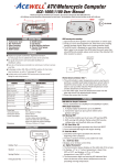
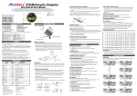
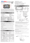
ATV/Motorcycle Computer ACE-1600 User Manual Thanks for bought the ATV/Motorcycle computer, please read the manual before you install the computer. 2 8 3 9 7 4 5 English RESET 1 RESET 1. Tachometer Scale 2. Bar Tachometer 3. 1st row: Current & Max. Speedometer 4. 2nd row: Other func ons 5. RESET Bu on 6. MODE Bu on 7. Bar Thermometer /Fuel Gauge 8. RPM Warning Indicator 9. Temperature /Fuel Gauge Warning LED FEATURES Displays bar-graphic tachometers, speedometer, bar-graphic fuel gauge/temperature meter plus one addi onal func on at the same me. Includes 50 lap mers and a wiring remote control switch . Powered using either the internal CR2032 ba ery or the bike’s ba ery. Bar-graph tachometers with selectable 10,000rpm or 20,000rpm redline. Allows end user to adjust odometer when the odometer is less than 30km / 18.6 miles.. Fuel gauge includes +/-‐ 100, 250 and 510 Ohm op ons for fuel sender input resistance, as well as “fuel gauge off” mode. Includes bracket, RPM sensing wire, speed sensor, thermo sensor , fi ng kits, wiring harness and wiring remote control switch. SPECIFICATIONS Function Simbolo Bar Tachomete Speedometer Trip meter Odometer Digital Tachometer Digital Thermometer 12/24 Hour Clock Average speed Riding Time Hour meter Voltage Gauge Maximum speed Maximum Thermometer Total Hour Meter Bar-Fuel Meter or Bar Temperature Meter LAP timer Specifications 500-10,000 rpm 1,000-20,000rpm options km/H/MPH 100-19,900 rpm, Trip 2.4-399.9 km/h (248.5 MPH) 2.4-399.9 KM/h (248.5 MPH), rpm 2.4-399.9 KM/h (248.5 MPH), C or F +50℃-180℃/ 122℉-356℉ +50℃-180℃ / 122℉-356℉ 0.0-999.9 KM/Miles AVG 0.0 - 999999 KM, 0.0-624999 Miles 0:00’ – 11H59’/23H59’ V 0-9999H59` MAX 0-99H59`59`` 0-999999H 8.0-25.0 Volt 100Ω, 250Ω, 500Ω options or 1-7 Bar-graphic LAP 99 laps DC 9-18V or Internal 3VDC CDI or Ignition Coil Signal Reed Sensor (Internal or Bike’s power) or Hall sensor (Bike’s power application) only Thermo Sensor Temperature Sensor Wheel circumference setting 1mm-3999mm 50uA at clock mode Power Consumption 1mA at on status without backlight and all sensors off 2mA at all sensors on status without backlight 15mA at on status with 3 sec. backlight 25mA at on status with continue backlight 110.0mm x 55.0mm x 21.5 mm) Dimensions Power Input Tachometer Sensor Speed Sensor INSTALLATION & PARTS Main Unit Mounting Main Unit RPM sensing wiring Mounting 1. Signal intensity from igni on coil is dependent on vehicle type. 2. Circles 2-5 turns around spark plug lead – more turns creates a steadily stronger signal, fewer turns creates a weaker signal. 3. The RPM circuit is designed for most bikes, however some bikes show a much higher and less stable RPM than they should. In this case the signal is too strong and the included 1M Ohm resistor should be installed inline in the yellow RPM sensor cable. RPM-INPUT Either One 2-5 Tuns CDI Igni on Coil 100Ω 250Ω 510Ω -‐100Ω 0-10 0-25 0-50 100-90 250-230 510-460 Specific Hall sensors: Cable drive adaptors for most bikes originally fi ed with cable driven speedometers or milemeters are available. When using these cables it is necessary to divide the circumference se ng by the number of rota ons of the cable per rota on of the wheel. 6 11-20 26-50 51-100 89-75 229-200 459-380 5 21-35 51-85 101-180 74-60 199-150 379-300 4 36-45 86-110 181-230 59-45 149-110 299-230 3 46-60 111-150 231-300 44-35 109-85 229-180 2 61-75 151-200 301-380 34-20 84-50 179-100 Thermo Sensor and Sensor Tube: 1. The unit includes a water temperature sensor; you have to purchase a suitable water pipe temperature sensor tube to install the sensor easily. 2. Cut the water pipe, insert the temperature tube into the pipe and secure it by a ached pipe clamps. 3. Screw the sensor into the tube. 4. If your vehicle is fi ed with a thermostat that stops water flowing to the radiator when the engine is cold, you will not get a reading un l the thermostat opens 1 76-90 201-230 381-460 19-10 49-25 99-50 9-0 24-0 49-0 Wire connected Remote Control Switch Installation: 1. Install the switch arm on handlebar. 2. Install the switch box to one of 3 fixing holes and adjust switch box to a suitable angle. 3. Plug the switch box connector into the main unit matching connector. FUNCTIONS BAR RPM: Bar Graphic Tachometer Reed Speed Sensor and Magnet: 1. This sensor is universal sensor for motorcycle, find a rota ng part to install magnet (for example disk, sprocket or drivesha ) and a loca on to install the sensor where it can be aligned to the magnet. 2. Align the center of the magnet to either of the sensor marking lines or the side of the sensor. The magnet must not travel down the body of the sensor 3. Installing the sensor parallel to the vibra on direc on creates op onal an -‐vibra on effect. 4. Make sure the gap between the magnet and the sensor is within 8mm. Shift Warning RPM The bar tachometer has 10,000rpm and 20,000rpm op ons. RPM: Digital Tachometer 1. It displays digital tachometer up to 19,900RPM and displays 19,999rpm when tachometer is over 20,000rpm.. 2. Tachometer signal can pick up from either CDI or Spark plug lead. 1. The func on enables you to set up a shi warning RPM. 2. Shi warning LED indicator flashes when RPM reaches preset value, and stops flashing a er you shi gear. MAX RPM: Maximum Tachometer Displays highest tachometer reading achieved since last Reset opera on. Km/H or MPH: Speedometer Displays speed meter up to 399.9 Km/H or 248.5 MPH. sensor sensor Displays highest speed achieved since last Reset opera on. AVG: Average Speed Meter It calculates average speed since last RESET. The AVG is calculated from TRIP be divided by RT. TRIP func on accumulates trip distance since last RESET as long as bike/vehicle is in mo on. Washer Spring Washer Fixing Screw Nut 91-100 231-250 461-510 1. ODO accumulates total accumulated distance traveled during bike moving. 2. ODO data is adjustable when it is less than 30km (18.6 Miles), a er that it stored in memory and cannot be reset. -‐250Ω -‐510Ω : Bar Thermometers 1. There are 7 bars to indicate engine temperature. Each bar represents a 15 change in temperature. 2. The over temperature LED lights and the display starts to flash at the preset warning temperature. 3. The scale is adjusted by the computer so that when the scale shows 1 to 5 bars, the engine is in permi ed opera ng temperature and when the 6th bar lights the warning temperature has been reached. LAP: Lap Timer 1. It can keep up to 99Laps 2. The func on has to be operated by an addi onal cable connected remote control switch. AUTO Power Off 1. The power will be turned off automa cally a er 3 minutes the unit does not receive any signal from speed, RPM or bu on opera on in case it is using the internal ba ery CR2032. 2. The riding data will be kept in memory at each power off before the low ba ery icon appears. 3. The power is always turned on at LAP mode un l go out the LAP mode. : Low Battery Indicator 1. The “ “ icon flashes when the CR-‐2032 ba ery is at low power status to reminder you change the ba ery. 2. All se ng is kept in memory not mater the power is connected to bike’s 12VDC ba ery or using internal CR2032 ba ery only; In case the power is only the internal CR2032 ba ery, riding data can be kept in memory when the first me The “ “ icon appears then the unit display riding data but does not keep riding data in memory to avoid se ng data be reset at low voltage. 3. Remove the old ba ery. Replace with a new CR2032 with the posi ve (+) pole towards the ba ery cap. 4. Be sure to press RESET bu on at the rear side a er installed the ba ery to sure all func ons work smoothly. BUTTON OPERATIONS MODE BUTTON 1. Press the MODE bu on to move between all func ons in loop sequence as “ ” path from one func on screen to another when the speed sensor does not detect any signal input.. 2. Press the MODE bu on to move par al func ons in loop sequence as “ ” path when speed sensor detects signal input. ODO: Odometer Mode Mode Mode RT: Riding Timer Vibration Direction Vibration Direction 1. Calculates total running me since last RESET. 2. Count automa cally begins with movement. RT: Hour Meter Mode Mode Mode Mode Mode Mode Mode Mode Mode 1. Calculates total engine opera on me since last RESET. 2. Count automa cally begins with engine star ng. TT: Total Hour Meter 1. Calculates total engine opera on me from when the speedometer was installed. 2. TT data is stored in memory, and cannot be reset. : 12/24 hour Clock Displays 12 or 24 hour current me. C / F: Digital Thermometer Rubber Pad 0-Flash MAX: Maximum Speed Meter TRIP: Trip Meter Max. 8mm It checks bike’s ba ery and charging systems health. Bar: Fuel Gauge or Thermometer or 1. The 7 bars can display either fuel gauge or thermometer as your op on. 2. Press MODE bu on to go to digital thermometer screen, press RESET at the screen to convert the bar func ons of thermometer or fuel meter. : Fuel Gauge 1. Has 7 bars to indicate how much fuel remains. 2. Built-in 100, 250, 510Ohm, oFF, -100, -250 and -510 Ohm fuel sender resistance, the fuel bars will disappear when you select “oFF” mode. 3. The full bars are low resistance and empty bar is high resistance for 100, 250 and 510ohm; -‐100, -‐250 and -‐510 ohm are the inverse. 4. Last bar flashes to indicate low fuel level automa cally. 7 Speed Sensor Mounting: ACEWELL has several speed sensors; the unit may include one of them. If the model is intended to be connected to a gearbox electronic speed output to obtain the speed reading, no speed sensor will be included. Max. 8mm Volt: Digital Voltage Gauge Bars 10R-029648 MADE IN TAIWAN 6 PANEL DESCRIPTIONS Hall Effective Speed Sensor and Magnet: 1. This is universal sensor for ATV front or rear wheel installa on or motorcycle front wheel installa on. For some fitments an accessory speed sensor holder may need to be purchased. 2. Find a rota ng part to install magnet (for example disk, sprocket or drivesha ) and a loca on to install the sensor where it can be aligned to the magnet 3. Align the center of the magnet to center of side face of the sensor. 4. Make sure the gap between the magnet and the sensor is within 5mm. 1. It displays -L- C or -L- F when temperature is lower than 50 C or 122 F , and displays -‐H-‐ C or –H-‐ F when temperature is over 180 C or 356 F . 2. The LCD screen will automa cally change to temperature screen and flash the digits of the temperature when the thermo sensor detects temperature over the preset warning temperature. MAX C/ F: Maximum Thermometer Displays highest temperature achieved since last Reset opera on. Mode 1. Press MODE bu on to get to the desired screen then press RESET bu on for 2 seconds to reset hour meter, MAX SPD, MAX thermometer* and MAX RPM data from stored values to zero individually. 2. The data of Trip, AVG & RT can be reset at the same me when one of the 3 data func ons is being reset. 3. ODO, clock and TT data cannot be reset. Clock, RPM, Wheel, Thermometer, fuel meter, sensor type of Lap Timer and Odometer SET UP Lap Mode Normal Mode RESET BUTTON Lap 2 Sec. Lap 2 Sec. Lap Start Converts Bar-Graphic Thermometer and Fuel Gauge: Press MODE bu on to digital thermometer screen, press RESET bu on to convert the current bar-‐graphic thermometer or fuel gauge to another func on. Speed Signal Start Record Mode RESET Mode Mode Shift Warning RPM Operation 1. Press MODE bu on to get to the RPM screen; pull on the thro le un l the desired shi warning RPM is displayed. 2. Press the RESET bu on to confirm and set up the shi warning RPM. 3. Bar-‐graphic tachometer and warning LED will flash to warn you shi gear. 4. Press RESET bu on for 2 seconds at the RPM screen to re-‐adjust the shi warning RPM. Thermometer Warning*/Low Fuel Level Warning 1. The LCD screen will jump to temperature screen automa cally when the sensor detects temperature is higher than the preset warning temperature. 2. The thermometer digits and warning LED flash, the LCD screen will auto change to the temperature screen a er 4 seconds of bu on opera ons at over temperature status.. 3. Stop engine un l temperature reduces to protect your engine. Auto Change 3 Sec. LAP review operations: 1. In the LAP mode, press MODE bu on to review the 1st storage data, it displays number of lap and lap mer. 2. Each press of the MODE bu on change a new set of Lap mer. 3. Press and hold LAP bu ons for 2 seconds to go out LAP mode and return to normal mode. Normal Mode Lap Mode Lap RESET 2 Sec. + Mode Mode 2 sec. Lap 2 Sec. Backlight of Internal/Bike’s Powers: 1. The computer has a built-‐in a CR2032 ba ery for off road kickstart bikes where no ba ery is fi ed to the bike. 2. You can use both the internal ba ery and bike’s ba ery at the same me. 3. The backlight is always turned on with the igni on if you connect to bike’s ba ery; each press of either bu on turns on the backlight for 3 seconds then turn off automa cally when using the internal ba ery only. Mode Clock: 12/24 Mode Mode 2 Sec. Mode Mode Lap 1. The details below have been calculated using following formula: Tire Diameter (inches) x 25.4(mm/inches) x 3.1416 = wheel circumference (in mm). 2. Iden fy the re size of your ATV/Motorcycle when you need to change different re size and key in the corresponding number shown in the following chart. Circumferen Circumferen Circumferen Tire Size ce number Tire Size ce number Tire Size ce number (mm) (mm) (mm) 1197 1516 1835 15 inch 19 inch 23 inch 16 inch 1277 20 inch 17 inch 1357 18 inch 1436 24 inch 1915 21 inch 1596 1676 25 inch 1995 22 inch 1756 26 inch 2075 3. The computer calculates the wheel rota ng length between 2 passes of the magnet; use this table to find the se ngs when you are using a reed sensor or an universal hall sensor with magnet to measure your speed. 4. If you are using a cable drive speed sensor then divide the number in the above table by the number of turns of the cable drive for each revolu on of the wheel. For example if 1 wheel revolu on equals 5 turns of speed cable then the wheel circumference has to be divided 5. 5. You can use more magnets, but the wheel circumference se ng must be divided by the number of magnet you installed. RPM: 10000 / 20000 Mode Mode RESET Clock: Hour Shi Warning: 100 ~ 19900 Mode Clock: Minute Unit: KM/H / MPH Engine Signal: 0.5/1.0/2.0/3.0 Mode RESET RESET Units: C / F / OFF RESET Over Thermometer:50 -‐ 180 RESET Mode RESET Mode RESET RESET Adjustable when ODO < 30KM Fuel Type: 100 / 250 / 510 / off RESET Mode Mode Mode Mode Mode Mode Mode Mode RESET Mode Mode Wheel Size: 1 ~ 3999 mm Mode RESET WHEEL CIRCUMFERENCE TABLE Clock: Minute Mode Mode Mode 1. The remote control switch has 2 bu ons, MODE and LAP bu ons. The MODE bu on is the same func on as it on the main unit. 2. Press and hold the LAP bu on for 2 seconds to go into the LAP mode. 3. LAP Record opera ons: A. In LAP mode, press LAP bu on to RESET recorded LAP data and start the LAP recording func on, the “ “ icon flashes when wai ng at start line, the 1st lap mer will be counted automa cally when the unit receives speed signal; each press of MODE bu on records a LAP mer and displays the former LAP mer for 3 seconds then changes to display the current lap and lap mer automa cally. B. The 100th lap will replace the 1st lap when lap record reaches the maximum 99 laps, the 101st lap will replace the 2nd lap…etc. C. The unit will be suspended to detec ng signal for 4 seconds a er it received an IR signal in order to avoid mistake coun ng. D. Press LAP bu on to convert stop or start LAP record func on. E. Press and hold the LAP bu on for 2 seconds to go out LAP mode and return to normal mode. Clock: Hour RESET Clock: 12/24 Mode RESET RESET Mode Mode Mode Remote Control Switch for LAP timer: Mode 1. Setup opera ons include 12/24hour clock, bar rpm scale, shi warning RPM, numbers of engine rota on per signal, wheel circumference, units, units of temperature, temperature warning, fuel meter input resistance selec on and odometer adjustment. These must be set up step by step. The computer will be automa c reversion to normal mode if no bu on opera on for 75 seconds at any se ng screen. 2. Press both MODE & RESET bu ons to go into se ng screen. In se ng screens, each press RESET bu on to add the flashing digit by 1 or convert units, press MODE bu on to confirm the digit se ng and jump to next digit or next se ng screen to be set. Press MODE bu on for 2 seconds at any se ng screen to finish the se ng and go to normal mode. 3. It displays " 12 or 24H and XX:XX-‐XX " symbols as well AM/PM in case you select 12H. Operates bu ons as descrip ons of item 2 to finish clock se ng and jump to 10,000/20,000rpm scale se ng. 4. It displays 10,000rpm scale, press RESET bu on to convert 10,000 or 20,000rpm. Press MODE bu on to confirm the se ng and jump to shi RPM warning se ng. 5. It displays the default " RPM 6500 ", the digit “ 6 ” flash. Follow the item 2 of bu on opera on to finish the shi RPM warning se ng and jump to engine specifica on se ng. 6. It displays " RPM SPC-‐X.X ", the default value is 1.0; there are 4 op ons: 1.0, 2.0, 3.0 and 0.5. It means the numbers of engine rota on per signal. For example the value 2.0 means the engine rotate 2 turns to output a signal. Follow the item 2 of bu on opera on to finish the engine specifica on se ng and jump to wheel circumference se ng. 7. In " cXXXX " display, " c " means "Circumference", following 4 default digits; flashing digit is digit to be set. Follow the item 2 of bu on opera on to finish the wheel circumference se ng and jump to unit se ng. 8. It displays KM/H or MPH, each press of RESET bu on converts unit; press MODE bu on to confirm unit se ng and jump to thermometer unit se ng. 9. It displays " C , F or oFF ", each press of RESET bu on converts C, F or Off, the temperature bars will disappear when you select oFF mode; press MODE bu on to confirm temperature se ng and jump to temperature warning se ng. 10. It displays " XXX " and the selected unit. Follow the item 2 of bu on opera on to finish the temperature warning se ng and go to fuel sensor resistance se ng. 11. It displays “ 100r ” and fuel tank symbol, follow the item 2 to select 100, 250, 510ohm or oFF and jump to sensor type of LAP mer se ng. The fuel meter bar will disappear if you select oFF mode. 12. It displays Ir, EF1, EF2 or EF3, Ir means you elect IR receiver as the sensor of LAP mer, and the selec on of EF1, 2 or 3 is a magne c field sensor for LAP mer, the number of 1, 2 or 3 is means the number of magne c sensor in track, for example EF2 means the track has 2 magne c sensor and it will combine 2 sensing signals in one. Follow the item 2 to set sensor type of LAP mer and jump to odometer se ng. 13. It displays “ ODO & 00000X km ”, the “ X ” is tested odometer in factory, follow item 2 to se ng a desired odometer and jump to clock se ng or return to Normal Mode. This se ng screen will disappear when the odometer is over 30km or your se ng is over 30km RESET RESET RESET RESET