1
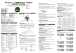
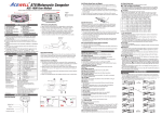
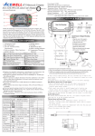
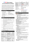
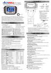
ATV/Motorcycle/Scooter Computer ACE-5XXX User Manual Grazie per aver acquistato il computer Acewell per del moto, Atv e scooter: questo manuale è specificamente progettato per la serie ACE-5XXX. La serie ACE-5XXX comprende ACE-51XX/52XX, 55XX/56XX e ACE-57XX/58XX, le descrizioni conxil simbolo "*" si riferiscono solo alle serie ACE-55XX/56XX e ACE-57XX/58XX, invece le funzioni e le descrizioni con il simbolo "**" sono per la serieACE-57XX/58XX solo. Ogni serie ha diversi modelli, ogni modello ha diversi indicatori a LED. Potreste notare che la foto ha una serie di indicatori LED diversi dalla vostra strumentazione originale, la foto però è solo di riferimento. *Voltage Meter Manutenzione Maximum speed Maximum RPM *Temperatura massima Indicatore di marcia *Durata percorrenza *Tempo in accelerzione *Tempo di decelerazione Barra livello carburante MAX SPD MAX RPM MAX Trip RT SPD RT d SPD RT *Temperatura a barre **Tempo su giro Input potenza Sensore contagiri Sesore velocità PANEL DESCRIPTIONS 1. Scala contagiri 2. Contagiri a barre 3. Indicatore temperatura a barre* 4. 1a riga: contachilometro 5. 2 a riga: altre funzioni 6. Indicatori Led 7. Tasto RESET 8. Tasto MODE 9. Indicatore di marcia 10. Bar Fuel gauge 11. Indicatore temperatura esterna 12. Internal/external control indicators FEATURES Visualizza contemporaneamente tachimetro, contachilometri, indicatore di marcia, indicatore livello carburante e temperatura *a barre grafiche ed un’altra funzione contemporaneamente. L’indicatore di marcia viene calcolata mettendo a confronto la velocità ed I giri motore RPM.L’indicatore di marcia può essere impostato su OFF per I veicoli automatici. In alcuni veicoli la retroilluminazione può essere controllata separatamente dalla messa in moto (accensione motore). Barra grafica contagiri con scala opzionale 10,000rpm o 20,000rpm. Permette all’utente di impostare il contachilometri quando questo è sotto i 30 km, superati i quali la distanza resta salvata in memoria, anche ad apparecchio spento. *Acceleration and deceleration timers as well as distance timer for racing practice. ** Features a 99 lap timer and an optional cable connected remote control switch. Include 6-9 LED per indicare diverse applicazioni a seconda dei modelli. Fast processor so can connect to pulse type gearbox speed sensors. Settaggio circonferenza ruota universale: 1-3999mm. L’indicatore di carburante dispone di tre diverse resistenze in entrata a 100, 250 e 510 Ohm, impostabile anche su OFF per non visualizzare la funzione. Include staffa, cavo RPM, sensore velocità, sesnore temperatura*, kit di montaggio, cablagio, ** telecomando via cavo, istruzioni e garanzia. Designe che garantisce eccellente impermeabilità, una struttura antivibrazione ed immunità al rumore del 100%. **Il ricevitore EM & IR ed il trasmettitore IR per il rilevamento in automatico dei tempi sono disponibili come accessory. SPECIFICATIONS Funzioni Barra contagiri Simbolo bar Contachilometro Km/H or MPH TRIP 1&2 ODO Distanza parziale 1&2 Odometro Orologio 12/24 ore Contagiri digitale * Temperatura esterna Average speed Tempo utilizzo veicolo Tempo totale utilizzo veicolo Ore utilizzo veicolo rpm AVG SPD RT TT HRT Specifiche 500-10,000 rpm/ 1,000-20,000rpm options 2.4-399.9 km/h (248.5 MPH) 0.0-999.99 KM/Miles 0.0 – 999,999 KM, 0.0-621,387 Miles 0:00’ – 11H59’59”/23H59’59” 10-19,990 rpm, 10rpm increment +25℃-180℃ / 77℉-356℉ 2.4-399.9 KM/h (248.5 MPH), 0-99H59`59`` 0-9999H59’ 0-9999H59’ Settaggio circonferenza ruota Speed input divider setup Massima frequenza softwar Dimensioni *Sensore temperatura **Sensore tempo su giro LAP 8.0-18.0 Volt 0-9999H / 0-9999km(6213Miles) 2.4-399.9 Km/h (248.5 MPH), 10-19,990 rpm, 10rpm increment +25℃-180℃ / 77℉-356℉ N, R, 1, 2,…8 gears and off mode 0-1/4 mile. 0-100M, 0-400M 0-100km/h, 50-70mph 100kmh-0kmh +/-100Ω, 250Ω, 510Ω, or off mode 1-7 Bar-graphic 99 Laps. DC 12V CDI o segnale bobina d’accensione Sensore Reed o 2 fili ad effetto Hall con magnete 1mm-3999mm (1mm increment) 1-199 Pulses 7K Hz 130.1mm x82.8mmx27.0 mm Sensore termico Push button or optional accessory spare parts of IR receiver/Magnetic Field sensors. INSTALLATION & PARTS RPM sensor mounting: RPM Input, Either one 1. Signal intensity from ignition coil is dependent on vehicle type. 2. Coil 2-5 turns around spark plug lead, with more turns creating steadily stronger signal, fewer turns creating weaker signal. 3. The RPM circuit is designed for most bikes, however some bikes’ signal is too strong if the RPM looks like much more than actual RPM and unstable, please connect the included 1M Ohm resistor in series to solve it. SPEED SENSOR Mounting: ACEWELL has several speed sensors; the unit may include one of them. If the model is intended to be connected to a gearbox electronic speed output to obtain the speed reading, no speed sensor will be included. Reed Speed Sensor and Magnet: 1. This sensor is universal sensor for motorcycle, find a rotating part to install magnet (for example disk, sprocket or driveshaft) and a location to install the sensor where it can be aligned to the magnet. 2. Align the center of the magnet to either of the sensor marking lines or the side of the sensor. The magnet must not travel down the body of the sensor 3. Installing the sensor parallel to the vibration direction creates optional anti-vibration effect. 4. Make sure the gap between the magnet and the sensor is within 8mm. Hall Effective Speed Sensor and Magnet: 1. This is universal sensor for ATV front or rear wheel installation or motorcycle front wheel installation. For some fitments an accessory speed sensor holder may need to be purchased. 2. Find a rotating part to install magnet (for example disk, sprocket or driveshaft) and a location to install the sensor where it can be aligned to the magnet 3. Align the center of the magnet to center of side face of the sensor. 4. Make sure the gap between the magnet and the sensor is within 5mm.. Specific Hall sensors: Cable drive adaptors for most bikes originally fitted with cable driven speedometers or milemeters are available. When using these cables it is necessary to divide the circumference setting by the number of rotations of the cable per rotation of the wheel. *Thermo Sensor and Sensor Tube: 1. The unit includes a water temperature sensor; you have to purchase a suitable water pipe temperature sensor tube to install the sensor easily. 2. Cut the water pipe, insert the temperature tube into the pipe and secure it by attached pipe clamps. 3. Screw the sensor into the tube. 4. If your vehicle is fitted with a thermostat that stops water flowing to the radiator when the engine is cold, you will not get a reading until the thermostat opens **Wire Remote Control Switch Installation: 1. Install the switch arm on handlebar. 2. Install the switch box to one of 3 fixing holes and adjust switch box to a suitable angle. 3. Plug the switch box connector into the main unit matching connector. FUNZIONI Contagiri a barre graficje: Barra grafiche contagiri con scala opzionale 10.000 e 20.000 rpm. Km/H o MPH: contachilometri 1. Visualizza la velocità fino ad un massimo di 399.9 Km/H or 248.5 MPH. 2. La frequenza massima del software è di 7K Hz. 3. La velocità può essere minore di 399.9 KM/H, nel caso in cui si utilizza il divisore del software, ad esempio la velocità visualizzato sarà 250KM/H nel caso in cui il software è impostato a 105P e la circonferenza ruota a 1277mm. RPM: contagiri digitale 2. Visualizza il contagiri fino ad un massimo di 19,990RPM. Il displays visualizzerà 19,999rpm anche quando il valore supera i 20,000rpm.. 3. Il segnale RPM può essere acquisito sia dal CDI che direttamente dalla bobina. RPM: avviso di cambiata 1. Questa funzione permette di impostare un valore RPM a cui corrisponde un avviso di cambiata. 2. Il contagiri con grafico a barre led il Led lampeggiano quando I giri raggiungono il valore impostato e smettono di lampeggiare una volta cambiata marcia. MAX RPM: contagiri max Visualizza il valore più alto raggiunto dal contagiri dopo l’operazione di azzeramnento. MAX SPD: indicatore di velocità Visualizza il valore più alto raggiunto dopo l’operazione di azzeramento. AVG SPD: indicatore di velocità media Calcola la velocità media dall’ultima operazione di azzeramento. L’ AVG viene calcolato dal TRIP diviso l’ RT. ODO: Odometro 1. La funzione ODO somma la distanza totale durante il funzionamento dell’ATV. 2. I dati della funzione ODO possono essere variati fino al raggiungimento dei 30km (18.6 Miles), superati i quali I dati restano salvati in memoria. RT: tempo di percorrenza 1. Calcola il tempo totale di funzionamento dall’ultima operazione di azzeramento. 2. Il conteggio ha inizio automaticamente con il movimento. TT: Tempo di percorrenza totale 1. Calcola il tempo di funzionamento totale dall’inizio del funzionamento dell’ ATV 2. I dati TT restano salvati in memoria e non possono essere modificati. HRT: Hour Meter 1. Calculates total engine operation time from last RESET. 2. Count automatically begins with engine starting. 3. HRT data is stored in memory, and couldn’t be reset. : Orologio a 12/24 ore Visualizza l’ora corrente nel formato 12 o 24 ore Temperatura a barre grafiche*: : promemoria di manutenzione Conta alla rovescia il tempo inserito o la distanza dall’ultimo RESET. 2. Si accende quando il conteggio è terminato e quindi arrivato a “0”, il simbolo “ ” lampeggia per ricordarvi di controllare olio e le parti. 3. Premere il tasto RESET per ripristinare e riavviare il promemoria dopo la manutenzione. : voltaggio tensione digitale Controlla l’amperaggio della moto e del sistema stesso. 1. :Indicatore di marcia 1. L’indicatore di marcia ha un filo per ogni ingranaggio N e R, collegare come prima cosa ogni filo ad N e R. 2. L’indicatore di marcia viene calcolato dalla somma dell’ RPM e della velocità 3. L’utente deve posizionare ogni ingranaggio prima dell’uso TRIP RT: Timer TRIP Test 1. La funzione di viaggio RT può essere impostato da 100 a 400metri. 2. L’unità calcola la durata dallo START fino al punto prestabilito.Una volta raggiunto il traguardo, si spegnerà automaticamente. SPD RT 1: test di accelerazione 1. La funzione SPD RT 1 può essere impostato da 0-100Km/H per la prova di accelerazione. 2. L’unità calcola il test di accelerazione dallo START fino al punto prestabilito. Una volta raggiunto, si spegnerà automaticamente. SPD RT 2: test di decelerazione 1. La funzione SPD RT 2 può essere impostato da 100 to 0Km/H per la prova di decelerazione. 2. L’unità calcola il test in decelerazione dopo il raggiungimento dei 100 Km/h e dopo il blocco della moto di 2 secondi. Livello carburante 1. Dispone di 7 barre grafiche per la visualizzazione . 2. Built-in 100, 250, 510Ohm, oFF, -100, -250 and -510 Ohm fuel sender resistance, the fuel bars will disappear when you select “oFF” mode. 3. The full bars are low resistance and empty bar is high resistance for 100, 250 and 510ohm; -100, -250 and -510 ohm are the inverse. 4. Last bar flashes to indicate low fuel level automatically. Fuel Bar 7 6 5 4 3 2 1 0-Flash 100Ω 0~10 11~20 21~35 36~45 46~60 61~75 76~90 91~100 250Ω 0~25 26~50 51~85 86~110 111~150 151~200 201~230 231~250 510Ω 0~50 51~100 101~180 181~230 231~300 301~380 381~460 461~510 -100Ω 100~90 89~75 74~60 59~45 44~35 34~20 19~10 9~0 -250Ω 250~230 229~200 199~150 149~110 109~85 84~50 49~25 24~0 -510Ω 510~460 459~380 379~300 299~230 229~180 179~100 99~50 49~0 LAP**: Lap Timer 1. It can keep up to 99 sets of lap timer. 2. The function must be operated by an additional wiring remote control switch or an accessory IR receiver/transmitter or a magnetic field sensor. BUTTON OPERATIONS MODE Button 1. Press the MODE button to move between all functions in sequence as “→” from one function screen to another when the speed sensor does not detect any signal input. Trip 1-Trip2- ODO- CLK – RPM – TEMP – AVG SPD – RT – TT – HRT – VOLTG-Maintain reminder - MAX SPD – MAX RPM – MAX TEMP – Trip 1 2. Press the MODE button to move partial functions in loop sequence as “ =>”when speed sensor detects signal input. 1.Dispone di 7 barre per la visualizzazione della temperatura. 2.The 4th bar counts from bottom be turned on and over temperature LED flashes when thermometer reaches the preset warning temperature, each +/15℃ lights on/off a bar base on the 4th bar. 3.La barra grafica lampeggierà quando la temperatura misurata sarà superiore alla misura attuale. : temperatura digitale motore * 1. Il displays visualizza -L-℃ or -L-℉ quando la temperatura è inferiore a 40℃ or 104℉, e -H- ℃ or –H-℉ quando la temperatura è maggiore a 180℃ o 356℉. 2. Le schermo LCD lampeggerà quando la temperatura rilevata sarà superiore alla temperatura massima impostato. . MAX : temperatura massima* Indica la temperatura massima raggiunta dall’ultimo azzeramento. RESET Button 1. Press RESET button acts as a revised button operation of MODE button. 2. Press MODE or RESET button to the desired screen then press RESET button for 2 seconds to reset TRIP 2, MAX SPD, MAX RPM and MAX data from stored values to zero individually. The maintain reminder data will be reset to the preset value rather than zero. 3. The data of Trip 1, AVG & RT will all be reset at the same time when one of the 3 data functions is being reset. 4. ODO, clock, HRT and TT data cannot be reset. Shift Warning RPM Operation 1. Press MODE button to the RPM screen; pull on the throttle until the desired shift warning RPM. 2.Press RESET button to confirm and set up the shift warning RPM. 3.Bar-graphic tachometer and warning LED will flash to warning you shift gear. 4.Press RESET button for 2 seconds at the RPM screen to re-adjust the shift warning RPM. Gear Indicator training operations: 1. Connects grey wire to N and purple wire to R. 2. Put bike to a rolling stand, turns on engine and keep at N gear. 3. Gear indicator shows “N” 4. Change the LCD screen to digital RPM. 5. Press and hold MODE button for 2 seconds to go into the number of gears setting mode. 6. Gear indicator flashes the default 6 gears. 7. Press RESET button to select the number of gear, user can select 4-8 gears or “0” to disable the gear function. 8. Press MODE button to confirm the number of gears and go to the number gear ratio setting mode. 9. It displays and flashes “1”, shift bike’s gear to the 1st gear, run the engine to between 2000-4000RPM. 10. Hold the speed and the RPM for about 5 seconds until the “-“flashing. The flashing “-“ after the gear “1” means the 1st gear be set. 11. Press MODE button to confirm the set and go to the 2nd gear setting. 12. It displays and flashes “2”, shift bike’s to the 2nd gear, run the engine to between 2000-4000RPM. 13. Hold the speed and the RPM for about 5 seconds until the “-“flashing. The flashing “-“ after the gear “2” means the 2nd gear be set. 14. Press MODE button to confirm the setting and go to next gear setting. 15. Operates the same operations as items 11-14 to set other gears until the last gear be set. Press MODE button to return to normal mode. 16. At gear indicator setting mode, press and hold MODE button for 2 seconds to abort the setting if you need to re-set at any setting screen. *TRIP RT, SPD RT1 and SPD RT2 setting mode 1. Press MODE or RESET button to the TT screen, press and hold MODE button for 2 seconds to go into the 3 test timers set mode. 2. It displays SELECt and flashes TRIP RT, press MODE button to move SPD RT 1, SPD RT 2 and TRIP RT from one set mode to another set mode in loop sequence, press RESET button at the one of the 3 screens to go into the mode to be set. 3. At TRIP RT set mode, it displays TRIP RT and flashing “100”, each press of MODE button converts 100 or 400meter to be tested, press RESET button to confirm the setting and go into the trip timer testing screen and flashing 00:00:00, the timer counts automatically when it receive speed signal and auto-stop when trip meter reaches preset 100 or 400 meter. Press RESET button to reset the tested timer and preparing another new rund test, it displays TRIP RT and flashes 00:00:00 again. Press and hold MODE button for 2 seconds to go out the TRIP RT test screen and return to TT screen. 4. At SPD RT 1 set mode, it displays SPD RT 1 and flashing “0-100”, press RESET button to confirm the setting and go into the acceleration timer testing screen and flashing 00:00:00, the timer counts automatically when it receive speed signal and auto-stop when speed reaches preset 100Km/H. Press RESET button to reset the tested timer and restart a new test, it displays SPD RT 1 and flashes 00:00:00 again. Press and hold MODE button for 2 seconds to go out the SPD RT 1 test screen and return to TT screen. 5. At SPD RT 2 set mode, it displays SPD RT 2 and flashing “100-0”, press RESET button to confirm the setting and go into the acceleration timer testing screen and flashing 00:00:00, speed the bike/vehicle up to more than 100km/h the decreased the speed, the timer counts automatically when it speed is less than 100km/h and auto-stop after 2 seconds of the bike/vehicle stop then count back 2 seconds automatically. Press RESET button to reset the tested timer and restart a new test, it displays SPD RT 2 and flashes 00:00:00 again. Press and hold MODE button for 2 seconds to go out the SPD RT 2 test screen and return to TT screen. . **Remote Control Switch for LAP timer: 1. The remote control switch has 2 buttons: MODE and LAP. The MODE button has the same function as on the main unit. 2. Press and hold the LAP button for 2 seconds to go into the LAP mode. 3. LAP Record operations: 4. In LAP mode, press LAP button to start the LAP recording function, each press of MODE button records a set of data LAP & AVG and displays LAP timer for 3 seconds then changes display to speed mode automatically, press LAP button to convert stop or start LAP record function, press and hold the LAP button for 2 seconds to go out LAP mode and return to normal mode. **LAP review operations: 1. In the LAP mode, press MODE button to review the 1 st storage data, it displays number of lap and lap timer. 2. Press the RESET button to switch between lap timer or average speed of the same LAP; each press of the MODE button displays data for the next lap. 3. Press and hold LAP buttons for 2 seconds to go out LAP mode and return to normal mode. WHEEL CIRCUMFERENCE TABLE 1. The details below have been calculated using following formula: Tire Diameter (inches) x 25.4(mm/inches) x 3.1416 = wheel circumference (in mm). 2. Identify the tire size of your ATV/Motorcycle when you need to change different tire size and key in the corresponding number shown in the following chart. Tire Size Circumferen Tire Size Circumferen Tire Size Circumferen ce number ce number ce number (mm) (mm) (mm) 3. 4. 5. 6. 7. 15 inch 1197 19 inch 1516 23 inch 1835 16 inch 1277 20 inch 1596 24 inch 1915 17 inch 1357 21 inch 1676 25 inch 1995 18 inch 1436 22 inch 1756 26 inch 2075 These values are approximate and will differ for different brands of tire, we would always recommend that you measure the distance travelled per revolution of the wheel in mm and enter this into the computer. The computer calculates the wheel rotating length between 2 passes of the magnet; use this table to find the settings when you are using a reed sensor or an universal hall sensor with magnet to measure your speed. If you are using a cable drive speed sensor then divide the number in the above table by the number of turns of the cable drive for each revolution of the wheel. For example if 1 wheel revolution equals 5 turns of speed cable then the wheel circumference has to be divided 5. You can use more magnets, but the wheel circumference setting must be divided by the number of magnet you installed. The computer has a built-in software divider setting from 1 to 199 for different speed signal application, refer to the divider setup, one means one wheel revolution creates one signal. You have to input the number of signal per wheel revolution to have a correct speed. Clock, RPM, Wheel, Divider, Unit, Maintain, Thermometer, fuel meter and ODO Setup 1. Setup operations include 12/24hour clock, bar rpm scale, shift warning RPM, numbers of engine rotation per signal, wheel circumference, signal divider, units, decimal, maintain reminder, *units of temperature, *temperature warning, fuel meter input resistance selection and odometer adjustment. These must be set up step by step. The computer will be automatically revert to normal mode if no button is pressed for 75 seconds at any setting screen. 2. Press both MODE & RESET buttons to go into setting mode. In setting mode, each press of the RESET button increments the flashing digit by 1 or converts units. Press MODE button to confirm the digit setting and jump to next digit or next setting screen to be set. Press MODE button for 2 seconds at any setting screen to finish the setting and go to normal mode. 3. It displays "12 or 24H, and XX:XX-XX" symbols as well AM/PM in case you select 12H. Operates buttons as descriptions of item 2 to finish clock setting and jump to 10,000/20,000rpm scale setting. 4. It displays 10,000rpm scale, press RESET button to convert 1TO BE SET 0,000 or 20,000rpm. Press MODE button to confirm the setting and jump to shift RPM warning setting. 5. It displays the default "RPM r06500", the digit “0” flash. Follow the item 2 of button operation to finish the shift RPM warning setting and jump to engine specification setting. 6. It displays "RPM SPC-X.X", the default value is 1.0; there are 4 options: 1.0, 2.0, 3.0 and 0.5. It means the numbers of engine rotation per signal. For example the value 2.0 means the engine rotate 2 turns to output a signal. 7. Press RESET button to move in loop sequence from one to another value of the 4 values. Press MODE button to confirm the setting and go to wheel circumference setting screen. 8. In "SPD cXXXX" display, "c" means "Circumference", following 4 default digits; flashing digit is digit to be set. Follow the item 2 of button operation to finish the wheel circumference setting and jump to signal divider setting. 9. It displays "SPD P-001" for signals to be divided. Follow item 2 of button operation to finish the setting and jump to unit setting. 10. It displays KM/H or MPH, each press of RESET button converts unit; press MODE button to confirm unit setting and jump to decimal point setting. 11. It displays “99.9 & on” or “99 & oFF”, the decimal point will be disappeared in case Off is selected. Follow the item 2 of buton operation to finish the decimal setting and jump to maintain reminder setting. 12. It displays and RT, TRIP or OFF, RT has default of 100 hours, TRIP has 1000km (621Miles) default. Follow the item 2 of button operation to finish the maintain reminder setting and jump to thermometer unit setting. The maintain reminder function will be disappear when select “OFF”. 13. 14. 15. 16. 17. It displays " ℃ , ℉ or oFF", each press of RESET button converts ℃, ℉ or Off, the temperature bars will disappear when you select oFF mode; press MODE button to confirm temperature setting and jump to temperature warning setting. It displays " XXX" and the selected unit. Follow the item 2 of button operation to finish the temperature warning setting and go to fuel sensor resistance setting. It displays “100r” and fuel tank symbol, follow the item 2 to select 100, 250, 510ohm, Off, -100r, -250r or -510r and jump to sensor type of LAP timer setting. The fuel meter bar will disappear if you select oFF mode. *It displays Ir, EF1, EF2 or EF3, Ir means you elect IR receiver as the sensor of LAP timer, and the selection of EF1, 2 or 3 is a magnetic field sensor for LAP timer, the number of 1, 2 or 3 is means the number of magnetic sensor in track, for example EF2 means the track has 2 magnetic sensor and it will combine 2 sensing signals in one. Follow the item 2 to set sensor type of LAP timer and jump to odometer setting. It displays “ODO & 00000X km”, the “X” is from odometer testing in factory, follow item 2 to setting a desired odometer and jump to clock setting or return to Normal Mode. This setting screen will disappear when the odometer is over 30km (18.6Miles) or your setting is over 30km Press 2 Seconds. Mode Button, RESET Button, MODE Reset, Mode + Reset 2 seconds.