1
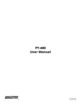
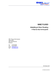
LPU-2428 & RST-4001 User Manual APG R Doc #9002999 Rev B1, 04/15 Table of Contents Introduction................................................................................................................. iii Warranty and Warranty Restrictions..................................................................... iv Chapter 1: Specifications and Options..................................................................... 1 Dimensions.........................................................................................................................................1 Specifications.................................................................................................................................... 2 Chapter 2: Installation and Removal Procedures and Notes...............................3 Tools Needed...................................................................................................................................... 3 Installation Notes............................................................................................................................. 3 Mounting Instructions.................................................................................................................... 4 Electrical Installation...................................................................................................................... 4 Software Installation........................................................................................................................ 5 Removal Instructions...................................................................................................................... 5 Chapter 3: Maintenance..............................................................................................5 General Care....................................................................................................................................... 5 Troubleshooting................................................................................................................................ 6 Calibration...................................................................................................................................... 6-7 Repair and Returns........................................................................................................................... 7 Chapter 4: Programming and Parameter Configuration......................................7 RST-4001 User Interface.................................................................................................................. 7 RST-4001 Menu Navigation....................................................................................................... 8-11 Software User Interface................................................................................................................. 12 Programming the LPU-2428......................................................................................................... 13 Basic Setup Menu (BASICSET)............................................................................................... 14-15 App. Setup Menu (APPLICAT).................................................................................................16-34 4-20 Setup Menu (4-20 SET)................................................................................................... 34-36 Calibration (CALIBRAT)........................................................................................................... 36-37 Advanced (ADVANCED)........................................................................................................... 37-39 Utilities (UTILITIE)................................................................................................................... 39-40 Totalization (TOTALIZE)................................................................................................................ 41 Chapter 5: Hazardous Location Drawing and Certification...............................42 Intrinsically Safe Wiring Diagram..............................................................................................42 Hazardous Location Wiring Diagram......................................................................................... 43 CSA Certificate of Compliance............................................................................................... 44-47 IMPORTANT: The LPU-2428 software will only operate in a 32-bit Windows environment. It WILL NOT operate on a 64-bit Windows machine. ii Tel: 1/888/525-7300 • Fax: 1/435/753-7490 • www.apgsensors.com • [email protected] Introduction Thank you for purchasing an LPU-2428 ultrasonic sensor and RST-4001 programming module from APG. We appreciate your business! Please take a few minutes to familiarize yourself with your LPU-2428, RST-4001, and this manual. The LPU-2428 loop-powered ultrasonic sensor provides a low-power, non-contact level measurement solution rated for hazardous locations and suitable for harsh chemical environments. The RST-4001 offers a two-line by eight-character LCD display and five-button keypad or USB connection for programming your sensor. The default Application setting for the LPU-2428 is Distance, which will work in a wide variety of settings. The LPU-2428 has several additional Application settings that can be configured to meet your needs. Reading your label Every APG instrument comes with a label that includes the instrument’s model number, part number, serial number, and a wiring pinout table. Please ensure that the part number and pinout table on your label match your order. The following electrical ratings and approvals are also listed on the label. Please refer to the Certificate of Compliance at the back of this manual for further details. Electrical ratings Input: 12 to 28 Volts DC; Output: 4-20mA Class I Division 1; Groups C, D T3 Class I, Zone 0, Group IIB AEx ia IIB T3 (USA): Ta: -40°C to 60°C; IP65 Ex ia IIB T3 (Canada): Ta: -40°C to 60°C; IP65 Vmax Ui= 28VDC, Imax Ii = 130mA, Pmax Pi = 0.91W, Ci = 0nF, Li = 110μH Install in accordance with drawing 9002747 (page 42). Input: 12 to 28 Volts DC; Output: 4-20mA Class I Division 2; Groups C, D T6 Class I, Zone 2, Group IIB AEx nA IIB T6: Ta: -40°C to 60°C; IP65 Ex nA IIB T6: Ta: -40°C to +60°C; IP65 Install in accordance with drawing 9002745 (page 43). IMPORTANT: Your LPU-2428 MUST be installed according to drawing 9002747 as indicated above to meet Instrinsically Safe approvals. Faulty installation will invalidate all safety approvals and ratings. Tel: 1/888/525-7300 • Fax: 1/435/753-7490 • www.apgsensors.com • [email protected] iii Warranty and Warranty Restrictions APG warrants its products to be free from defects of material and workmanship and will, without charge, replace or repair any equipment found defective upon inspection at its factory, provided the equipment has been returned, transportation prepaid, within 24 months from date of shipment from factory. THE FOREGOING WARRANTY IS IN LIEU OF AND EXCLUDES ALL OTHER WARRANTIES NOT EXPRESSLY SET FORTH HEREIN, WHETHER EXPRESSED OR IMPLIED BY OPERATION OF LAW OR OTHERWISE INCLUDING BUT NOT LIMITED TO ANY IMPLIED WARRANTIES OF MERCHANTABILITY OR FITNESS FOR A PARTICULAR PURPOSE. No representation or warranty, express or implied, made by any sales representative, distributor, or other agent or representative of APG which is not specifically set forth herein shall be binding upon APG. APG shall not be liable for any incidental or consequential damages, losses or expenses directly or indirectly arising from the sale, handling, improper application or use of the goods or from any other cause relating thereto and APG’s liability hereunder, in any case, is expressly limited to the repair or replacement (at APG’s option) of goods. Warranty is specifically at the factory. Any on site service will be provided at the sole expense of the Purchaser at standard field service rates. All associated equipment must be protected by properly rated electronic/electrical protection devices. APG shall not be liable for any damage due to improper engineering or installation by the Purchaser or third parties. Proper installation, operation and maintenance of the product becomes the responsibility of the user upon receipt of the product. Returns and allowances must be authorized by APG in advance. APG will assign a Return Material Authorization (RMA) number which must appear on all related papers and the outside of the shipping carton. All returns are subject to the final review by APG. Returns are subject to restocking charges as determined by APG’s “Credit Return Policy”. iv Tel: 1/888/525-7300 • Fax: 1/435/753-7490 • www.apgsensors.com • [email protected] Chapter 1: Specifications and Options • Dimensions NON-METALLIC STRAIN RELIEF 3/4" NPT THREADS 7.25 [184.15 mm] 2" NPT THREADS 2.65 [67.24mm] 5.06 [128.59 mm] ø2.79 [70.78mm] ø2.00 [50.80 mm] Tel: 1/888/525-7300 • Fax: 1/435/753-7490 • www.apgsensors.com • [email protected] 1 • Specifications Performance Operating Range Analog Output (Sensor) Analog Output (Module) Beam Pattern Frequency Response Time Sample Rate 1 - 25 ft. (0.3 - 7.6 m) on liquids and hard, flat surfaces 1 - 10 ft. (0.3 - 3 m) on bulk solids 4-20 mA USB 9° off axis 69 kHz 0.6 - 3 seconds (dependent on output range) 3 seconds @ 4 mA 0.6 seconds @ 20 mA Accuracy Accuracy Resolution ±0.25% of detected range 0.1 inch (2.54 mm) Environmental Operating Temperature Internal Temperature Compensation Enclosure Protection NEMA rating (Sensor) -40 to 60°C (-40 to 140°F) Yes IP65 4X Electrical Supply Voltage (at sensor) 12-28 VDC Current Draw22 mA max Output Signal3-30 mA max Load Resistence 150Ω max @ 12 VDC 600Ω max @ 24 VDC Cable Connection (Sensor) 2-wire cable included Cable Connection (Module) 2-terminal Pheonix connector, USB Masterials of Construction 2 Transducer Housing Upper Housing (Sensor) Housing (Module) PVDF (Kynar®) PC/PBT ABS PA-756 Tel: 1/888/525-7300 • Fax: 1/435/753-7490 • www.apgsensors.com • [email protected] Chapter 2: Installation and Removal Procedures and Notes • Tools Needed Tools are not necessary for installing the LPU itself. If you are using a stand pipe to mount your LPU, you will probably need tools to install the stand pipe, but not for the LPU. • Installation Notes • Mount your LPU sensor so that it has a clear, perpendicular sound path to the surface being monitored. Your sensor should be mounted away from tank or vessel walls and inlets. See Figure 2.1. • The sound path should be free from obstructions and as open as possible for the 9° off axis beam pattern. • If you are using a stand pipe, please see our guide to stand pipes on our website: http://www.apgsensors.com/about-us/blog/how-to-install-a-stand-pipe. Figure 2.1 NOTE: Do not mount the sensor where the beam will intersect objects such as fill streams, pipes, ladder rungs, wall seams, or corrugated tank walls. Tel: 1/888/525-7300 • Fax: 1/435/753-7490 • www.apgsensors.com • [email protected] 3 • Mounting Instructions Mounting your LPU is easy if you follow a few simple steps: • Never over-tighten the sensor. • Always screw in your sensor by hand to avoid cross-threading. Thread failure can be a problem if you damage threads by over-tightening them or by crossing threads. IMPORTANT: Do not over tighten! The sensor should be threaded in only hand tight. • Electrical Installation For normal operation, connect the provided cable to your control system: • Connect the red wire to +24 VDC. • Connect the black wire to 4-20 mA input. Circuit load resistance + input resistence must be greater than 150Ω. 249Ω is recommended for optimal signal tranmission. • Refer to drawing 9002747 (page 42) for Intrinsically Safe installation. • Refer to drawing 9002745 (page 43) for hazardous location installation. For programming: • Connect (+) terminal of RST-4001 to +24 VDC supply of sensor (red wire). • Connect (-) terminal of RST-4001 to 4-20 mA signal from sensor (black wire). • Ensure that load resistor is between RST-4001 and control network or PLC, rather than between sensor and RST-4001. (See Figure 2.2) 4 to 20ma Out +24vdc 4-20ma IS Barrier Power Supply (24Vdc) 4.25 Ammeter COM mA Terminal Strip (Provided) + - Load Resistor APG I/0 Computer USB Cable Figure 2.2 4 Tel: 1/888/525-7300 • Fax: 1/435/753-7490 • www.apgsensors.com • [email protected] • Software Installation • • • • • Download the software zip file from http://apgsensors.com/support. Open the zip file. Choose “Install” from the options at the top of the zip file window. The installation process will prompt you as needed to complete the installation. The software will create and run from a folder in your start menu titled “APG”. IMPORTANT: The LPU-2428 software will only operate in a 32-bit Windows environment. It WILL NOT operate on a 64-bit Windows machine. • Removal Instructions • • • • Ensure that power to the sensor is off. Disconnect the cable from the sensor. Remove the sensor and store it in a dry place, at a temperature between -40° F and 180° F. If the sensor was installed in a hazardous location, ensure that the cable will not be energized while the sensor is disconnected. DANGER: Do not disconnect equipment installed in hazardous locations unless power has been switched off or area is known to be non-hazardous. Chapter 3: Maintenance • General Care Your LPU-2428 ultrasonic sensor is very low maintenance and will need little care as long as it was installed correctly. However, in general, you should: • Avoid applications for which the sensor was not designed, such as extreme temperatures, contact with incompatible corrosive chemicals and fumes, or other damaging environments. • Inspect the threads whenever you remove the sensor from duty or change its location. Tel: 1/888/525-7300 • Fax: 1/435/753-7490 • www.apgsensors.com • [email protected] 5 • Trouble Shooting Should you have problems with your LPU-2428, here are some troubleshooting steps. • Check the received signal strength (just to left of the three Help buttons in the lower right corner. See Figure 4.32). If the signal strength is low, alternately increase Pulses and Sensitivity (Figure 4.30) until the signal strength improves. • Ensure Temperature Compensation (Figure 4.30) is turned on. • Set the Gain Control to AutoSense (Figure 4.30). • Ensure that Blanking (Figure 4.30) is accurately set to account for any unwanted targets between the sensor and the closest acceptable target. • Ensure that the LPU-2428 software is installed in a 32-bit Windows environment. Although the software will install in a 64-bit environment, it will not operate. IMPORTANT: The LPU-2428 software will only operate in a 32-bit Windows environment. It WILL NOT operate on a 64-bit Windows machine. • Calibration This procedure uses targets at known distances to calibrate the sensor’s accuracy. A wall or other large, flat object is recommended for the long range target. • Point the sensor at a target at a known distance near the maximum range of the sensor, 25’ for a single solid object (See Figure 3.1). • Adjust the Multiplier value until the distance reading on the sensor matches the actual measured distance to the target (See Figure 4.29). • Point the sensor at a target near the minimum measurement range, 1’ plus any Blanking distance (See Figure 3.2). • Adjust the Offset value until the distance reading on the sensor matches the actual measured distance to the target (See Figure 4.29). • Repeat previous two steps until no further adjustment is required. measure measure Figure 3.1 6 Tel: 1/888/525-7300 • Fax: 1/435/753-7490 • www.apgsensors.com • [email protected] Figure 3.2 NOTE: The Reset parameter in the Utilities Menu (Figure 4.31) will reset the LPU-2428 to factory default settings. • Repair and Returns Should your LPU-2428 ultrasonic sensor require service, please contact the factory via phone, email, or online chat. We will issue you a Return Material Authorization (RMA) number with instructions. • Phone: 888-525-7300 • Email: [email protected] • Online chat at www.apgsensors.com Please have your LPU-2428’s part number and serial number available. See Warranty and Warranty Restrictions for more information. Chapter 4: Programming and Parameter Configuration • RST-4001 User Interface The RST-4001 user interface is made up of a two-line by eight-character LCD screen and five buttons. (See Figure 4.1) The LCD display shows the current measurement (Distance is the default Applicaiton setting). The display is also used to navigate menus, and view and edit parameters when programming. Menus appear on the top line in ALL CAPS. Parameters cycle on the bottom line with Initial Caps. Parameter values are shown on the top line, and are numeric values or ALL CAPS. The LPU has five programming or navigation buttons, LEFT Arrow, RIGHT Arrow, UP Arrow, DOWN Arrow, and I/O (Enter). The arrow buttons allow the user to move through the menus in order to access and change parameters. Pressing the I/O button saves the displayed value of a parameter. Tel: 1/888/525-7300 • Fax: 1/435/753-7490 • www.apgsensors.com • [email protected] Figure 4.1 7 • RST-4001 Menu Navigation To select a menu, press the UP Arrow or DOWN Arrow button until the desired menu is displayed. Press the Right arrow to move into that menu. Then press the UP or DOWN Arrow button to move to the desired parameter. To view or change a parameter value, press the RIGHT Arrow button. The display will show the name of this parameter on the lower line and the current value on the upper line of the display. To change the parameter’s value, press the UP Arrow or DOWN Arrow button until the desired value is displayed. To store or save the changed value, press the I/O button once. At this point, the parameter value has been saved to the LPU. The values are stored in nonvolatile memory, and will not be lost when power is turned off. For a full explanation of each menu and parameter, see pages 13 - 41. Main Menus and BASICSET Menu BASICSET Units Feet Inch Meters MM APPLICAT 4-20 SET Out Func DISTANCE LEVEL VOLUME FLOW LIN TABL SUBMERSI CALIBRAT ADVANCED Vol Unit UTILITIE TimeUnit Response V FT^3 V MFT^3 V GAL V M^3 V LIT PER SEC PER MIN PER HOUR PER DAY DISTANCE Out Func APPLICAT Max Dist ically based on selected Out Func. See menu explanations on page 15. Standard Fast Immediat Distance APPLICAT Menu BASICSET NOTE: Menu options change dynam- Level APPLICAT Menu DISTANCE LEVEL VOLUME FLOW LIN TABL SUBMERSI BASICSET 25.00 (ft) 1.000 - 25.00 [12.0 - 300.0] [0.305 - 7.620] [305 - 7620] APPLICAT LEVEL Out Func Ful Dist Emp Dist 8 Tel: 1/888/525-7300 • Fax: 1/435/753-7490 • www.apgsensors.com • [email protected] DISTANCE LEVEL VOLUME FLOW LIN TABL SUBMERSI 1.00 (ft) 0.00 - 25.00 [0.0 - 300.0] [0.000 - 7.620] [0000 - 7620] 25.00 (ft) 1.00 - 25.00 [12.0 - 300.0] [0.305 - 7.620] [305 - 7620] Volume APPLICAT Menu BASICSET VOLUME Out Func APPLICAT TankType Ful Dist Emp Dist T Diamet Rad Hemi Cone Dia Cone Hei T Length T Width C Length C Width C Height Flow - Flume APPLICAT Menu DISTANCE LEVEL VOLUME FLOW LIN TABL SUBMERSI BASICSET FLOW Out Func SCTWHB SCTWCB SRT HCT ST APPLICAT Flume FlowType 1.00 (ft) 0.00 - 25.00 [0.0 - 300.0] [0.000 - 7.620] [0000 - 7620] 25.00 (ft) 1.00 - 25.00 [12.0 - 300.0] [0.305 - 7.620] [305 - 7620] 1.00 (ft) 0.00 - 100.00 [0.0 - 1200.0] [0.000 - 30.480] [0000 - 30480] 1.00 (ft) 0.00 - 25.00 [0.0 - 300.0] [0.000 - 7.620] [0000 - 7620] 1.00 (ft) 0.00 - 100.00 [0.0 - 1200.0] [0.000 - 30.480] [0000 - 30480] 1.00 (ft) 0.00 - 25.00 [0.0 - 300.0] [0.000 - 7.620] [0000 - 7620] 1.00 (ft) 0.00 - 100.00 [0.0 - 1200.0] [0.000 - 30.480] [0000 - 30480] Flume Ty Max Flow ZeroFlow K n (N1) Throat W N2 DISTANCE LEVEL VOLUME FLOW LIN TABL SUBMERSI Flume Weir Equation Parshall CutThroa 1.00 (ft) 0.00 - 25.00 [0.0 - 300.0] [0.000 - 7.620] [0000 - 7620] 1.00 (ft) 0.00 - 25.00 [0.0 - 300.0] [0.000 - 7.620] [0000 - 7620] 1.00 Range varies 1.00 0.00 - 2.00 1.00 (ft) 0.00 - 25.00 [0.0 - 300.0] [0.000 - 7.620] [0000 - 7620] 1.00 0.00 - 2.00 1.00 (ft) 0.00 - 25.00 [0.0 - 300.0] [0.000 - 7.620] [0000 - 7620] 1.00 (ft) 0.00 - 25.00 [0.0 - 300.0] [0.000 - 7.620] [0000 - 7620] 1.00 (ft) 0.00 - 25.00 [0.0 - 300.0] [0.000 - 7.620] [0000 - 7620] 1.00 (ft) 0.00 - 25.00 [0.0 - 300.0] [0.000 - 7.620] [0000 - 7620] Tel: 1/888/525-7300 • Fax: 1/435/753-7490 • www.apgsensors.com • [email protected] 9 Flow - Weir APPLICAT Menu BASICSET FLOW Out Func APPLICAT Weir FlowType Weir Typ Max Flow ZeroFlow K n (N1) Diameter C Length N2 Flow - Equation APPLICAT Menu DISTANCE LEVEL VOLUME FLOW LIN TABL SUBMERSI BASICSET FLOW Out Func Flume Weir Equation APPLICAT Equation FlowType Flume Weir Equation Equation 1 2 3 4 Californ Rect w/c Rect /o Trapazod Triangul 1.00 (ft) 0.00 - 25.00 [0.0 - 300.0] [0.000 - 7.620] [0000 - 7620] 1.00 (ft) 0.00 - 25.00 [0.0 - 300.0] [0.000 - 7.620] [0000 - 7620] 1.00 Range Varies 1.00 0.00 - 2.00 1.00 (ft) 0.00 - 25.00 [0.0 - 300.0] [0.000 - 7.620] [0000 - 7620] 1.00 (ft) 0.00 - 25.00 [0.0 - 300.0] [0.000 - 7.620] [0000 - 7620] 1.00 0.00 - 3.00 Max Flow ZeroFlow K n (N1) Length X Diameter N2 10 Tel: 1/888/525-7300 • Fax: 1/435/753-7490 • www.apgsensors.com • [email protected] DISTANCE LEVEL VOLUME FLOW LIN TABL SUBMERSI 1.00 (ft) 0.00 - 25.00 [0.0 - 300.0] [0.000 - 7.620] [0000 - 7620] 1.00 (ft) 0.00 - 25.00 [0.0 - 300.0] [0.000 - 7.620] [0000 - 7620] 1.000 0.000 - 10e308 1.000 0.000 - 10e308 1.000 0.000 - 10e308 1.000 0.000 - 10e308 1.000 0.000 - 10e308 1.000 0.000 - 10e308 Submersible APPLICAT Menu BASICSET SUBMERSI Out Func APPLICAT Depth SubRange DISTANCE LEVEL VOLUME FLOW LIN TABL SUBMERSI 25.00 (ft) 0.00 - 25.00 [0.0 - 300.0] [0.000 - 7.620] [0000 - 7620] 1.00 (ft) 0.00 - 25.00 [0.0 - 300.0] [0.000 - 7.620] [0000 - 7620] 4-20 SET Menu ADVANCED Menu 4-20 SET MinMaSet MaxMaSet FailSafe FS Delay 1.00 0.00 - 25.00 [0.0 - 300.0] [0.000 - 7.620] [0000 - 7620] ADVANCED TempComp GainCont 20.00 0.00 - 25.00 [0.0 - 300.0] [0.000 - 7.620] [0000 - 7620] Sensitiv 3.8 MA 22 MA Hold Pulses 15 15 - 9999 Blanking CALIBRAT Menu ON OFF AutoSens HardTarg SoftTarg Manual 85% 0 - 100% 16 0 - 16 1.00 (ft) 0.00 - 25.00 [0.0 - 300.0] [0.000 - 7.620] [0000 - 7260] UTILITIE Menu CALIBRAT MinMaVal MaxMaVal Min Trim 4.00 4.00 - MaxMaVal UTILITIE 20.00 MinMaVal - 20.00 LoDisSim HiDisSim 500 0 - 999 SimCycle Max Trim 500 0 - 999 1.00 (ft) 0.00 - 25.00 [0.0 - 300.0] [0.000 - 7.620] [0000 - 7620] 1.00 (ft) 0.00 - 25.00 [0.0 - 300.0] [0.000 - 7.620] [0000 - 7620] Off 10 - 9999 (sec) [Display only] Version Multipli 1.000 0.000 - 1.999 Reset Offset 0.00 (ft) -3.00 - 3.00 Tel: 1/888/525-7300 • Fax: 1/435/753-7490 • www.apgsensors.com • [email protected] No Reset Sensor Total 11 • Software User Interface The LPU-2428 software user interface is one screen with five primary areas (See Figure 4.2). In the upper left are seven Menu Buttons. These buttons control the information viewed in the Display Area. Below the Menu Buttons and Display Area are six Status Boxes in two columns. Under the right hand column of Status Boxes are three Control Buttons. Three Help Buttons are located in the lower right hand corner of the screen. Figure 4.2 The two Status Boxes in the right column show the status of communication between the RST-4001 and the sensor, and between the LPU-2429 software and the RST-4001 (See Figure 4.3). If an error is indicated, then check for proper connections. Allow a moment for the communication to be established while watching the status box to indicate “Sensor Communicating”. If this fails to establish communication, plug the USB cable into another USB port on the computer. After communication is established, click on the “Receive” button to load the sensor settings into the software. Figure 4.3 12 Tel: 1/888/525-7300 • Fax: 1/435/753-7490 • www.apgsensors.com • [email protected] • Programming the LPU-2428 The following menus are used to program the LPU-2428 whether you use the RST-4001 alone, or in conjunction with the LPU-2428 software. As described in the RST-4001 User Interface section above, menus are navigated on the RST-4001 using the UP Arrow and DOWN Arrow, and selected with the RIGHT Arrow. In the LPU-2427 software, menus are navigated by clicking on the desired Menu Buttons on the left side of the screen. Main: Displays distance, level, volume, or flow. A graphical representation is displayed for level, volume, or flow. Basic Setup: Menu contains Units, Application, Flow/Volume Units, Flow Rate, and Response Time. App. Setup: Menu contains parameters specific to the current Application selected in Basic Setup. These include Volume Tank Type, Flow Type, Max/Full Distance, Zero/Empty Distance, and values for flow or volume. 4-20 Setup: Menu contains Min & Max mA Setpoints, Fail Safe, and Fail Safe Delay. Calibration (not required on most applications): Menu contains Min & Max mA Value, Min & Max mA Trim, Multiplier, and Offset. Advanced: Menu contains Temperature Compensation, Gain Control, Sensitivity, Pulses, and Blanking. Utilities: Menu contains Low & High Distance Simulation, Simulation Cycle Time, Reset, File System, and Software Version. Tel: 1/888/525-7300 • Fax: 1/435/753-7490 • www.apgsensors.com • [email protected] 13 • Basic Setup Menu (BASICSET) Figure 4.4 Menu Parameter RST-4001 Options Software Options Basic Units Default = Feet Default = Feet Setup (Units) FeetFeet InchInches Meters Meters MM Millimeters Units (Units on the RST-4001) selects the units of measurement that will be used throughout the setup process and also for display. The selected units also determines the resolution of the display and the outputs. The resolution is: feet 0.01, inches 0.1, 0.000 meters, and millimeters 1. NOTE: All parameter settings use the units selected in Units. 14 Tel: 1/888/525-7300 • Fax: 1/435/753-7490 • www.apgsensors.com • [email protected] Menu Parameter RST-4001 Options Software Options Basic Application Default = DISTANCE Default = Distance Setup (Out Func) DISTANCE Distance LEVELLevel VOLUME Volume FLOWFlow LIN TABL Linearization Table SUBMERSI Submersible Application (Out Func on the RST-4001) selects the measurement function of LPU-2428. Parameters for each application are configured in the App. Setup (APPLICAT) menu (See Figure 4.5). The selected application is displayed on the Main Screen under the measurement (See Figure 4.2). Menu Parameter RST-4001 Options Software Options Basic Volume Units Default = V FT^3 Default = Cubic Feet Setup (Vol Unit) V FT^3 Cubic Feet V MFT^3 Million Cubic Feet V GALGallons V M^3 Cubic Meters V LITLiters Volume Units (Vol Unit on the RST-4001) selects the units for volume measurement. Vol Unit is only displayed on the RST-4001 when Out Func is set to VOLUME or FLOW. Similarly, Volume Units is greyed out in the LPU2428 software unless Application is set to Volume or Flow. Menu Parameter RST-4001 Options Software Options Basic Flow Rate Default = PER SEC Default = Per Minute Setup (TimeUnit) PER SEC Per Second PER MIN Per Minute PER HOUR Per Hour PER DAY Per Day Flow Rate (TimeUnit on the RST-4001) selects the units for flow rate measurement. TimeUnit is only displayed on the RST-4001 when Out Func is set to FLOW. Similarly, Volume Units is greyed out in the LPU-2428 software unless Application is set to Flow. Menu Parameter RST-4001 Options Software Options Basic Response Time Default = Standard Default = Standard Setup (Response)StandardStandard FastFast ImmediatImmediate Response Time (Response on the RST-4001) selects the desired response time of the LPU-2428. The response time represents the maximum rate of change in target level that the sensor will accurately display. A faster response time correlates to a less stable output. Tel: 1/888/525-7300 • Fax: 1/435/753-7490 • www.apgsensors.com • [email protected] 15 • App. Setup Menu (APPLICAT) Figure 4.5 App/Out Func Parameter RST-4001 Options Software Options Distance Max Distance Default = 25.00 (ft) Default = 25.00 Feet (Max Dist) 1.00 - 25.00 Feet 1.00 - 25.00 Feet 12.0 - 300.0 Inch 12.0 - 300.0 Inches 0.305 - 7.620 Meters 0.305 - 7.620 Meters 305 - 7620 MM 305 - 7620 Millimeters Max Distance (Max Dist on the RST-4001) sets the maximum operating range for the LPU-2428. 25 feet is the physical limit of the LPU-2428. (See Figure 4.5) 16 Tel: 1/888/525-7300 • Fax: 1/435/753-7490 • www.apgsensors.com • [email protected] Figure 4.6 App/Out Func Parameter RST-4001 Options Software Options Level Full Distance Default = 1.00 (ft) Default = 1.00 Feet (Ful Dist) 0.00 - 25.00 Feet 0.00 - 25.00 Feet 0.0 - 300.0 Inch 00.0 - 300.0 Inches 0.000 - 7.620 Meters 0.000 - 7.620 Meters 000 - 7620 MM 000 - 7620 Millimeters Full Distance (Ful Dist on the RST-4001) sets the distance from the sensor to the full level of the vessel being monitored. (See Figure 4.6) App/Out Func Parameter RST-4001 Options Software Options Level Empty Distance Default = 25.00 (ft) Default = 25.00 Feet (Emp Dist) 1.00 - 25.00 Feet 1.00 - 25.00 Feet 12.0 - 300.0 Inch 12.0 - 300.0 Inches 0.305 - 7.620 Meters 0.305 - 7.620 Meters 305 - 7620 MM 305 - 7620 Millimeters Empty Distance (Emp Dist on the RST-4001) sets the distance from the sensor to the empty level of the vessel being monitored. (See Figure 4.6) Tel: 1/888/525-7300 • Fax: 1/435/753-7490 • www.apgsensors.com • [email protected] 17 Figure 4.7 App/Out Func Parameter RST-4001 Options Software Options Volume Tank Type Default = SCTWHB Default = SCTWHB (TankType) SCTWCB SCTWCB SRTSRT HCT HCT STST Tank Type (Tank Type on the RST-4001) selects the general geometry of the tank. (See Figures 4.7-4.11) App/Out Func Parameter RST-4001 Options Software Options Volume Full Distance Default = 1.00 (ft) Default = 1.00 Feet (Ful Dist) 0.00 - 25.00 Feet 0.00 - 25.00 Feet 0.0 - 300.0 Inch 00.0 - 300.0 Inches 0.000 - 7.620 Meters 0.000 - 7.620 Meters 000 - 7620 MM 000 - 7620 Millimeters Full Distance (Ful Dist on the RST-4001) sets the distance from the sensor to the full level of the tank being monitored. (See Figures 4.7-4.11) 18 Tel: 1/888/525-7300 • Fax: 1/435/753-7490 • www.apgsensors.com • [email protected] Figure 4.8 App/Out Func Parameter RST-4001 Options Software Options Volume Empty Distance Default = 25.00 (ft) Default = 25.00 Feet (Emp Dist) 1.00 - 25.00 Feet 1.00 - 25.00 Feet 12.0 - 300.0 Inch 12.0 - 300.0 Inches 0.305 - 7.620 Meters 0.305 - 7.620 Meters 305 - 7620 MM 305 - 7620 Millimeters Empty Distance (Emp Dist on the RST-4001) sets the distance from the sensor to the empty level of the tank being monitored. (See Figures 4.7-4.11) App/Out Parameter RST-4001 Options Software Options Func Volume Tank Diameter Default = 1.00 Default = 1.00 SCTWHB (T Diamet) 0.00 - 100.00 Feet 0.00 - 100.00 Feet SCTWCB 0.0 - 1200.0 Inch 00.0 - 1200.0 Inches HCT 0.000 - 30.480 Meters 0.000 - 30.480 Meters ST 000 - 30480 MM 000 - 30480 Millimeters Tank Diameter (T Diamet on the RST-4001) sets the diameter of cylindrical (SCTWHB, SCTWCB, HCT) or spherical (ST) tank. (See Figures 4.7, 4.8, 4.10, and 4.11) Tel: 1/888/525-7300 • Fax: 1/435/753-7490 • www.apgsensors.com • [email protected] 19 Figure 4.9 App/Out Func Parameter RST-4001 Options Software Options Volume Radius of Hemi Default = 1.00 Default = 1.00 SCTWHB (Rad Hemi) 0.00 - 25.00 Feet 0.00 - 25.00 Feet HCT 0.0 - 300.0 Inch 00.0 - 300.0 Inches 0.000 - 7.620 Meters 0.000 - 7.620 Meters 000 - 7620 MM 000 - 7620 Millimeters Radius of Hemi (Rad Hemi on the RST-4001) sets the radius of the hemisphere on the bottom (SCTWHB) or end (HCT) of a standing or horizontal cylindrical tank. (See Figures 4.7 and 4.10) App/Out Func Parameter RST-4001 Options Software Options Volume Cone Diameter Default = 1.00 Default = 1.00 SCTWCB (Cone Dia) 0.00 - 100.00 Feet 0.00 - 100.00 Feet 0.0 - 1200.0 Inch 00.0 - 1200.0 Inches 0.000 - 30.480 Meters 0.000 - 30.480 Meters 000 - 30480 MM 000 - 30480 Millimeters Cone Diameter (Cone Dia on the RST-4001) sets the lower diameter of the cone chute on a standing cylindrical tank (SCTWCB). (See Figure 4.8) 20 Tel: 1/888/525-7300 • Fax: 1/435/753-7490 • www.apgsensors.com • [email protected] Figure 4.10 App/Out Func Parameter RST-4001 Options Software Options Volume Cone Height Default = 1.00 Default = 1.00 SCTWCB (Cone Hei) 0.00 - 25.00 Feet 0.00 - 25.00 Feet 0.0 - 300.0 Inch 00.0 - 300.0 Inches 0.000 - 7.620 Meters 0.000 - 7.620 Meters 000 - 7620 MM 000 - 7620 Millimeters Cone Height (Cone Hei on the RST-4001) sets the height of the cone chute on a SCTWCB. (See Figure 4.8) App/Out Func Parameter RST-4001 Options Software Options Volume Tank Length Default = 1.00 Default = 1.00 SRT (T Length) 0.00 - 100.00 Feet 0.00 - 100.00 Feet HCT 0.0 - 1200.0 Inch 00.0 - 1200.0 Inches 0.000 - 30.480 Meters 0.000 - 30.480 Meters 000 - 30480 MM 000 - 30480 Millimeters Tank Length (T Length on the RST-4001) sets the length of a rectangular (SRT) or horizontal cylindrical (HCT) tank. (See Figures 4.9 and 4.10) Tel: 1/888/525-7300 • Fax: 1/435/753-7490 • www.apgsensors.com • [email protected] 21 Figure 4.11 App/Out Func Parameter RST-4001 Options Software Options Volume Tank Width Default = 1.00 Default = 1.00 SRT (T Width) 0.00 - 25.00 Feet 0.00 - 25.00 Feet 0.0 - 300.0 Inch 00.0 - 300.0 Inches 0.000 - 7.620 Meters 0.000 - 7.620 Meters 000 - 7620 MM 000 - 7620 Millimeters Tank Width (T Width on the RST-4001) sets the width of a rectangular (SRT) tank. (See Figure 4.9) App/Out Func Parameter RST-4001 Options Software Options Volume Chute Length Default = 1.00 Default = 1.00 SRT (C Length) 0.00 - 25.00 Feet 0.00 - 25.00 Feet 0.0 - 300.0 Inch 00.0 - 300.0 Inches 0.000 - 7.620 Meters 0.000 - 7.620 Meters 000 - 7620 MM 000 - 7620 Millimeters Chute Length (C Length on the RST-4001) sets the length of a chute under a rectangular (SRT) tank. The length of the chute is in the same direction as the length of the tank. (See Figure 4.9) 22 Tel: 1/888/525-7300 • Fax: 1/435/753-7490 • www.apgsensors.com • [email protected] App/Out Func Parameter RST-4001 Options Software Options Volume Chute Width Default = 1.00 Default = 1.00 SRT (C Width) 0.00 - 25.00 Feet 0.00 - 25.00 Feet 0.0 - 300.0 Inch 00.0 - 300.0 Inches 0.000 - 7.620 Meters 0.000 - 7.620 Meters 000 - 7620 MM 000 - 7620 Millimeters Chute Width (C Width on the RST-4001) sets the width of a chute under a rectangular (SRT) tank. The width of the chute is in the same direction as the width of the tank. (See Figure 4.9) App/Out Func Parameter RST-4001 Options Software Options Volume Chute Height Default = 1.00 Default = 1.00 SRT (C Height) 0.00 - 25.00 Feet 0.00 - 25.00 Feet 0.0 - 300.0 Inch 00.0 - 300.0 Inches 0.000 - 7.620 Meters 0.000 - 7.620 Meters 000 - 7620 MM 000 - 7620 Millimeters Chute Height (C Height on the RST-4001) sets the height of a chute under a rectangular (SRT) tank. (See Figure 4.9) App/Out Func Parameter RST-4001 Options Software Options Flow Flow Type Default = Flume Default = Flume (FlowType)FlumeFlume WeirWeir EquationEquation Flow Type (FlowType on the RST-4001) selects the type of flow being monitored. (See Figures 4.12-4.22) App/Out Func Parameter RST-4001 Options Software Options Flume Flume Type Default = Parshall Default = Parshall (Flume Ty)ParshallParshall CutThroaCut Throat Flume Type (Flume Ty on the RST-4001) selects the type of flume being monitored. (See Figure 4.12-4.13) App/Out Func Parameter RST-4001 Options Software Options Weir Weir Type Default = Californ Default = California Pipe (Weir Typ) CalifornCalifornia Pipe Rect w/c Rectangle w/Const Rect w/o Rectangle w/o Const TrapazodTrapazoidal Triangul Triangular or V-Notch Weir Type (Weir Typ on the RST-4001) selects the type of weir being monitored. (See Figure 4.14-4.18) Tel: 1/888/525-7300 • Fax: 1/435/753-7490 • www.apgsensors.com • [email protected] 23 Figure 4.12 Figure 4.13 24 Tel: 1/888/525-7300 • Fax: 1/435/753-7490 • www.apgsensors.com • [email protected] Figure 4.14 App/Out Func Parameter RST-4001 Options Software Options Equation Equation Default = 1 Default = Q=KHn (Equation) 1 Q=KHn 2 Q=KLHn 3 Q=K[L-XH]Hn 4 Q=K[B-A/D]n1Pn2 Equation (Equation on the RST-4001) selects the equation that best models the flow being monitored. (See Figure 4.19-4.22) App/Out Func Parameter RST-4001 Options Software Options Flow Max Flow Default = 1.00 Default = 1.00 (Max Flow) 0.00 - 25.00 Feet 0.00 - 25.00 Feet 0.0 - 300.0 Inch 00.0 - 300.0 Inches 0.000 - 7.620 Meters 0.000 - 7.620 Meters 000 - 7620 MM 000 - 7620 Millimeters Max Flow (Max Flow on the RST-4001) sets the distance from the sensor to the maximum height of the flow. (See Figures 4.12-4.22) Tel: 1/888/525-7300 • Fax: 1/435/753-7490 • www.apgsensors.com • [email protected] 25 Figure 4.15 Figure 4.16 26 Tel: 1/888/525-7300 • Fax: 1/435/753-7490 • www.apgsensors.com • [email protected] Figure 4.17 App/Out Func Parameter RST-4001 Options Software Options Flow Zero Flow Default = 1.00 Default = 1.00 (ZeroFlow) 0.00 - 25.00 Feet 0.00 - 25.00 Feet 0.0 - 300.0 Inch 00.0 - 300.0 Inches 0.000 - 7.620 Meters 0.000 - 7.620 Meters 000 - 7620 MM 000 - 7620 Millimeters Zero Flow (ZeroFlow on the RST-4001) sets the distance from the sensor to the level of minimum flow. (See Figure 4.12-4.22) App/Out Func Parameter RST-4001 Options Software Options Flow Constant K Default = 1.00 Default = Varies (K) Constant K (K on the RST-4001) sets the flow coefficient K for the channel being monitored. The range for K varies for each application. Flume configurations have selectable widths that provide appropriate K values. Weir configurations include suggested K values on the right side of the screen. (See Figures 4.12-4.22) Tel: 1/888/525-7300 • Fax: 1/435/753-7490 • www.apgsensors.com • [email protected] 27 Figure 4.18 Figure 4.19 28 Tel: 1/888/525-7300 • Fax: 1/435/753-7490 • www.apgsensors.com • [email protected] Figure 4.20 App/Out Func Parameter RST-4001 Options Software Options Flow Exponent n / n1 Default = 1.00 Default = varies (n / N1) Exponent n or n1 (n or N1 on the RST-4001) sets the value of the (first) exponent for the channel being monitored. The range for n or n1 varies for each application. Flume configurations have selectable widths that provide appropriate n or n1 values. Weir configurations include suggested n or n1 values on the right side of the screen. (See Figures 4.12-4.22) App/Out Func Parameter RST-4001 Options Software Options Flow Exponent n2 Default = 1.00 Default = varies Cutthroat (N2) Cal. Pipe Q=K[B-A/D]n1Pn2 Exponent n2 (N2 on the RST-4001) sets the value of the second exponent for Cutthroat flume and California pipe weirs being monitored. The range for n2 varies for each application. Flume configurations have selectable widths that provide appropriate n2 values. Weir configurations include suggested n2 values on the right side of the screen. (See Figures 4.13, 4.14, and 4.22) Tel: 1/888/525-7300 • Fax: 1/435/753-7490 • www.apgsensors.com • [email protected] 29 Figure 4.21 Figure 4.22 30 Tel: 1/888/525-7300 • Fax: 1/435/753-7490 • www.apgsensors.com • [email protected] App/Out Func Parameter RST-4001 Options Software Options Flow - Flume Throat Width Default = 1.00 Default = 1.00 Cut Throat (Throat W) 0.00 - 25.00 Feet 0.00 - 25.00 Feet 0.0 - 300.0 Inch 00.0 - 300.0 Inches 0.000 - 7.620 Meters 0.000 - 7.620 Meters 000 - 7620 MM 000 - 7620 Millimeters Throat Width (Throat W on the RST-4001) sets the width of a Cut Throat flume. Length and width combinations can be selected from the right side of the screen. (See Figure 4.13) App/Out Func Parameter RST-4001 Options Software Options Flow - Weir Diameter of PipeDefault = 1.00 Default = 1.00 Calif. Pipe (Diameter) 0.00 - 25.00 Feet 0.00 - 25.00 Feet 0.0 - 300.0 Inch 00.0 - 300.0 Inches 0.000 - 7.620 Meters 0.000 - 7.620 Meters 000 - 7620 MM 000 - 7620 Millimeters Diameter of Pipe (Diameter on the RST-4001) sets the diameter of a California Pipe type weir. (See Figure 4.14) App/Out Func Parameter RST-4001 Options Software Options Flow - Weir Crest Length Default = 1.00 Default = 1.00 Rect w/cst (C Length) 0.00 - 25.00 Feet 0.00 - 25.00 Feet Rect w/o cst 0.0 - 300.0 Inch 00.0 - 300.0 Inches Trapezoidal 0.000 - 7.620 Meters 0.000 - 7.620 Meters 000 - 7620 MM 000 - 7620 Millimeters Crest Length (C Length on the RST-4001) sets the crest length for Rectangular (with and without constriction) and Trapezoidal weirs. (See Figures 4.15, 4.16, and 4.17) App/Out Func Parameter RST-4001 Options Software Options Flow - Eq Length Default = 1.000 Default = 10.000 Q=KLHn (Length) 0 - 10e308 (ft) Q=K[L-XH]Hn Length (Length on the RST-4001) sets the value of the L variable in the flow equations. Length can be set using the RST-4001, but can only be adjusted by 0.001 increments using the UP and DOWN arrows. (See Figures 4.20, 4.21, and 4.1) App/Out Func Parameter RST-4001 Options Software Options Flow - Eq Constant X Default = 1.000 Default = 0.006 n Q=K[L-XH]H (X)0 - 10e308 Constant X (X on the RST-4001) sets the value of the X constant in the flow equation Q=K[L-XH]Hn. X can be set using the RST-4001, but can only be adjusted by 0.001 increments using the UP and DOWN arrows. (See Figures 4.21 and 4.1) Tel: 1/888/525-7300 • Fax: 1/435/753-7490 • www.apgsensors.com • [email protected] 31 App/Out Func Parameter RST-4001 Options Software Options Flow - Eq Constant D Default = 1.000 Default = 10.000 n1 n2 Q=K[B-A/D] P (Diameter)0 - 10e308 Constant D (Diameter on the RST-4001) sets the value of the D constant in the flow equation Q=K[B-A/D]n1Pn2. Diameter can be set using the RST-4001, but can only be adjusted by 0.001 increments using the UP and DOWN arrows. (See Figures 4.22 and 4.1) App/Out Func Parameter RST-4001 Options Software Options Lin. Tab. Max Distance ------ Default = 1.00 Feet 0.00 - 25.00 Feet 00.0 - 300.0 Inches 0.000 - 7.620 Meters 000 - 7620 Millimeters Max Distance (not configurable on the RST-4001) sets the distance from the sensor to the point of maximum volume for a linear table. (See Figure 4.23) App/Out Func Parameter RST-4001 Options Software Options Lin. Tab Zero Distance ------ Default = 20.00 Feet 1.00 - 25.00 Feet 12.0 - 300.0 Inches 0.305 - 7.620 Meters 305 - 7620 Millimeters Zero Distance (not configurable on the RST-4001) sets the distance from the sensor to the point of zero volume for a linear table. (See Figure 4.23) App/Out Func Parameter RST-4001 Options Software Options SubmersSubmersible Range Default = 1.00 (ft) Default = 1.00 Feet (SubRange) 0.00 - 25.00 Feet 0.00 - 25.00 Feet 0.0 - 300.0 Inch 00.0 - 300.0 Inches 0.000 - 7.620 Meters 0.000 - 7.620 Meters 000 - 7620 MM 000 - 7620 Millimeters Sumersible Range (Sub Range on the RST-4001) sets distance from the sensor to point at which a hypothetical pressure transducer would be submerged. (See Figure 4.24) App/Out Func Parameter RST-4001 Options Software Options SubmersDepth Distance Default = 25.00 (ft) Default = 20.00 Feet (Depth) 0.00 - 25.00 Feet 0.00 - 25.00 Feet 0.0 - 300.0 Inch 00.0 - 300.0 Inches 0.000 - 7.620 Meters 0.000 - 7.620 Meters 000 - 7620 MM 000 - 7620 Millimeters Depth Distance (Depth on the RST-4001) represenents the equivalent depth for the 20mA output setting of the sensor. (See Figures 4.24 and 4.25) 32 Tel: 1/888/525-7300 • Fax: 1/435/753-7490 • www.apgsensors.com • [email protected] Figure 4.23 Figure 4.24 Tel: 1/888/525-7300 • Fax: 1/435/753-7490 • www.apgsensors.com • [email protected] 33 Transducer PSI to Milliamp Chart 0-5 PSI milliamp Feet 0-10 PSI milliamp Feet 0-15 PSI milliamp Feet 0-100 PSI milliamp Feet 0 4.0 0.0 0 4.0 0.0 0 4.0 0.0 0 4.0 0.0 1 7.2 2.3 1 5.6 2.3 1 5.1 2.3 5 4.8 11.6 2 10.4 4.6 2 7.2 4.6 2 6.1 4.6 10 5.6 23.1 3 13.6 6.9 3 8.8 6.9 3 7.2 6.9 15 6.4 34.7 4 16.8 9.2 4 10.4 9.2 4 8.3 9.2 20 7.2 46.2 5 20.0 11.6 5 12.0 11.6 5 9.3 11.6 25 8.0 57.8 6 13.6 13.9 6 10.4 13.9 30 8.8 69.3 7 15.2 16.2 7 11.5 16.2 35 9.6 80.9 8 16.8 18.5 8 12.5 18.5 40 10.4 92.4 9 18.4 20.8 9 13.6 20.8 45 11.2 104.0 10 20.0 23.1 10 14.7 23.1 20 7.2 46.2 11 15.7 25.4 22 7.5 50.8 12 16.8 27.7 60 13.6 138.6 13 17.9 30.0 65 14.4 150.2 14 18.9 32.3 70 15.2 161.7 15 20.0 34.7 75 16.0 173.3 80 16.8 184.8 85 17.6 196.4 90 18.4 207.9 95 19.2 219.5 100 20.0 231.0 Figure 4.25 • 4-20 Setup Menu (4-20 SET) Menu Parameter RST-4001 Options Software Options 4-20 Min mA Setpoint Default = 1.00 (ft) Default = 1.00 Feet Setup (MinMaSet) 0.00 - 25.00 Feet 0.00 - 25.00 Feet 0.0 - 300.0 Inch 0.0 - 300.0 Inches 0.000 - 7.620 Meters 0.000 - 7.620 Meters 0000 - 7620 MM 0000 - 7620 Millimeters Min mA Setpoint (MinMaSet on the RST-4001) sets the distance from the sensor to level corresponding to minimum output (4mA). (See Figures 4.26 - 4.28) Menu Parameter RST-4001 Options Software Options 4-20 Max mA Setpoint Default = 20.00 (ft) Default = 20.00 Feet Setup (MaxMaSet) 0.00 - 25.00 Feet 0.00 - 25.00 Feet 0.0 - 300.0 Inch 0.0 - 300.0 Inches 0.000 - 7.620 Meters 0.000 - 7.620 Meters 0000 - 7620 MM 0000 - 7620 Millimeters Min mA Setpoint (MinMaSet on the RST-4001) sets the distance from the sensor to level corresponding to maximum output (20mA). (See Figures 4.26 - 4.28) 34 Tel: 1/888/525-7300 • Fax: 1/435/753-7490 • www.apgsensors.com • [email protected] Figure 4.26 Menu Parameter RST-4001 Options Software Options 4-20 Fail Safe Default = 3.8 MA Default = Hold Setup (FailSafe) 3.8 MA Hold 22 MA 3.8 mA Hold 22mA Fail Safe (FailSafe on the RST-4001) sets the output condition that the sensor will revert to in the event of a loss of echo condition. If Fail Safe is set to Hold, the sensor will hold the last reading until the signal is regained. (See Figure 4.26) Menu Parameter RST-4001 Options Software Options 4-20 Fail Safe Delay Default = 15 (sec) Default = 15 sec Setup (FS Delay) 15 - 9999 15 - 9999 sec Fail Safe (FailSafe on the RST-4001) sets the delay, in seconds, before the output shows the loss of echo condition set in Fail Safe. When this time has expired, the output will change to the Fail Safe settings. (See Figure 4.26) Tel: 1/888/525-7300 • Fax: 1/435/753-7490 • www.apgsensors.com • [email protected] 35 20 ma 20 ma 4 ma Zero Point 4 ma 4mA 20mA Max. Setpoint Setpoint Distance Figure 4.27 Zero Point 20mA 4mA Max. Setpoint Setpoint Distance Figure 4.28 • Calibration (CALIBRAT) Menu Parameter RST-4001 Options Software Options Calib. Min mA Value Default = 4.00 Default = 4.00 (MinMaVal) 4.00 - MaxMaVal 4.00 - Max mA Value Min mA Value (MinMaVal on the RST-4001) sets the minimum current output of the sensor. (See Figure 4.29) Menu Parameter RST-4001 Options Software Options Calib. Max mA Value Default = 20.00 Default = 20.00 (MaxMaVal) MinMaVal - 20.00 Min mA Value - 20.00 Max mA Value (MaxMaVal on the RST-4001) sets the maximum current output of the sensor. (See Figure 4.29) Menu Parameter RST-4001 Options Software Options Calib. Min mA Trim Default = 500 Default = 500 (Min Trim) 0 - 999 0 - 999 Min mA Trim (Min Trim on the RST-4001) fine tunes the minimum current output of the sensor. (See Figure 4.29) Menu Parameter RST-4001 Options Software Options Calib. Max mA Trim Default = 500 Default = 500 (Max Trim) 0 - 999 0 - 999 Max mA Trim (Max Trim on the RST-4001) fine tunes the maximum current output of the sensor. (See Figure 4.29) Menu Parameter RST-4001 Options Software Options Calib. Multiplier Default = 1.000 Default = 1.000 (Multipli) 0.000 - 1.999 0.000 - 1.999 Multiplier (Multipli on the RST-4001) calibrates the sensor for variations in the speed of sound due to variations in atmospheres. The default of 1.000 is used for most applications. (See Figure 4.29) Menu Parameter RST-4001 Options Software Options Calib. Offset Default = 0.00 Default = 0.00 (Offset) - 3.00 - 3.00 (ft) - 3.00 - 3.00 (ft) Offset (Offset on the RST-4001) is used to change the Zero Point of the sensor. This not the zero output (4 mA) point of the sensor. The Zero Point of the sensor is the point from which the calculated distance is measured. (See Figures 4.27, 4.28, and 4.29) 36 Tel: 1/888/525-7300 • Fax: 1/435/753-7490 • www.apgsensors.com • [email protected] Figure 4.29 • Advanced (ADVANCED) Menu Parameter RST-4001 Options Software Options Advncd Temp. Comp. Default = ON Default = ON (TempComp) ON / OFF ON / OFF Temperature Compensation (TempComp on the RST-4001) activates or deactivates the internal temperature compensation circuit. The speed of sound changes with changes in temperature, therefore changes in temperature can affect distance measurements. (See Figure 4.30) Menu Parameter RST-4001 Options Software Options Advncd Gain Control Default = AutoSens Default = AutoSense (GainCont) AutoSens Manual HardTarg AutoSense SoftTarg Hard Target Manual Soft Target Gain Control (GainCont on the RST-4001) selects the control mode for the sensor’s gain settings (Sensitivity and Pulses). In AutoSense, the sensor automatically adjusts the sensitivity and pulses for the best quality return signal. Manual, Hard Target, and Soft Target are user controlled scenarios. In Manual, the user is in full control of sensitivity and pulses. For Hard and Soft Target, the user sets sensitivity and pulses, but the overall gain is either ramped up slowly (Hard Target) or quickly (Soft Target) by the sensor. (See Figure 4.30) Tel: 1/888/525-7300 • Fax: 1/435/753-7490 • www.apgsensors.com • [email protected] 37 Figure 4.30 Menu Parameter RST-4001 Options Software Options Advncd Sensitivity Default = 85% Default = 100% (Sensitiv) 0 - 100% 0 - 100% Sensitivity (Sensitiv on the RST-4001) sets the amount of gain applied to the recieved signal. For gain control settings Auto Sense, Hard Target, and Soft Target, this setting limits the maximum gain applied by the sensor. (See Figure 4.30) Menu Parameter RST-4001 Options Software Options Default = 16 Default = 16 Advncd Pulses (Pulses) 0 - 16 0 - 16 Pulses (Pulses on the RST-4001) sets number ultrasonic pulses per transmission burst. For gain control settings Auto Sense, Hard Target, and Soft Target, this setting limits the maximum number of pulses used by the sensor. The more pulses that are sent in a burst, the stronger the returning echo. When operating in Manual, increase the strength of the transmission by increasing the number of pulses for detecting soft targets in damping environments. In acoustically active environments or small enclosed areas, decrease the number of pulses to reduce multiple echoes. (See Figure 4.30) 38 Tel: 1/888/525-7300 • Fax: 1/435/753-7490 • www.apgsensors.com • [email protected] Menu Parameter RST-4001 Options Software Options Advncd Blanking Default = 1.00 (ft) Default = 1.00 (ft) (Blanking) 0.00 - 25.00 Feet 1.00 - 25.00 Feet 0.0 - 300.0 Inch 12.0 - 300.0 Inches 0.000 - 7.620 Meters 0.305 - 7.620 Meters 0000 - 7620 MM 305 - 7620 Millimeters Blanking (Blanking on the RST-4001) sets the Blanking distance, which is the zone from the sensor to a point where the first echo will be accepted. Blanking distance is used to ignore unwanted targets -- such as welds, seams, pipe fittings, or gaskets -- between the sensor and the closest acceptable target level. Because of the physical properties of an ultrasonic sensor, objects cannot be detected closer than approximately 1 foot from the face of the transducer. This distance varies according to how much energy is being transmitted and the installation. Low pulses and soft mounting may allow target detection as close as 6 inches. (See Figure 4.30) • Utilities (UTILITIE) Menu Parameter RST-4001 Options Software Options Utilities Low Distance Simulation Default = 1.00 (ft) Default = 1.00 (ft) (LoDisSim) 0.00 - 25.00 Feet 1.00 - 25.00 Feet 0.0 - 300.0 Inch 12.0 - 300.0 Inches 0.000 - 7.620 Meters 0.305 - 7.620 Meters 0000 - 7620 MM 305 - 7620 Millimeters Low Distance Simulation (LoDisSim on the RST-4001) sets the low distance point for simulation. (See Figure 4.31) Menu Parameter RST-4001 Options Software Options Utilities High Distance Simulation Default = 1.00 (ft) Default = 1.00 (ft) (HiDisSim) 0.00 - 25.00 Feet 1.00 - 25.00 Feet 0.0 - 300.0 Inch 12.0 - 300.0 Inches 0.000 - 7.620 Meters 0.305 - 7.620 Meters 0000 - 7620 MM 305 - 7620 Millimeters High Distance Simulation (HiDisSim on the RST-4001) sets the high distance point for simulation. (See Figure 4.31) Menu Parameter RST-4001 Options Software Options Utilities Simulation Cycle Time Default = Off Default = Off (SimCycle) Off 0 -9 seconds = Off 10 - 9999 seconds = On 15 - 9999 seconds = On Simulation Cycle Time (SimCycle on the RST-4001) sets the running time for a cycle simulation between the low distance point and high distance point set above. (See Figure 4.31) Menu Parameter RST-4001 Options Software Options Utilities Reset Default = No Reset Default = No Reset (Reset) No Reset No Reset SensorSensor Reset Total Reset (Reset on the RST-4001) resets the sensor to factory defaults. (See Figure 4.31) Tel: 1/888/525-7300 • Fax: 1/435/753-7490 • www.apgsensors.com • [email protected] 39 Figure 4.31 Menu Parameter RST-4001 Options Software Options Utilities Reset Default = No Reset Default = No Reset (Reset) No Reset No Reset SensorSensor Reset Total Reset (Reset on the RST-4001) resets the sensor to factory defaults. The Total option on the RST-4001 resets the resetable totalizer. (See Figure 4.31) Menu Parameter RST-4001 Options Software Options Utilities File System ------ Default = None Sensor to File File to Sensor Compare Sensor to File None File System (not configurable on the RST-4001) allows the user to edit, save, and load text files containing sensor parameters. (See Figure 4.31) Menu Parameter RST-4001 Options Software Options Utilities Software Version (Version) Software Version (Version on the RST-4001) displays the current software version running on the sensor. (See Figure 4.31) 40 Tel: 1/888/525-7300 • Fax: 1/435/753-7490 • www.apgsensors.com • [email protected] • Totalization (TOTALIZE) Figure 4.32 Menu Parameter RST-4001 Options Software Options Flow Totalization Tot ReseTotalization (TOTALIZE) Tot NonR Totelization NO Reset ------Reset Totalization (TOTALIZE on the RST-4001) is a submenu available only when Flow is the selected Application/ OutFunc. The sensor writes to two totalizers--one of which can be reset--and updates the totals to the LPU2428 software in one minute increments. To reset the resetable totalizer via the RST-4001 use the UTILITIE menu. (See Figure 4.32) Tel: 1/888/525-7300 • Fax: 1/435/753-7490 • www.apgsensors.com • [email protected] 41 Chapter 5: Hazardous Location Drawings and Certification • Intrinsically Safe Wiring Diagram 42 Tel: 1/888/525-7300 • Fax: 1/435/753-7490 • www.apgsensors.com • [email protected] • Hazardous Location Wiring Diagram Tel: 1/888/525-7300 • Fax: 1/435/753-7490 • www.apgsensors.com • [email protected] 43 • CSA Certificate of Compliance Certificate of Compliance Certificate: Master Contract: Project: Date Issued: Issued to: Automation Products Group Inc 1025 West 1700 North Logan, UT 84321 USA Attention: Karl Reid The products listed below are eligible to bear the CSA Mark shown with adjacent indicators 'C' and 'US' for Canada and US or with adjacent indicator 'US' for US only or without either indicator for Canada only. Issued by: PRODUCTS CLASS 2258 82 CLASS 2258 02 Class I, Division 2, Groups C and D, T6 Ex nA IIB T6; IP65 Class I, Zone 2; AEx nA IIB T6; IP65 44 Tel: 1/888/525-7300 • Fax: 1/435/753-7490 • www.apgsensors.com • [email protected] Certificate: Master Contract: Project: Date Issued: CLASS 2258 04 - PROCESS CONTROL EQUIPMENT - Intrinsically Safe, Entity - For Hazardous Locations CLASS 2258 84 - PROCESS CONTROL EQUIPMENT - Intrinsically Safe, Entity - For Hazardous Locations - Certified to US Standards Class I, Division 1, Groups C and D, T3 Ex ia IIB, T3 (Canada); IP65 Class I, Zone 0; AEx ia IIB, T3 (USA); IP65 APPLICABLE REQUIREMENTS ¡ ¢ £ ¢£ Tel: 1/888/525-7300 • Fax: 1/435/753-7490 • www.apgsensors.com • [email protected] 45 Certificate: Master Contract: Project: Date Issued: MARKINGS ¡ ¢ ¡¢£ ¤ ¤ ¤ ¥¥ ¡¢¡¢ ¤ ¤ ¡ ¢¡¦¢ ¡¥ ¢ ¡§ ¨¤¤©¦¤¤¤¤ ¥ ¥¢ ¡§¤ ¤¤¦ ¤¤¦¦ ¤ ¤ ¤§ ¦ ¤ ¢ ¡ ¢ ¤ ¡ ¢¡¦¢ ¡§¤¤¤ ª¤§¤¦ ¤ ©¤¢ ¡§¤ ¤© ¤¢ 46 Tel: 1/888/525-7300 • Fax: 1/435/753-7490 • www.apgsensors.com • [email protected] Certificate: Master Contract: Project: Date Issued: Note - Jurisdictions in Canada may require these markings to also be provided in French language. It is the responsibility of the manufacturer to provide bilingual marking, where applicable, in accordance with the requirements of the Provincial Regulatory Authorities. It is the responsibility of the manufacturer to determine this requirement and have bilingual wording added to the "Markings". Tel: 1/888/525-7300 • Fax: 1/435/753-7490 • www.apgsensors.com • [email protected] 47 APG R Automation Products Group, Inc. Tel: 1/888/525-7300 • Fax: 1/435/753-7490 • www.apgsensors.com • [email protected]