1
DAC-module for the ELMB
v1.0 3-May-2002
1 Introduction
This document describes the ELMB-DAC (Digital -to-Analog Converter) module and how
to use it. The ELMB-DAC is a general-purpose DAC-module but was developed specifically
to provide analog output capabilities to the ELMB module [1] plugged on its standard Motherboard. It connects directly to the 20-pin J8 connector of this motherboard. Up to
four ELMB-DACs can be connected to (and powered by) one ELMB.
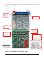
The PCB of the ELMB-DAC can be fitted in a green box in the same way as an ELMB
Motherboard does. All connectors are located at the front of the PCB.
The standard CANopen ([1]) software for the ELMB+motherboard (ELMBio version 3.5,
[3]) supports up to four ELMB-DACs, thus providing a total of 64 12-bit analog output cha nnels. Both current or voltage output is possible.
The ELMB-DAC can be used in other systems and by other controllers (non-ELMB) as
well, since it is controlled through a simple serial interface (3-wire plus a select-signal).
2 Hardware Description
Summary:
• 16 channels @ 12-bit using four 12-bit 4-channel MAX525 ICs ([4], and also see
Appendix A. MAX525) digitally daisy-chained (Two different versions of MAX525 are
available: MAX525A with 0.5 LSB 'Integral Nonlinearity', or MAX525B with 1.0 LSB
'Integral Nonlinearity').
• Controlled through a 3-wire serial interface, opto-isolated from the controller, with
HCPL-0731 type optocouplers.
• One-of- five module-select signal selectable by jumper, also opto-isolated.
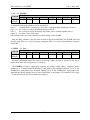
• Current output 0-20 mA, or 0-1 mA, depending on the value of one onboard resistor per
channel.
• Output accuracy depends on the precision of installed resistors, i.e. 1% or 0.1%.
• Space for optional DIL resistor packages in case voltage output is required.
• Power:
o Optocouplers: powered by the +3.3V supplied on the 'digital' connector (from the
ELMB, ca. 5 mA)
o DAC digital circuitry: powered by the +5V supplied on the 'digital' connector (from
the ELMB, ca. 5 mA)
o Current-output circuitry: powered externally via a separate connection to a powersupply VE or -with restrictions- by the +5V supplied from the 'digital' connector (from the
ELMB), selectable by jumpers.
o Current output 0-20 mA: output circuits must be powered by the separate external
powersupply VE (5 to 30V), if an ELMB is the controller of the DAC.
Voltage output: ca.(VE-2.5) Volts maximum (there is also a minimum, see below).
o Current output 0-1 mA: output circuit can be powered either from +5V (from the
ELMB) or an external powersupply.
If the ELMB is used for powering (5V), the voltage output can be ca. 2.5V maximum.
2