1
DAC-module for the ELMB
v1.0 3-May-2002
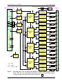
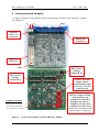
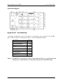
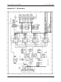
Figure 1 below shows a blockdiagram of the ELMB-DAC. Note the jumper block used to set
a module ‘address’, and the jumper selecting the power for the current output circuitry. Beware: it is always necessary to use a separate external powersupply VE for 0-20 mA current
output: an ELMB is not capable to supply enough current.
The external powersupply voltage VE can be in the range of +5V to +30V but some care
must be taken to protect the output circuit from overdissipation. The dissipation in the output
FET should be limited to ca. 200 mW (FET datasheet: 600 mW max).
So for output current I=20mA, the voltage across the FET should not exceed
200mW/20mA=10V. The dissipation D in the FET is described by the following formula:
D=I*(V E-2.2) Watts. This means that either VE<12.2V or that the external load has a voltage
drop of at least (VE-12.2) Volts or, in other words, represent a minimum load of (VE-12.2)/20
kΩ.
For example: for a 15V powersupply the output load should be at least 2.8/20 kΩ = 140 Ω.
So for supply voltages of about 12V and higher a minimum load is required, if 20 mA output
current is used. For 1 mA output current no minimum load is required.
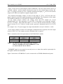
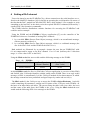
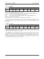
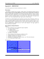
Table 1 summarizes the load requirements of the ELM B-DAC module.
Output
[mA]
0-20 mA
0-1 mA
Min. Load
[kΩ ]
(VE-12.2)/20
0
Max. Load
[kΩ ]
(VE-2.2)/20
VE-2.2
Table 1. ELMB-DAC load requirements (per channel).
When an ELMB powers the ELMB-DAC VE=5V
(i.e. max. load at 1 mA is 2.8 kΩ ).
The DOUT signal is not essential (it can only serve as a data echo) and the optocoupler for
this signal could be left uninstalled.
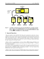
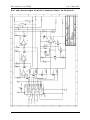
Figure 2 shows how 4 ELMB-DACs can be connected to an ELMB+Motherboard system.
3