1
NetSure™ SCU+ (Standard Control Unit Plus) User Manual UM1M521BNA (Issue AD, April 19, 2012) SPEC. NO. MODEL 1M521BNA M521B Business-Critical Continuity™, Emerson Network Power, and the Emerson Network Power logo are trademarks and service marks of Emerson Electric Co. NetSure™, NetSpan™, NetReach™, NetXtend™, and NetPerform™ are trademarks of Emerson Network Power, Energy Systems, North America, Inc. All other trademarks are the property of their respective owners. The products covered by this instruction manual are manufactured and/or sold by Emerson Network Power, Energy Systems, North America, Inc. The information contained in this document is subject to change without notice and may not be suitable for all applications. While every precaution has been taken to ensure the accuracy and completeness of this document, Emerson Network Power, Energy Systems, North America, Inc. assumes no responsibility and disclaims all liability for damages resulting from use of this information or for any errors or omissions. Refer to other local practices or building codes as applicable for the correct methods, tools, and materials to be used in performing procedures not specifically described in this document. This document is the property of Emerson Network Power, Energy Systems, North America, Inc. and contains confidential and proprietary information owned by Emerson Network Power, Energy Systems, North America, Inc. Any copying, use, or disclosure of it without the written permission of Emerson Network Power, Energy Systems, North America, Inc. is strictly prohibited. Copyright © 2012, Emerson Network Power, Energy Systems, North America, Inc. All rights reserved throughout the world. User Instructions Spec. No. 1M521BNA (Model M521B) UM1M521BNA Issue AD, April 19, 2012 TABLE OF CONTENTS Chapter 1. Introduction ..........................................................................................................1 1.1 Preface ......................................................................................................................................................... 1 1.2 Overview....................................................................................................................................................... 1 1.3 Feature Descriptions .................................................................................................................................... 1 1.3.1 Rectifier Control ................................................................................................................................ 1 1.3.2 System Component Monitoring and System Alarm Generation ....................................................... 1 1.3.3 Operating Data Acquisition and Data Logs ...................................................................................... 2 1.3.4 Battery Management ........................................................................................................................ 2 1.3.5 Intelligent Power Matching (Energy Optimization Mode) ................................................................. 5 Chapter 2. Operation ..............................................................................................................6 2.1 Local Indicators ............................................................................................................................................ 6 2.2 Passwords and Access Rights ..................................................................................................................... 7 2.3 Local Keypad Access ................................................................................................................................... 8 2.3.1 Local Menu Navigation Keys and LCD Display ................................................................................ 8 2.3.2 Local Display Menus ........................................................................................................................ 8 2.4 Web Interface Access .................................................................................................................................. 9 2.4.1 Overview ........................................................................................................................................... 9 2.4.2 WEB Interface Menus ....................................................................................................................... 9 2.4.3 Connecting the Controller Locally (via the Ethernet Port) ................................................................ 9 2.4.4 Disabling Proxy Server Settings to Enable a Connection to the Controller over an Intranet Network (if required) ....................................................................................................................... 10 2.4.5 Logging into the Controller ............................................................................................................. 11 2.5 Common Tasks Performed via the Local Keypad and/or Web Interface ................................................... 12 2.5.1 Changing the LCD Contrast ........................................................................................................... 12 2.5.2 Changing the Time Zone ................................................................................................................ 12 2.5.3 Changing the Date .......................................................................................................................... 12 2.5.4 Changing the Time ......................................................................................................................... 12 2.5.5 Viewing/Changing the Float Voltage Setting .................................................................................. 12 2.5.6 Viewing/Changing the Boost Voltage Setting ................................................................................. 12 2.5.7 Viewing Alarms ............................................................................................................................... 13 2.5.8 Programming the Audible Alarm Feature ....................................................................................... 13 2.5.9 Clearing the Alarm History Log....................................................................................................... 13 2.5.10 Blocking Alarms .............................................................................................................................. 13 2.5.11 Clearing a Rectifier Lost Alarm ....................................................................................................... 13 2.5.12 Clearing a Rectifier Communication Failure Alarm ........................................................................ 13 2.5.13 Clearing a Battery Test Fail Alarm ................................................................................................. 14 2.6 Available Alarms......................................................................................................................................... 14 Chapter 3. Local Display Menus .......................................................................................... 18 3.1 Overview..................................................................................................................................................... 18 3.2 Description of Local Display (and Web Interface) Menus Line Items ........................................................ 25 3.2.1 Settings Menu ................................................................................................................................. 25 3.2.2 ECO Mode (Energy Optimization) Menu ........................................................................................ 33 Table of Contents i This document is property of Emerson Network Power, Energy Systems, North America, Inc. and contains confidential and proprietary information owned by Emerson Network Power, Energy Systems, North America, Inc. Any copying, use, or disclosure of it without the written permission of Emerson Network Power, Energy Systems, North America, Inc. is strictly prohibited. UM1M521BNA Issue AD, April 19, 2012 3.2.3 3.2.4 User Instructions Spec. No. 1M521BNA (Model M521B) Manual Mode Menu ........................................................................................................................ 33 Quick Setting Menu ........................................................................................................................ 33 Chapter 4. Web Interface Menus ......................................................................................... 35 4.1 Overview..................................................................................................................................................... 35 4.2 Home Page ................................................................................................................................................ 35 4.3 AC Webpage .............................................................................................................................................. 36 4.4 DC Webpage .............................................................................................................................................. 37 4.5 Rectifier Webpage ...................................................................................................................................... 38 4.6 Battery Charge Webpage ........................................................................................................................... 40 4.7 Battery Test Webpage................................................................................................................................ 41 4.8 Battery Temperature Webpage .................................................................................................................. 42 4.9 ECO Mode Webpage ................................................................................................................................. 43 4.10 Communication Webpage .......................................................................................................................... 44 4.11 Active Alarm Log Webpage ........................................................................................................................ 45 4.12 History Alarm Log Webpage ...................................................................................................................... 46 4.13 Battery Discharge Webpage ...................................................................................................................... 47 4.14 System Webpage ....................................................................................................................................... 48 4.15 Up/Download Webpage ............................................................................................................................. 49 4.16 SCU+ Web Bootloader Interface Operation ............................................................................................... 51 4.17 SCU+ Serial Bootloader Interface Operation ............................................................................................. 52 Chapter 5. Accessing the Controller via a Network Management System (NMS) ........... 57 5.1 General ....................................................................................................................................................... 57 5.2 NMS Supported by SNMP Agent ............................................................................................................... 57 5.3 MIB Installation ........................................................................................................................................... 57 5.3.1 Installation....................................................................................................................................... 57 5.3.2 Contents of the Controller’s MIB..................................................................................................... 57 5.4 Accessing the Controller through an NMS ................................................................................................. 60 5.4.1 Apply Administrative Authority ........................................................................................................ 60 Chapter 6. Replacement Procedures .................................................................................. 61 6.1 SCU+ Controller Replacement ................................................................................................................... 61 Chapter 7. Specifications ..................................................................................................... 63 Revision Record ..................................................................................................................... 64 ii Table of Contents This document is property of Emerson Network Power, Energy Systems, North America, Inc. and contains confidential and proprietary information owned by Emerson Network Power, Energy Systems, North America, Inc. Any copying, use, or disclosure of it without the written permission of Emerson Network Power, Energy Systems, North America, Inc. is strictly prohibited. User Instructions Spec. No. 1M521BNA (Model M521B) UM1M521BNA Issue AD, April 19, 2012 CHAPTER 1. INTRODUCTION 1.1 Preface These instructions describe the complete functionality of the SCU+ Controller. Some functionality is dependent on hardware connected to the SCU+ Controller. Your system may not utilize all the functionality described. Refer also to the SCU+ Configuration Drawing (C-drawing) furnished with your system for a list of factory default settings. 1.2 Overview The SCU+ Controller performs the following functions. Automatic or Manual Rectifier Control System Components Monitoring and System Alarm Generation (including recording alarms in logs) Operating Data Acquisition and Data Logs Battery Management Intelligent Power Matching (Energy Optimization Mode) The SCU+ controls the system automatically via configured parameters. A User interfaces with the SCU+ Controller locally using the local keypad and LCD display or locally/remotely using the WEB Interface. The SCU+ Controller can also be accessed via SNMP (v1 and v2). 1.3 Feature Descriptions 1.3.1 Rectifier Control Rectifiers are automatically controlled by the SCU+ Controller, or a User can place the SCU+ Controller in manual mode to manually control the rectifiers. The SCU+ Controller can also be programmed to provide an Energy Optimization Mode function. Energy Optimization permits an installation to only operate rectifiers as needed to maintain the load and keep batteries in a fully charged condition. As load increases, Energy Optimization turns on additional rectifiers as needed to maintain the load. As load decreases, Energy Optimization places rectifiers in standby to conserve energy usage. Rectifiers which are always operating to maintain any load requirements are cycled through the group of rectifiers controlled by this feature to provide uniform operating times for each rectifier. 1.3.2 System Component Monitoring and System Alarm Generation The SCU+ Controller monitors the components comprising the system (such as rectifiers) and generates alarms if a fault condition occurs. The SCU+ Controller also maintains an alarm history log. The available system alarms are programmed with an Alarm Severity Level. Each Alarm Severity Level has different visual/audible alarm attributes. Available Alarm Severity Levels and their attributes are listed in Table 1. Chapter 1. Introduction 1 This document is property of Emerson Network Power, Energy Systems, North America, Inc. and contains confidential and proprietary information owned by Emerson Network Power, Energy Systems, North America, Inc. Any copying, use, or disclosure of it without the written permission of Emerson Network Power, Energy Systems, North America, Inc. is strictly prohibited. UM1M521BNA Issue AD, April 19, 2012 User Instructions Spec. No. 1M521BNA (Model M521B) Alarm Severity Level SCU+ Red Alarm Indicator SCU+ Yellow Alarm Indicator SCU+ Audible Alarm Major Alarm (MJ) ON OFF ON Minor Alarm (MN) ON OFF ON Observation Alarm (OA) OFF ON OFF No Alarm OFF OFF OFF Table 1 Alarm Severity Levels The alarm indicator turns OFF if the fault(s) that triggered the alarm clears. The audible alarm can be silenced by pressing any key on the SCU+ Controller local interface pad. The audible alarm is also silenced if the fault(s) that triggered the alarm clears. An audible alarm cutoff feature can be programmed that silences the audible alarm after a pre-set programmable time period. The audible alarm can also be disabled. The available system alarms can also be mapped to alarm relays that can be wired to external alarm circuits. 1.3.3 Operating Data Acquisition and Data Logs The SCU+ Controller acquires and analyses real time data from the system’s components such as the rectifiers and batteries. The SCU+ Controller uses this data to process alarms and also records some data in logs. The logs are viewed using the Web Interface and consist of... Alarm History Log: Records 200 most recent alarms. Battery Test Log: Up to 10 battery discharge tests can be performed and recorded per year. Note: Once maximum number of log entries reached, new entries overwrite oldest entries. 1.3.4 Battery Management The SCU+ Controller provides the following battery management functions. Battery Charge Temperature Compensation Battery Boost Charge and Battery Charge Current Limit High and Low Battery Temperature Alarms Battery Discharge Tests and Battery Test Logs Battery LVD (Low Voltage Disconnect) Battery Charge Temperature Compensation The SCU+ Controller can be programmed to automatically increase or decrease system output voltage to maintain battery float current as battery temperature decreases or increases, respectively. Battery life can be extended when an optimum charge voltage to the battery with respect to temperature is maintained. Temperature is monitored by a sensor mounted on the battery. See your power system documentation for temperature sensor information. Functional Description (See Figure 1): Battery charge temperature compensation adds a correction term, related to the temperature of the batteries, to the nominal value of the system voltage. The degree of 2 Chapter 1. Introduction This document is property of Emerson Network Power, Energy Systems, North America, Inc. and contains confidential and proprietary information owned by Emerson Network Power, Energy Systems, North America, Inc. Any copying, use, or disclosure of it without the written permission of Emerson Network Power, Energy Systems, North America, Inc. is strictly prohibited. User Instructions Spec. No. 1M521BNA (Model M521B) UM1M521BNA Issue AD, April 19, 2012 regulation (compensation coefficient), expressed in mV/°C/battery string, can be set per battery manufacturer recommendations. To protect batteries and voltage-sensitive loads, compensation is automatically limited to a maximum of two volts (48V systems) or one volt (24 volt systems) above or below the nominal output level (float setting). As shown in Figure 1, compensation clamps at the Battery Temperature Low 1 and High 1 alarm settings; temperature excursions beyond these values will not cause any further change in voltage. Compensation may also be limited by the Over Voltage 1 and Under Voltage 1 alarm settings: voltage will clamp at 0.2 volts (48V systems) or 0.1 volt (24 volt systems) from these settings. Temperature compensation is automatically disabled if communication between the Controller and all rectifiers is lost, a DC over or under voltage alarm activates, a low voltage disconnection occurs, manual mode is entered, or the system enters the boost or test modes. Compensation Coefficient setting (mV/°C) Vhigh (Limited to 0.1V [24V syst.] or 0.2V [48V syst.] below DC Over Volt 1 Alarm setting.) Vnom (= Float setting) V low (Limited to 0.1V [24V syst.] or 0.2V [48V syst.] above DC Under Volt 1 Alarm setting.) 1V Max (24V System) 2V Max (48V System) 1V Max (24V System) 2V Max (48V System) Tlower Tnom Tupper (Batt Temp Low 1 Alarm setting) (Center Temp setting) (Batt Temp High 1 Alarm setting) Figure 1 Temperature Compensated Voltage Control Battery Boost Charge and Battery Charge Current Limit The SCU+ Controller can increase system output voltage for equalizing the charge on all battery cells of a conventional flooded cell battery, or for recharging the battery following a commercial power failure. The boost charging function can be initiated cyclically (via programmable scheduling), automatically, or manually. Refer to the battery manufacturer's instructions for equalize charging recommendations. Functional Description (See Figure 2): Start of Charging: When the battery discharge current exceeds a preset value for 3 minutes or if the calculated battery capacity has decreased to a preset value (after a commercial AC failure, for example), the charging function of the SCU+ is activated. A charging signal is sent from the SCU+ to the rectifiers to increase the voltage to the battery charging level Vboost. Battery Current Limitation: After a commercial AC failure or in cases where some battery cells are permanently damaged, the current to the batteries can be quite extensive. To avoid overheating or further damages to the battery, the SCU+ limits the battery current to a preset level by limiting the charging voltage of the rectifiers. Should the battery current still exceed a higher preset value, an alarm is issued. Chapter 1. Introduction 3 This document is property of Emerson Network Power, Energy Systems, North America, Inc. and contains confidential and proprietary information owned by Emerson Network Power, Energy Systems, North America, Inc. Any copying, use, or disclosure of it without the written permission of Emerson Network Power, Energy Systems, North America, Inc. is strictly prohibited. UM1M521BNA Issue AD, April 19, 2012 User Instructions Spec. No. 1M521BNA (Model M521B) End of Charging: When the charging current drops below a preset value, a defined prolonged charging time is started before the charging is stopped and the voltage of the rectifiers return to the float charging level (Vnom). For security, there is an equalize-charging limit time that stops the charging after a preset time. Vboost Boost Vnom Mains fault Figure 2 Voltage Characteristics on Commercial AC Failure and Automatic Equalize Charging High and Low Battery Temperature Alarms The SCU+ Controller can monitor battery temperature via a temperature sensor mounted on a battery cell. Values for high battery temperature and low battery temperature alarms can then be programmed into the SCU+ Controller. Battery Discharge Test and Battery Test Logs The SCU+ Controller can perform battery discharge tests to check the condition of the battery. Three test types are available. Full-Load Time Test: (See Figure 3.) In this test, the entire system load is placed on the batteries for a preset period of time. If battery voltage and capacity remain above preset limits until the test time elapses, the batteries pass. The User can program the test-ending settings of time, voltage and capacity. Constant-Current Time Test: In this variation of the Full-Load Time Test, a constant portion of the system load is placed on the batteries for a preset period of time. Again, if battery voltage and capacity remain above preset limits until the test time elapses, the battery passes. In addition to time, voltage and capacity settings, the User can select the amount of load applied to the batteries. Short Time Test: This short-duration test monitors and compares the discharge currents of two parallel battery strings. If the difference in the two discharge currents remains below a preset level until the test time elapses, the batteries pass. The User can choose the length of the test, the alarm current and the interval between tests. (Note: This test requires two battery shunts.) In all three tests, if test requirements are met the Controller returns the system to the float charge mode. If requirements are not met, the test is interrupted, a “test fail” alarm is activated and the Controller returns the system to the float charge mode. Test results are automatically saved in a battery test log. A User can manually start a battery discharge test or program the Controller to automatically start the tests at scheduled intervals. V nom Test OK V end Test not OK Test time Time (hours) Figure 3 Battery Full-Load and Constant-Current Time Test Diagram 4 Chapter 1. Introduction This document is property of Emerson Network Power, Energy Systems, North America, Inc. and contains confidential and proprietary information owned by Emerson Network Power, Energy Systems, North America, Inc. Any copying, use, or disclosure of it without the written permission of Emerson Network Power, Energy Systems, North America, Inc. is strictly prohibited. User Instructions Spec. No. 1M521BNA (Model M521B) UM1M521BNA Issue AD, April 19, 2012 Battery LVD (Low Voltage Disconnect) To prevent serious damage to the batteries during a long commercial AC power failure, the batteries can be disconnected by voltage or time control. The batteries are reconnected automatically after a pre-determined DC voltage level is reached. The user can select whether or not restoration of AC input power is also required for reconnection to occur. Voltage-Controlled Disconnection: When the set voltage level is reached, the batteries are disconnected. Time-Controlled Disconnection: When the set time has elapsed, the batteries are disconnected. 1.3.5 Intelligent Power Matching (Energy Optimization Mode) With Energy Optimization (ECO): The controller monitors load current versus system capacity. The controller commands some rectifiers to standby in rotation. Refer to 1.3.1 Rectifier Control for further description. Chapter 1. Introduction 5 This document is property of Emerson Network Power, Energy Systems, North America, Inc. and contains confidential and proprietary information owned by Emerson Network Power, Energy Systems, North America, Inc. Any copying, use, or disclosure of it without the written permission of Emerson Network Power, Energy Systems, North America, Inc. is strictly prohibited. UM1M521BNA Issue AD, April 19, 2012 User Instructions Spec. No. 1M521BNA (Model M521B) CHAPTER 2. OPERATION 2.1 Local Indicators Location and Identification: Refer to Figure 4. Description: There are three (3) indicators located on the SCU+ Controller’s front panel. Refer to Table 2 for the function of the indicators. 10M Ethernet Port (RJ-45) Factory Use Only Major or Minor Alarm Indicator (Red) Observation Alarm Indicator (Yellow) ENT ESC Status Indicator (Green) Menu Navigation Keys Figure 4 Local Indicators and Menu Navigation Keys Locations Indicator Normal State Fault State Fault Cause Status (Green) On Off No input power to the SCU+ Controller. Observation Alarm (Yellow) Off On The system has one or more active Observation alarms. Alarm conditions are programmable. Major or Minor Alarm (Red) Off On The system has one or more active Major or Minor alarms. Alarm conditions are programmable. Table 2 Local Indicators 6 Chapter 2. Operation This document is property of Emerson Network Power, Energy Systems, North America, Inc. and contains confidential and proprietary information owned by Emerson Network Power, Energy Systems, North America, Inc. Any copying, use, or disclosure of it without the written permission of Emerson Network Power, Energy Systems, North America, Inc. is strictly prohibited. User Instructions Spec. No. 1M521BNA (Model M521B) 2.2 UM1M521BNA Issue AD, April 19, 2012 Passwords and Access Rights User passwords (for local and Web access to the SCU+ Controller) can be set via the local interface or the Web Interface. While anyone can view system status locally, a password is required to change settings. Web access always requires entering a User Name and password. The SCU+ accommodates up to three users. Each has a User Name, Password, and Access Rights. User Name: Not configurable. Refer to the following table. Password: Maximum 6 characters (0-9, a-z, A-Z, _). Once a password is entered, it remains in effect for a preset time period to allow navigating between menus without re-entering the password. Access Rights: Not configurable. Refer to the following table. Note: User Names and Passwords are case-sensitive. User Name - Local (User Name - Web) Oper1 (operator) Oper2 (Has no Web access.) Admin (admin) Default Password Access Rights: User can… 1 Operate system and adjust most system settings (cannot change ECO parameters or reset system parameters to configuration file defaults). Change Operator 1 password or reset to default. 2 Operate system and adjust most system settings including energy saving (ECO) parameters. Change Operator 1 and 2 passwords or reset to defaults. Reset system parameters to configuration file defaults. 3 Operate system and adjust all system parameters. Change all passwords or reset to defaults. Reset system parameters to configuration file defaults. Upload and download configuration files. Transfer to serial download mode. Chapter 2. Operation 7 This document is property of Emerson Network Power, Energy Systems, North America, Inc. and contains confidential and proprietary information owned by Emerson Network Power, Energy Systems, North America, Inc. Any copying, use, or disclosure of it without the written permission of Emerson Network Power, Energy Systems, North America, Inc. is strictly prohibited. UM1M521BNA Issue AD, April 19, 2012 2.3 User Instructions Spec. No. 1M521BNA (Model M521B) Local Keypad Access 2.3.1 Local Menu Navigation Keys and LCD Display Location and Identification: Refer to Figure 4. Description: There are four (4) menu navigation keys and an LCD display located on the SCU+ Controller’s front panel. Refer to Table 3 for the function of the menu navigation keys. Note: When the LCD is lit, if no button is pushed for 8 minutes, the backlight of the LCD display extinguishes and the SCU+ Controller returns to the Main Screen. Press any key to re-activate the LCD display. Key Symbol Key Name Function ESC Escape Press this key to go back to a previous menu or to cancel setting a parameter. ENT Enter Press this key to go forward to the next menu, to select a parameter to edit, or to validate a parameter setting change. Up Down Press or to scroll through the menus or to change the value of a parameter. Press any key to silence an audible alarm. Table 3 Local Menu Navigation Keys 2.3.2 Local Display Menus Refer to Chapter 3. Local Display Menus. Navigating the Menus To Select a Sub-Menu: Press and to move the cursor up and down the list of sub-menus in the menu screen (selects the sub-menu), then press ENT to enter the selected sub-menu. To Change a Parameter: Press and to move the cursor up and down the list of parameters in the menu screen (selects the parameter to change), then press ENT to change the selected parameter. The parameter field highlights. Press and to change the parameter value. Press ENT to confirm the change. Note: A valid password is required to access menus that allow changing any power system parameters. Refer to “2.2 Passwords and Access Rights”. 8 Chapter 2. Operation This document is property of Emerson Network Power, Energy Systems, North America, Inc. and contains confidential and proprietary information owned by Emerson Network Power, Energy Systems, North America, Inc. Any copying, use, or disclosure of it without the written permission of Emerson Network Power, Energy Systems, North America, Inc. is strictly prohibited. User Instructions Spec. No. 1M521BNA (Model M521B) 2.4 UM1M521BNA Issue AD, April 19, 2012 Web Interface Access Note: The SCU+ supports an Ethernet connection speed up to 10mbps. 2.4.1 Overview Via the Web Interface, a User(with proper access) can: View real-time operating information (rectifiers, AC, DC, batteries, etc.). View information recorded in logs. Send control commands. Set programmable parameters. Download and upload configuration files. Download firmware to the Controller. 2.4.2 WEB Interface Menus Refer to “Chapter 4. Web Interface Menus”. 2.4.3 Connecting the Controller Locally (via the Ethernet Port) Before connecting your computer directly to the Controller’s Ethernet Port, record your current network settings as outlined below, then change these settings to match the settings programmed into the Controller. Procedure 1) Record your computer’s network settings by launching Control Panel in your computer. Navigate through Network Connections Local Area Connection Properties Internet Protocol (TCP/IP) Properties. 2) Record whether the "Obtain an IP address automatically" or "Use the following IP address" button is selected. If "Use the following IP address" button is selected, also record the following: IP Address: Subnet Mask: Default Gateway: 3) Record your Controller’s network settings by navigating the Controller’s local display panel to Main Menu Settings Communication. 4) Record the following information: IP Address: Subnet Mask: Default Gateway: Example: IP Address: Subnet Mask: Default Gateway: 192.168.1.2 255.255.255.0 192.168.1.1 5) Change your local computer’s network settings using the information you acquired in Step 5., except that the last part of the IP address needs to be replaced with any different number. IP Address: Subnet Mask: Default Gateway: Example: IP Address: Subnet Mask: Default Gateway: 192.168.1.3 255.255.255.0 192.168.1.1 Chapter 2. Operation 9 This document is property of Emerson Network Power, Energy Systems, North America, Inc. and contains confidential and proprietary information owned by Emerson Network Power, Energy Systems, North America, Inc. Any copying, use, or disclosure of it without the written permission of Emerson Network Power, Energy Systems, North America, Inc. is strictly prohibited. UM1M521BNA Issue AD, April 19, 2012 User Instructions Spec. No. 1M521BNA (Model M521B) 6) Select OK. Note that you may have to reboot your local computer for the settings to take effect. Follow any instruction you see on the screen. 2.4.4 Disabling Proxy Server Settings to Enable a Connection to the Controller over an Intranet Network (if required) Note: This procedure needs to be performed only when the Controller is connected to an Intranet and the User’s computer is set to access the Intranet through a proxy server. Note that if the Controller is connected to the Internet and the User’s computer is connected to an Intranet, the User may not be able to disable the proxy server and access the Controller. If the Controller’s Ethernet Port is connected to your company’s Intranet Network and your computer is also connected to the Intranet Network but requires access via a proxy server, you must disable the proxy server settings to access the Controller. Follow the procedure below to disable the proxy server settings. Procedure 1) Launch “Internet Explorer”. 2) Select Internet Options from the Tools menu. The “Internet Options” window opens. In the “Internet Options” window, select the Connections tab. 3) Click on the LAN Settings... button. The following window opens. In the LAN Settings window, uncheck the Proxy Server box and click OK. 10 Chapter 2. Operation This document is property of Emerson Network Power, Energy Systems, North America, Inc. and contains confidential and proprietary information owned by Emerson Network Power, Energy Systems, North America, Inc. Any copying, use, or disclosure of it without the written permission of Emerson Network Power, Energy Systems, North America, Inc. is strictly prohibited. User Instructions Spec. No. 1M521BNA (Model M521B) UM1M521BNA Issue AD, April 19, 2012 2.4.5 Logging into the Controller Procedure 1) Internet Explorer, version 5.5 or newer, is required. It is best to view the WEB Interface at 1280 x 1024 resolution. In newer versions of Internet Explorer, you may need to turn Compatibility View On (Tools Menu / Compatibility View). 2) In Internet Explorer, enter the IP address programmed into the Controller and press ENTER. The following Login window opens. Enter a valid User Name and Password then click OK. For security, the password is not displayed on the computer’s screen while you log on. You have three attempts to enter a valid user name and password. If both are not entered correctly in three attempts, the browser is redirected to a blank page. You will then need to reenter the IP address and press ENTER to reopen the login window. Note: User names and passwords are case-sensitive. By default, there are two User Name and Password combinations. One is “admin” and “3”; the other is “operator” and “1”. 3) After entering a valid User Name and Password and clicking LOGIN, the "HOMEPAGE" window opens. Refer to Chapter 4 Web Interface Menus. Note: To prevent unauthorized personnel from accessing the power system with your Access Rights, it is recommended that you always close your browser when finished with a session. Chapter 2. Operation 11 This document is property of Emerson Network Power, Energy Systems, North America, Inc. and contains confidential and proprietary information owned by Emerson Network Power, Energy Systems, North America, Inc. Any copying, use, or disclosure of it without the written permission of Emerson Network Power, Energy Systems, North America, Inc. is strictly prohibited. UM1M521BNA Issue AD, April 19, 2012 2.5 User Instructions Spec. No. 1M521BNA (Model M521B) Common Tasks Performed via the Local Keypad and/or Web Interface Refer also to “Chapter 3. Local Display Menus” and “Chapter 4. WEB Interface Menus”. 2.5.1 Changing the LCD Contrast While in the Main Screen, simultaneously press ENT and or ENT and to change the contrast of the LCD display. Web Menu Navigation: None. 2.5.2 Changing the Time Zone Menu Navigation: Main Menu / Settings / Controller / TZone After selecting Time Zone (by pressing ENT when the cursor is in the Time Zone field), use and to select the time zone (time difference from GMT time), then press ENT. Web Menu Navigation: None. 2.5.3 Changing the Date Menu Navigation: Main Menu / Settings / Controller / Date The SCU+ displays the date in the YYYY-MM-DD format. After selecting “Date” (by pressing ENT when the cursor is in the Date field), use or to scroll through the days, months and years. When the desired year, month and day are displayed, press ENT. Note: When an arrow key is held depressed, scrolling speed will increase. To scroll quickly through days and months to reach the correct year, press and hold the required arrow key. When close to the correct year, release the key. Press and release arrow keys as required to display the correct year. Repeat process to reach the correct month and then the correct day. Web Menu Navigation: System. 2.5.4 Changing the Time Menu Navigation: Main Menu / Settings / Controller / Time The SCU+ displays the time in the HH:MM:SS format, based on a 24 hr. clock. After selecting “Time” (by pressing ENT when the cursor is in the Time field), use or to scroll through the seconds, minutes and hours. When the desired hour, minute and second are displayed, press ENT. Note: When an arrow key is held depressed, scrolling speed will increase. To scroll quickly through seconds and minutes to reach the correct hour, press and hold the required arrow key. When close to the correct hour, release the key. Press and release arrow keys as required to display the correct hour. Repeat process to reach the correct minute and then the correct second. Web Menu Navigation: System. 2.5.5 Viewing/Changing the Float Voltage Setting Menu Navigation: Main Menu / Settings / Battery / Charge / Float After selecting “Float” (by pressing ENT when the cursor is in the Float field), use or to adjust the float voltage setting as required. Press ENT. Web Menu Navigation: Battery / Battery Charge. 2.5.6 Viewing/Changing the Boost Voltage Setting Menu Navigation: Main Menu / Settings / Battery / Charge / Boost After selecting “Boost” (by pressing ENT when the cursor is in the Boost field), use or to adjust the boost voltage setting as required. Press ENT. Web Menu Navigation: Battery / Battery Charge. 12 Chapter 2. Operation This document is property of Emerson Network Power, Energy Systems, North America, Inc. and contains confidential and proprietary information owned by Emerson Network Power, Energy Systems, North America, Inc. Any copying, use, or disclosure of it without the written permission of Emerson Network Power, Energy Systems, North America, Inc. is strictly prohibited. User Instructions Spec. No. 1M521BNA (Model M521B) UM1M521BNA Issue AD, April 19, 2012 2.5.7 Viewing Alarms Menu Navigation: Main Menu / Status / Active Alarm The alarm number, name, severity, and start time are displayed. For multiple alarms, use or to scroll up or down through the alarms. Web Menu Navigation: Log / Active Alarms. 2.5.8 Programming the Audible Alarm Feature Menu Navigation: Main Menu / Settings / Alarm / Alarm Control / Alm Voice Set "Alarm Voice" to: Open: When a new alarm occurs, the audible alarm sounds. Press any key to silence the audible alarm. Close: Disables the audible alarm. 3min / 10min / 1h / 4h: When a new alarm occurs, the audible alarm sounds. The audible alarm automatically silences after the selected time period. Web Menu Navigation: None. 2.5.9 Clearing the Alarm History Log Menu Navigation: Main Menu / Settings / Alarm / Alarm Control / Clear After selecting “Clear” (by pressing ENT when the cursor is in the Clear field), use or as required to select "History" from the menu options. Press ENT to highlight the selection. Press ENT again. The alarm history log is cleared. Web Menu Navigation: None. 2.5.10 Blocking Alarms Menu Navigation: Main Menu / Settings / Alarm / Alarm Control / Block Alarm After selecting “Block Alarm” (by pressing ENT when the cursor is in the Block Alarm field), use and to select: N: Alarms are processed normally, or Y: Forces the alarm relays into the "off" state and blocks alarms from changing the relay state. Press ENT. Web Menu Navigation: None. 2.5.11 Clearing a Rectifier Lost Alarm Menu Navigation: Main Menu / Settings / Alarm / Alarm Control / Clear After selecting “Clear” (by pressing ENT when the cursor is in the Clear field), use or as required to select "Rect Lost" from the menu options. Press ENT to highlight the selection. Press ENT again. The alarm is cleared. Web Menu Navigation: None. 2.5.12 Clearing a Rectifier Communication Failure Alarm Menu Navigation: Main Menu / Settings / Alarm / Alarm Control / Clear After selecting “Clear” (by pressing ENT when the cursor is in the Clear field), use or as required to select "Rect Commb" from the menu options. Press ENT to highlight the selection. Press ENT again. The alarm is cleared. Web Menu Navigation: None. Chapter 2. Operation 13 This document is property of Emerson Network Power, Energy Systems, North America, Inc. and contains confidential and proprietary information owned by Emerson Network Power, Energy Systems, North America, Inc. Any copying, use, or disclosure of it without the written permission of Emerson Network Power, Energy Systems, North America, Inc. is strictly prohibited. UM1M521BNA Issue AD, April 19, 2012 User Instructions Spec. No. 1M521BNA (Model M521B) 2.5.13 Clearing a Battery Test Fail Alarm Menu Navigation: Main Menu / Settings / Alarm / Alarm Control / Clear After selecting “Clear” (by pressing ENT when the cursor is in the Clear field), use or as required to select "TestFail” or “Short Test” from the menu options. Press ENT to highlight the selection. Press ENT again. The alarm is cleared. Web Menu Navigation: None. 2.6 Available Alarms Table 4 lists the alarms that you can scroll through in the SETTINGS / ALARM / ALARM LEVEL menu. These are also the possible alarms that display in the Active Alarm sub-menu. Table 4 also provides guidelines for alarm correction. Note: These instructions describe the complete functionality of the SCU+. Some functionality is dependent on hardware connected to the SCU+. Some alarms listed may not display in your system or may be named differently. Refer to the SCU+ Configuration Drawing (C-drawing) furnished with your system. Alarm Name Alarm Description Action to Correct Alarm Block Alarm relays are forced in the "off" state and alarms are blocked from changing the relay state. Verify why Controller setting was changed before changing back. SPD Fault This alarm is issued if the SCU+ Controller is replaced with an ACU+ Controller and the system does not support the ACU+ Controller. Digital 1 Alarm User programmable Digital Input 1 is active. Digital 2 Alarm User programmable Digital Input 2 is active. Digital 3 Alarm User programmable Digital Input 3 is active. Digital 4 Alarm User programmable Digital Input 4 is active. Load Fuse Brkr Open distribution (load) fuse(s) or circuit breaker(s). Ext Bat Brkr Open battery fuse(s) or circuit breaker(s). Load Fuse Brkr Open distribution (load) fuse(s) or circuit breaker(s). DI 4 EX Alarm User programmable Digital Input 4 on the separate IB2 board is active. DI 5 EX Alarm User programmable Digital Input 5 on the separate IB2 board is active. DI 6 EX Alarm User programmable Digital Input 6 on the separate IB2 board is active. DI 7 EX Alarm User programmable Digital Input 7 on the separate IB2 board is active. 14 -- Check why alarm is active. Find and eliminate the cause before replacing fuse or turning on breaker. Check for overload or short circuit. If the fuse was removed or circuit breaker turned off manually, check with the person that removed/turned off device before reinserting it. Check why alarm is active. Chapter 2. Operation This document is property of Emerson Network Power, Energy Systems, North America, Inc. and contains confidential and proprietary information owned by Emerson Network Power, Energy Systems, North America, Inc. Any copying, use, or disclosure of it without the written permission of Emerson Network Power, Energy Systems, North America, Inc. is strictly prohibited. User Instructions Spec. No. 1M521BNA (Model M521B) UM1M521BNA Issue AD, April 19, 2012 Alarm Name Alarm Description Action to Correct ESTOP System in emergency stop mode. Check to see why the system was placed in this mode. LFuse Alarm Any Load Breaker/Fuse has operated open. BFuse Alarm Any Battery Breaker has operated open. LVD1CtrlFail LVD1 control circuit has failed. LVD2CtrlFail LVD2 control circuit has failed. Check the contactor functions. Replace the contactor. SelfDetect Fail Controller self detection test fails. Replace the Controller. Manual Mode Controller is in manual mode of operation. -- Boost Charge Rectifiers are operating in the boost charge mode. -- Batt Test A battery discharge test is in progress. -- Batt Discharge The batteries are discharging. Curr Imbalance Rectifiers are not sharing load current proportionately. DC Volt Fail Bus voltage is lower than a predetermined value. ShortTest Fail Batteries failed the short battery discharge test. (Parallel strings are not discharging equally.) Check the batteries. Batt Test Fail Batteries failed a Full-Load Current or Constant-Current battery discharge test. Check the batteries. LVD1 Low Voltage Disconnect contactor 1 is open. -- LVD2 Low Voltage Disconnect contactor 2 is open. -- Mains Failure The AC input of all rectifiers is lower than the AC Under Volt alarm setpoint. Check why no AC input power available. Rect Overload Rectifier output current has exceeded the Rectifier Over Current alarm setpoint. Rectifier overload. The load is higher than rectifier capacity. If the batteries are being recharged, the alarm will cease by itself when the battery voltage has increased to the charging level. If the system load is higher than the rectifier capacity, the batteries will discharge. If this is the cause, install additional rectifiers. If one or more of the rectifiers are defective, replace the faulty rectifiers. Rect Lost The controller has detected a reduction in the number of running rectifiers (RFA). Reset the Rectifier Lost alarm. Replace defective rectifier. MultiRect Alarm More than one rectifier has failed. Check input voltage to rectifiers. Replace rectifiers. Chapter 2. Operation Find and eliminate the cause before replacing fuse or turning on breaker. Check for overload or short circuit. If the fuse was removed or circuit breaker turned off manually, check with the person that removed/turned off device before reinserting it. -Refer to Rectifier User Manual for troubleshooting information. 15 This document is property of Emerson Network Power, Energy Systems, North America, Inc. and contains confidential and proprietary information owned by Emerson Network Power, Energy Systems, North America, Inc. Any copying, use, or disclosure of it without the written permission of Emerson Network Power, Energy Systems, North America, Inc. is strictly prohibited. UM1M521BNA Issue AD, April 19, 2012 User Instructions Spec. No. 1M521BNA (Model M521B) Alarm Name Alarm Description Action to Correct Rect Comm Fail Rectifier(s) unable to communicate with SCU+. Check communications cables. Reset the Communication Fail alarm. Replace the rectifier. Rect AC Fail No AC input power to a rectifier. Check why no AC input power available. Rect TempHigh High temperature protection active within at least one rectifier. Check why temperature is high. Rect Fail Serious load sharing alarm (the output current of the rectifier is lower than 1A AND the average load is greater than 10% of the total rectifier capacity). Refer to Rectifier User Manual for troubleshooting information. Rect Protect Protection circuit active within at least one rectifier due to AC input outside the allowed operating range. (See Rectifier User Manual for range.) Refer to Rectifier User Manual for troubleshooting information. Rect FanFail Fan failure within at least one rectifier. Replace fan. Refer to Rectifier User Manual for procedure. Rect Derated The output power is derated because of AC or temperature on at least one rectifier. Rect LoadShare The rectifier output current is more than 16% higher/lower than the average value for all rectifiers and the average rectifier load is greater than 20% of its capacity. Rect HVSD Rectifier High Voltage Shutdown circuit activated. SM Comm Fail Communication between Controller and SMDU has failed. Refer to Rectifier User Manual for troubleshooting information. Check communications cables. Replace the SMDU. Find and eliminate the cause before replacing fuse or turning on breaker. Check for overload or short circuit. If the fuse was removed or circuit breaker turned off manually, check with the person that removed/turned off device before reinserting it. SM LFuse Alarm Load fuse alarm detected by SM DU. SM BFuse Alarm Battery fuse alarm detected by SM DU. SM1LVD1CtrlFail SMDU1 LVD1 control circuit has failed. SM1LVD2CtrlFail SMDU1 LVD2 control circuit has failed. SM1 LVD1 LVD1 contactor is in disconnect mode. -- SM1 LVD2 LVD2 contactor is in disconnect mode. -- SM2LVD1CtrlFail SMDU2 LVD1 control circuit has failed. SM2LVD2CtrlFail SMDU2 LVD2 control circuit has failed. SM2 LVD1 LVD1 contactor is in disconnect mode. -- SM2 LVD2 LVD2 contactor is in disconnect mode. -- SM Detect Fail SMDU self-detection error. Replace SMDU. System output voltage is below DC Undervolt 1 alarm setpoint. Check to see why system voltage is low. If there is a mains failure, check if some load could be switched off in order to prolong the operating time of the plant. If the system load is too high related to DC Under Volt 1 16 Check contactor function. Replace the contactor. Check contactor function. Replace the contactor. Chapter 2. Operation This document is property of Emerson Network Power, Energy Systems, North America, Inc. and contains confidential and proprietary information owned by Emerson Network Power, Energy Systems, North America, Inc. Any copying, use, or disclosure of it without the written permission of Emerson Network Power, Energy Systems, North America, Inc. is strictly prohibited. User Instructions Spec. No. 1M521BNA (Model M521B) Alarm Name UM1M521BNA Issue AD, April 19, 2012 Alarm Description Action to Correct DC Under Volt 2 System output voltage is below DC Undervolt 2 alarm setpoint. rectifier capacity, install additional rectifiers. If the batteries are being recharged, the alarm will cease automatically when battery voltage has increased to the charging level. DC Over Volt 1 System output voltage is above DC Overvolt 1 alarm setpoint. DC Over Volt 2 System output voltage is above DC Overvolt 2 alarm setpoint. Temp[#] Low1 Temperature of probe connected to SCU+ is below Temperature Low 1 alarm setpoint. Temp[#] High1 Temperature of probe connected to SCU+ is above Temperature High 1 alarm setpoint. Temp[#] High2 Temperature of probe connected to SCU+ is above Temperature High 2 alarm setpoint. Temp[#]-EX Low1 Temperature of probe connected to IB2 board is below Temperature Low 1 alarm setpoint. Temp[#]-EX High1 Temperature of probe connected to IB2 board is above Temperature High 1 alarm setpoint. Temp[#]-EX High2 Temperature of probe connected to IB2 board is above Temperature High 2 alarm setpoint. Batt [#] Over Chg AC PH- [#] Failure The charging current exceeds the Battery Over Charge alarm setpoint. AC input phase failure. Check to see why system voltage is high. Check the alarm setting. Check why temperature is low. Check why temperature is high. Check why temperature is low. Check why temperature is high. -Check why no AC phase voltage. AC Low AC input voltage is below AC Undervolt alarm setpoint. Check why voltage is low. AC High AC input voltage is above AC Overvolt alarm setpoint. Check why voltage is high. SM DC UnderV SMDU detects a system DC under voltage condition. Check to see why system voltage is low. SM DC OverVolt SMDU detects a DC over voltage condition. Check to see why system voltage is high. SM Batt DisChg SMDU detects batteries are discharging. -- SM Batt OverChg The charging current exceeds the Battery Over Charge alarm setpoint. -- Power system is operating in the ECO mode (Energy Optimization). # - Alarm with numbers associated to them. System ECO -- Table 4 Available Alarms Chapter 2. Operation 17 This document is property of Emerson Network Power, Energy Systems, North America, Inc. and contains confidential and proprietary information owned by Emerson Network Power, Energy Systems, North America, Inc. Any copying, use, or disclosure of it without the written permission of Emerson Network Power, Energy Systems, North America, Inc. is strictly prohibited. UM1M521BNA Issue AD, April 19, 2012 User Instructions Spec. No. 1M521BNA (Model M521B) CHAPTER 3. LOCAL DISPLAY MENUS 3.1 Overview This section provides descriptions of the Local Display Menus. Refer also to 2.3 Local Keypad Access in Chapter 2 Operation. For Web interface, refer to Chapter 4 Web Interface Menus. Figure 5 provides flow diagrams of the menus accessed via the SCU+ Controller local display and keypad. Note: These instructions describe the complete functionality of the SCU+. Some functionality is dependent on hardware connected to the SCU+. Some menu items shown may not be present in the SCU+ used in your system. 18 Chapter 3. Local Display Menus This document is property of Emerson Network Power, Energy Systems, North America, Inc. and contains confidential and proprietary information owned by Emerson Network Power, Energy Systems, North America, Inc. Any copying, use, or disclosure of it without the written permission of Emerson Network Power, Energy Systems, North America, Inc. is strictly prohibited. User Instructions Spec. No. 1M521BNA (Model M521B) UM1M521BNA Issue AD, April 19, 2012 Date and time are alternately displayed. To Change LCD Contrast: While in the Main Screen, press ENT and , or ENT and at the same time. Local Access Passwords Up to 6 characters (0-9, A-Z, a-z) Figure 5 (cont’d on next page) Local Menu Flow Diagrams Chapter 3. Local Display Menus 19 This document is property of Emerson Network Power, Energy Systems, North America, Inc. and contains confidential and proprietary information owned by Emerson Network Power, Energy Systems, North America, Inc. Any copying, use, or disclosure of it without the written permission of Emerson Network Power, Energy Systems, North America, Inc. is strictly prohibited. UM1M521BNA Issue AD, April 19, 2012 User Instructions Spec. No. 1M521BNA (Model M521B) Figure 5 (cont’d from previous page, cont’d on next page) Local Menu Flow Diagrams 20 Chapter 3. Local Display Menus This document is property of Emerson Network Power, Energy Systems, North America, Inc. and contains confidential and proprietary information owned by Emerson Network Power, Energy Systems, North America, Inc. Any copying, use, or disclosure of it without the written permission of Emerson Network Power, Energy Systems, North America, Inc. is strictly prohibited. User Instructions Spec. No. 1M521BNA (Model M521B) UM1M521BNA Issue AD, April 19, 2012 (Enbl / Dsbl) (1-30) (57-59)* (48-58) (Y / N) (8-128) (0-10) (Y / N) (1-50) (0-500) (0-500) (0-500) (Y / N) (1-PH / 3-PH) (Enbl / Dsbl) (Enbl / Dsbl) (Volt / Time) (40-60)** (36-60)** (3-999) (3-999) (40-60) (40-60) (40-60) (40-60) (Y / N) (Y / N) (20-60) (20-60) (40-60)*** (40-60) (40-60) (40-60)† (10-100)‡ (10-100) (-40-10) (Y / N) (50-5000) (1-150) Notes: * Lower limit of “HVSD” range is restricted to “Boost” setting in “Settings / Battery / Charge” submenu. ** Upper limits of “LVD1 Volt” and “LVD2 Volt” ranges are restricted to “Under V2” setting in “Settings / DC” submenu. *** Lower limit of “Over Volt2” range is restricted to “Over Volt1” setting. † Upper limit of ”Under V2” range is restricted to “Under V1” setting. ‡ Lower limit of “Amb High2” range is restricted to “Amb High1” setting. (Y / N) (Y / N) (Y / N) (Y / N) (1-9999) (Y / N) Figure 5 (cont’d from previous page, cont’d on next page) Local Menu Flow Diagrams Chapter 3. Local Display Menus 21 This document is property of Emerson Network Power, Energy Systems, North America, Inc. and contains confidential and proprietary information owned by Emerson Network Power, Energy Systems, North America, Inc. Any copying, use, or disclosure of it without the written permission of Emerson Network Power, Energy Systems, North America, Inc. is strictly prohibited. UM1M521BNA Issue AD, April 19, 2012 User Instructions Spec. No. 1M521BNA (Model M521B) (Open / Close / 3min / 10min / 1h / 4h) (Y / N) (History / Rect Commb / ECOFail / Maintain / ShortTest / TestFail / Rect Lost) (High / Low) (High / Low) Figure 5 (cont’d from previous page, cont’d on next page) Local Menu Flow Diagrams 22 Chapter 3. Local Display Menus This document is property of Emerson Network Power, Energy Systems, North America, Inc. and contains confidential and proprietary information owned by Emerson Network Power, Energy Systems, North America, Inc. Any copying, use, or disclosure of it without the written permission of Emerson Network Power, Energy Systems, North America, Inc. is strictly prohibited. User Instructions Spec. No. 1M521BNA (Model M521B) UM1M521BNA Issue AD, April 19, 2012 (Auto / Manual) (0-6) (0-10) (20-5000) (Y / N) (Y / N) (1-5000) (1-500) (42.0-58.0) (N / Volt / LVD) (N / Volt / LVD) (Enbl / Dsbl) ( ) (0-0.99) ( (0-1440) ) (Enbl / Dsbl) (2-8760) (30-2880) (60-2880) (Enbl / Dsbl) (Enbl / Dsbl) (1-100) (24-8760) ( ) (Enbl / Dsbl) (1-9999) (Enbl / Dsbl) (10--40) (0-500) (10-100)* (10-100) (-40-100)** (T1-EX / T2-EX / Temp1 / Temp2) Notes: * Lower limit of “Batt T H2” range is restricted to “Batt T H1” setting. ** Upper limit of “Batt T L1” range is restricted to “Batt T H1” setting. *** Lower limit of “Boost” range is restricted to “Float” setting. Figure 5 (cont’d from previous page, cont’d on next page) Local Menu Flow Diagrams Chapter 3. Local Display Menus 23 This document is property of Emerson Network Power, Energy Systems, North America, Inc. and contains confidential and proprietary information owned by Emerson Network Power, Energy Systems, North America, Inc. Any copying, use, or disclosure of it without the written permission of Emerson Network Power, Energy Systems, North America, Inc. is strictly prohibited. UM1M521BNA Issue AD, April 19, 2012 User Instructions Spec. No. 1M521BNA (Model M521B) (Enbl/Dsbl) (1-8760) (30-90) (1-30) (0.01-0.50) (0.1-0.9) (1-9999) (Auto/Manual) (Float/Boost/Test) (Reconn/Disconn) (Reconn/Disconn) (Reconn/Disconn) (Reconn/Disconn) (42.0 - 58.0) (10-121) (Y/N) (On/Off) (On/Off) (20-5000) (Y/N) (Y/N) (1-5000) (1-500) (Y/N) (1-5000) (1-500) Figure 5 (cont’d from previous page, cont’d on next page) Local Menu Flow Diagrams 24 Chapter 3. Local Display Menus This document is property of Emerson Network Power, Energy Systems, North America, Inc. and contains confidential and proprietary information owned by Emerson Network Power, Energy Systems, North America, Inc. Any copying, use, or disclosure of it without the written permission of Emerson Network Power, Energy Systems, North America, Inc. is strictly prohibited. User Instructions Spec. No. 1M521BNA (Model M521B) 3.2 UM1M521BNA Issue AD, April 19, 2012 Description of Local Display (and Web Interface) Menus Line Items The following are descriptions of the editable parameters presented in the local display menus. Parameter descriptions can also be used for the WEB Interface menus. Note that the names in the WEB Interface menus may be longer since the WEB Interface allows more characters to be displayed then the local (LCD) display. 3.2.1 Settings Menu Alarm Alarm Level Menu Menu Navigation: Main Menu / Settings / Alarm / Alarm Level “Alarm Level” Parameter Settings: Use the menus to assign an Alarm Severity Level (none, observation, minor, major) to each possible alarm. Note: The severity levels of the “temperature sensor disconnected” and “temperature sensor failure” alarms and the corresponding relay output cannot be set through the LCD. The severity levels of these two alarms and the corresponding relay are the same as those of the high temperature alarm setting. Note: If an analog alarm has two levels of alarm thresholds and if these two thresholds are set to the same value, then the second level will be cancelled and the first level of the alarm will be displayed in the LCD. For example, with the “high temperature 1” and “high temperature 2” alarm thresholds both set to 40° C, if the temperature exceeds 40° C only a “high temperature 1” alarm will be issued. Alarm Control Menu Menu Navigation: Main Menu / Settings / Alarm / Alarm Control “Alarm Control” Parameter Settings: AlmVoice: Programs the audible alarm feature. Close: Disables the audible alarm Open: When a new alarm occurs, the audible alarm sounds. Press any key to silence the audible alarm. 3min / 10min / 1h / 4h: When a new alarm occurs, the audible alarm sounds. The audible alarm automatically silences after the selected time period. Block Alarm: Blocks or allows operation of all external alarm relays. N: Alarms are processed normally Y: Forces the alarm relays into the “off” state and blocks alarms from changing the relay state. Clear: Clears the selected alarm function. History: Clears the alarm history log. Rect Commb: Clears a “Rectifier Communication Lost” alarm. ECOFail: Clears an “ECO Fail” alarm. Maintain: Clears a “Maintenance” alarm. ShortTest: Clears the alarm generated when batteries fail a “Short Test”. TestFail: Clears the alarm generated when batteries fail a “Full-Load Time Discharge test or Constant-Current Time Discharge test. Rect Lost: Clears a “Rectifier Lost” alarm. Chapter 3. Local Display Menus 25 This document is property of Emerson Network Power, Energy Systems, North America, Inc. and contains confidential and proprietary information owned by Emerson Network Power, Energy Systems, North America, Inc. Any copying, use, or disclosure of it without the written permission of Emerson Network Power, Energy Systems, North America, Inc. is strictly prohibited. UM1M521BNA Issue AD, April 19, 2012 User Instructions Spec. No. 1M521BNA (Model M521B) DI (Digital Input) Settings Menu Menu Navigation: Main Menu / Settings / Alarm / DI Settings “DI Settings” Parameter Settings: Use the menus to configure alarm activation for each digital input. High: Alarm is activated when the digital input signal as applied. Low: Alarm is activated when the digital input signal as removed. Note: DI No.1 through DI No.2 refers to the digital inputs on the SCU+. DI No.1-EX through DI No.8-EX refers to the digital inputs on the separate IB2 customer interface board. Rectifier Rectifier Menu Menu Navigation: Main Menu / Settings / Rectifier “Rectifier” Parameter Settings: Position: Enables or Disables the rectifier positioning setting. R-Posi: Indicates a rectifier position in a shelf or system. Upon initial power system startup, the rectifiers are automatically identified according to their serial numbers, with the lowest serial number being rectifier number 1, next lowest being number 2 and so on. Slots in the power system are typically numbered from left to right and top to bottom. Using “R-Posi: 1-3” as an example, the “1” indicates that the rectifier has the lowest serial number in the system; “3” is the slot number. Note: If “Settings / AC / AC Input” is set as “No” and “Settings / AC / AC PH” as “3-PH”, the Position 1,2,3,4,5…will be assigned to phase A, B,C,A,B…accordingly. HVSD: Sets the High Voltage Shutdown point for all rectifiers. Default V: Sets rectifier default output voltage. This is the setting to which the rectifiers will revert should the Controller fail or be removed from the system, or if communication between the controller and rectifiers is lost. Walk-in On: Selects whether the walk-in feature of all rectifiers is enabled (Y) or not (N). Walk-in T: Sets the time, in seconds, required for rectifier output current to go from zero to full load at start-up. This feature (also called soft-start, ramp-up or rate of rise) is used to smooth the start-up current of the rectifiers in order to reduce inrush current on the AC supply. Interval T: Sets the sequencing delay, in seconds, for the rectifiers in the system to start supplying current after AC input power is applied to the system. This delay is applied to each rectifier in the system according to their numbering sequence. For example, if 5 seconds is selected, the first rectifier will start after 5 seconds, the second rectifier will start after 10 seconds, the third rectifier will start after 15 seconds, and so on. This feature (also called start-up delay) is used to stagger the start-up of the rectifiers in order to reduce inrush current on the AC supply. AC OverV On: Selects whether the AC Over Voltage feature is enabled (Y) or not (N). This feature allows the rectifiers to operate above their internal AC input overvoltage threshold. (See Rectifier User Manual for threshold value.) ACCurrLim: Sets rectifier input current limit value during startup process. 26 Chapter 3. Local Display Menus This document is property of Emerson Network Power, Energy Systems, North America, Inc. and contains confidential and proprietary information owned by Emerson Network Power, Energy Systems, North America, Inc. Any copying, use, or disclosure of it without the written permission of Emerson Network Power, Energy Systems, North America, Inc. is strictly prohibited. User Instructions Spec. No. 1M521BNA (Model M521B) UM1M521BNA Issue AD, April 19, 2012 Battery Basic Menu Menu Navigation: Main Menu / Settings / Battery / Basic “Basic” Parameter Settings: Sys Mode: Selects automatic or manual mode of system operation. BattFuse: Should be set to the number of battery fuses in the system. Batt Type: Not used. Setting should always be “0”. Capacity: Should be set to the capacity of the battery connected to the system. Batt Shunt1: Should be set to “Y” if system has a battery shunt and “N” if system has no battery shunt. Batt Shunt2: Should be set to “Y” if system has a second battery shunt and “N” if system does not have a second battery shunt. Shunt Coeff: The following battery shunt parameters can be set. Current: Should be set to the current rating (capacity) of the battery shunt(s). Volt: Should be set to the (full-load) voltage output of the battery shunt(s). High-T V: Sets system output voltage level in the event of high battery temperature. (“High-T 1” or “High-T 2” must be set to “Volt”.) High-T 1: Selects from the following actions if battery temperature increases to the “Batt T H1” setpoint: LVD: LVD contactor opens Volt: Output voltage is reduced N: No action High-T 2: Selects from the following actions if battery temperature increases to the “Batt T H2” setpoint: LVD: LVD contactor opens Volt: Output voltage is reduced N: No action Charge Menu Menu Navigation: Main Menu / Settings / Battery / Charge “Charge” Parameter Settings: Float: Sets the float charge voltage. Boost: Sets the boost charge voltage. Limit: Sets the battery charging current limit value. The displayed value is relative to the nominal capacity of the battery. For example, a value of 0.150C10 means that the charging current is limited to 15% of the battery’s nominal capacity. Over: Sets the Battery Over Charge alarm value. The displayed value is relative to the nominal capacity of the battery. For example, a value of 0.300C10 means that if the charging current reaches 30% of the battery’s nominal capacity, the alarm will be extended. AutoBoost: The following parameters for starting an Automatic Boost charge cycle can be set. Enable or Disable: Enables or disables the Automatic Boost Charge feature. Chapter 3. Local Display Menus 27 This document is property of Emerson Network Power, Energy Systems, North America, Inc. and contains confidential and proprietary information owned by Emerson Network Power, Energy Systems, North America, Inc. Any copying, use, or disclosure of it without the written permission of Emerson Network Power, Energy Systems, North America, Inc. is strictly prohibited. UM1M521BNA Issue AD, April 19, 2012 User Instructions Spec. No. 1M521BNA (Model M521B) Note: If the power system has been automatically placed in Boost mode, disabling AutoBoost will not return the system to the Float mode until the current Boost cycle is completed. To return immediately to Float mode, navigate as follows: Main Menu / Manual / Start, and select Float. Curr: The system is transferred to Boost Charge mode if battery charging current increases to this setting (Auto Boost must be enabled). For example, a value of 0.060C10 means that an Automatic Boost is started if the battery charge current is greater than 6% of the battery’s nominal capacity. Cap: The system is transferred to Boost Charge mode if remaining battery capacity decreases to this setting (Auto Boost must be enabled). Const Boost: The following parameters for ending an Automatic Boost charge cycle can be set. Curr: When in Boost Charge mode and the battery charge current decreases below this setting for the time period selected in “Time” (below), the system is transferred to Float Charge mode. For example, a value of 0.010C10 means that when the charging current is less than 1% of the battery’s nominal capacity, the system returns to the Float mode after the “Time” period has elapsed. Time: See “Curr” above. CycBoost: Enable or Disable: Enables or disables cyclic (scheduled) Boost charging. Period: Sets the interval, in hours, between Boost cycles. Time: Sets the duration, in minutes, of each Boost cycle. BoostLimitTime: Sets the boost charging time limit. This is the maximum duration, in minutes, that an Auto Boost cycle will last regardless of any other settings. Test Menu Menu Navigation: Main Menu / Settings / Battery / Test “Battery Discharge Test” Parameter Settings: End Test: During Full-Load Current and Constant-Current battery discharge tests, the output voltage of the rectifiers is reduced so that the batteries supply all or partial power, respectively, to the system load. The test is interrupted when one of the following conditions is reached. Volt: Sets the “end of test” voltage level for each test (battery fails test). Time: Sets the maximum duration, in minutes, for each test (battery passes test). Cap: Sets the value of the remaining battery capacity at which a test will be interrupted (battery fails test). The displayed value is relative to the nominal capacity of the battery. For example, a value of 0.700C10 means that when the discharging current reaches 70% of the battery’s nominal capacity, the battery test is interrupted. Cyc Test: Enables or disables cyclic (scheduled) Full-Load Current or Constant-Current tests. To view or modify scheduled test dates and times, see Battery Cyclic Test Time Parameters in the following section. Short Test: A short test is a short duration battery discharge test used to verify that parallel strings of batteries are discharging equally. If the discharge current difference between the two battery strings exceeds a preset adjustable level (default is 10A) within a preset time limit, a “Short Test Fail” alarm is generated. (Note: This test requires two battery shunts.) The following parameters can be set: Enbl/Dsbl: Selects whether the Short Battery Discharge Test function is enabled or disabled. If enabled, the test will automatically repeat at preset intervals. 28 Chapter 3. Local Display Menus This document is property of Emerson Network Power, Energy Systems, North America, Inc. and contains confidential and proprietary information owned by Emerson Network Power, Energy Systems, North America, Inc. Any copying, use, or disclosure of it without the written permission of Emerson Network Power, Energy Systems, North America, Inc. is strictly prohibited. User Instructions Spec. No. 1M521BNA (Model M521B) UM1M521BNA Issue AD, April 19, 2012 Alarm: Sets the discharge current difference between two battery strings at which the “Short Test Fail” alarm will be extended. Period: Sets the interval, in hours, between short battery discharge tests. Time: Sets the duration, in minutes, of each short battery discharge test. ConCurr Test: The Constant Current test is a variation of the Full-Load Current test. In the Constant-Current test, the Controller automatically adjusts the rectifiers to maintain the battery discharge current at a constant preset value. In addition to the settings listed under “End Test”, the following parameters can be set: Enbl/Dsbl: Selects whether the Constant-Current battery test function is enabled or disabled. If the Constant-Current test is disabled, the Full-Load Current test is enabled by default. Current: Sets the value of the constant load applied to the battery. Cyc (Cyclic) Test Time Menu Menu Navigation: Main Menu / Settings / Battery / Cyc Test Time “Battery Cyclic Test Time” Parameter Settings: 00-00 00:00: Setting for when a scheduled Battery Discharge Test occurs. Events are displayed in the MM-DD HH:MM format (the field for the minutes is not adjustable). Note that there can be up to 12 scheduled battery discharge tests per year. The date and time of any scheduled test can be modified as follows: 1) After selecting “Cyc Test Time” (by pressing ENT when the cursor is in the Cyc Test Time field), use or to move to the desired entry in the list. 2) Press ENT to highlight the entry. Use or to scroll through the hours, the days and the months. When the desired month, day and hour are displayed, press ENT. Note: When an arrow key is held depressed, scrolling speed will increase. To scroll quickly through hours and days to reach the correct month, press and hold the required arrow key. When close to the correct month, release the key. Press and release arrow keys as required to display the correct month. Repeat process to reach the correct day and then the correct hour. Temp Comp (Temperature Compensation) Menu Menu Navigation: Main Menu / Settings / Battery / Temp Comp “Battery Temperature Compensation” Parameter Settings: Note: Setting any probe to “battery” or “ambient” without a probe connected will cause a “T# No Probe” alarm. Note: “Temp 1” and “Temp 2” refer to the probe inputs on the SCU+. “Temp 1-EX” and “Temp 2-EX” refer to the probe inputs on the separate IB2 customer interface board. Temp 1: Selects whether a temperature probe connected to probe position 1 on the SCU+ is used for battery or ambient temperature measurements, or not used. Temp 2: Selects whether a temperature probe connected to probe position 2 on the SCU+ is used for battery or ambient temperature measurements, or not used. Temp 1-EX: Selects whether a temperature probe connected to probe position 1 on the separate IB2 customer interface board is used for battery or ambient temperature measurements, or not used. Temp 2-EX: Selects whether a temperature probe connected to probe position 2 on the separate IB2 customer interface board is used for battery or ambient temperature measurements, or not used. Chapter 3. Local Display Menus 29 This document is property of Emerson Network Power, Energy Systems, North America, Inc. and contains confidential and proprietary information owned by Emerson Network Power, Energy Systems, North America, Inc. Any copying, use, or disclosure of it without the written permission of Emerson Network Power, Energy Systems, North America, Inc. is strictly prohibited. UM1M521BNA Issue AD, April 19, 2012 User Instructions Spec. No. 1M521BNA (Model M521B) TempComp: Selects whether temperature compensation is enabled or disabled. Center Temp: Sets the temperature, in °C, at which the system operates at normal voltage levels (float setting). Coeff: Sets the temperature compensation slope, or rate of change per °C above or below the normal operation level selected in the second line. This value is expressed in millivolt per °C per string (mV/°C/str). For example, for a rate of change of 72 mV/°C/str in a 24-cell, 48 V nominal, battery string, the rate of change is 3 mV per cell. Batt T H2: Sets the temperature at which the “Temp[#] High2” or “Temp[#]-EX High2” alarm activates. Batt T H1: Sets the temperature at which the “Temp[#] High1” or “Temp[#]-EX High1” alarm activates. Note: When temperature compensation is enabled, if the “Temp High 1” alarm activates, the temperature compensation function will remain enabled, but output voltage will not decrease below the voltage present at the alarm setpoint regardless of temperature. Batt T L1: Sets the temperature at which the “Temp[#] Low1” or “Temp[#]-EX Low1” alarm activates. Note: When temperature compensation is enabled, if the “Temp Low 1” alarm activates, the temperature compensation function will remain enabled, but output voltage will not increase above the voltage present at the alarm setpoint regardless of temperature. Temp Sel: Selects which temperature probe is used for temperature compensation. LVD (Low Voltage Disconnect) LVD Menu Menu Navigation: Main Menu / Settings / LVD “Low Voltage Disconnect” Parameter Settings: LVD1: Enables or disables LVD1. LVD2: Enables or disables LVD2 LVDMode: Sets the LVD by time or by voltage. LVD1 Volt: Sets the voltage at which the LVD1 contactor disconnects if LVD Mode is set to “Volt”. LVD2 Volt: Sets the voltage at which the LVD2 contactor disconnects if LVD Mode is set to “Volt”. LVD1Time: Sets the time period after which the LVD1 contactor disconnects if LVD Mode is set to “Time”. LVD2Time: Sets the time after which the LVD2 contactor disconnects if LVD Mode is set to “Time”. SMDU1LVD1: Sets the voltage at which the SMDU1 LVD1 contactor disconnects. SMDU1LVD2: Sets the voltage at which the SMDU1 LVD2 contactor disconnects. SMDU2LVD1: Sets the voltage at which the SMDU2 LVD1 contactor disconnects. SMDU2LVD2: Sets the voltage at which the SMDU2 LVD2 contactor disconnects. LVD1 Back: Selects whether or not contradictory feedback from the LVD1contactor will issue an alarm. Alarm indicates a stuck contactor. LVD2 Back: Selects whether or not contradictory feedback from the LVD2 contactor will issue an alarm. Alarm indicates a stuck contactor. Reconn: Sets the voltage at which LVD contactor(s) will reconnect following a disconnect and subsequent DC voltage recovery. System AC input must be present. 30 Chapter 3. Local Display Menus This document is property of Emerson Network Power, Energy Systems, North America, Inc. and contains confidential and proprietary information owned by Emerson Network Power, Energy Systems, North America, Inc. Any copying, use, or disclosure of it without the written permission of Emerson Network Power, Energy Systems, North America, Inc. is strictly prohibited. User Instructions Spec. No. 1M521BNA (Model M521B) UM1M521BNA Issue AD, April 19, 2012 Ab. Reconn: Sets the voltage at which LVD contactor(s) will reconnect following a disconnect and subsequent DC voltage recovery. System AC input need not be present. AC AC Menu Menu Navigation: Main Menu / Settings / AC “AC” Parameter Settings: Over Volt: Sets the voltage at which the AC Over Voltage alarm activates. Under Volt: Sets the voltage at which the AC Under Voltage alarm activates. PH Fail: Sets the voltage at which the AC Phase Fail alarm activates. AC Input: When set to “Yes”, AC input is measured by the Controller (AC sampler board). When set to “No”, the AC value is sent from rectifiers to Controller. Note: The AC Input option is not presently used. Feature should always be set to “No”. AC PH: Should be set to the type of AC source that supplies the system (1-phase or 3-phase). DC DC Menu Menu Navigation: Main Menu / Settings / DC “DC” Parameter Settings: Over Volt2: Sets the voltage at which the Over Volt2 alarm activates. Over Volt1: Sets the voltage at which the Over Volt1 alarm activates. Under V1: Sets the voltage at which the Under Volt1 alarm activates. Under V2: Sets the voltage at which the Under Volt2 alarm activates. Amb High2: Sets the temperature at which the Amb High2 alarm activates. Amb High1: Sets the temperature at which the Amb High1 alarm activates. Amb Low: Sets the temperature at which the Amb Low alarm activates. Load Shunt: Selects whether or not the Controller recognizes the load shunt. Shunt Coeff: The following load shunt parameters can be set. Current: Should be set to the current rating (capacity) of the load shunt. Volt: Should be set to the (full-load) voltage output of the load shunt. Controller Controller Menu Menu Navigation: Main Menu / Settings / Controller “Controller” Parameter Settings: Lang: Sets the display language of the LCD. Tzone: Sets the time zone. Date: Sets the current date. Time: Sets the current time. Vertical: Sets the orientation of the local display for vertical (Y) or horizontal (N) Controller installation. DownloadMode: Enters the download mode via serial port. Chapter 3. Local Display Menus 31 This document is property of Emerson Network Power, Energy Systems, North America, Inc. and contains confidential and proprietary information owned by Emerson Network Power, Energy Systems, North America, Inc. Any copying, use, or disclosure of it without the written permission of Emerson Network Power, Energy Systems, North America, Inc. is strictly prohibited. UM1M521BNA Issue AD, April 19, 2012 User Instructions Spec. No. 1M521BNA (Model M521B) Reset PWD: Resets the password to default. Reset Para: Resets parameters to the default values provided by the configuration file loaded into the Controller. Oper1PWD: Sets the password of operator 1. Oper2PWD: Sets the password of operator 2. AdminPWD: Sets the password of administrator. Sys Alm T: Sets the maximum time any system alarm will be active. Fail-Safe: Sets whether or not the alarm relay assigned to the “major summary” alarm operates in the fail-safe mode. (Fail-safe means the relay is energized during normal operation and de-energized for an alarm condition.) Communication Communication Menu Menu Navigation: Main Menu / Settings / Communication “Communication” Parameter Settings: Address: Equipment address for serial port communications. Default setting is 1. (Function not used at this time.) SOCID-L: System Operator Code identification low bit. (Function not used at this time.) SOCID-H: System Operator Code identification high bit. (Function not used at this time.) CommMode: Selects “RS232”, “MODEM” or “Ethernet” as the serial port communication mode. Default setting is RS232. (Function not used at this time.) Protocol: Selects “YDN23”, “EEM”, “SOCTPE” or “RSOC” as the serial port communication protocol. (Note: EEM = Emerson Energy Master™.) Default setting is YDN23. (Function not used at this time.) BaudRate: Selects the serial port baud rate for modem communication. Default setting is 9600. (Function not used at this time.) Comm Para: Serial port communication parameter. Default setting is N,8,1. Setting should not be changed. (Function not used at this time.) IP/Subnet/Gate: Setting for network communications. IP Address: Sets the Controller’s IP address. Enter the address in the format nnn.nnn.nnn.nnn, where 0 ≤ nnn ≤ 255. The address must be a valid address and must not be 255.255.255.255. Subnet: Sets the Controller's network netmask. Enter the address in the format nnn.nnn.nnn.nnn, where 0 ≤ nnn ≤ 255. Gate: Sets the Controller's gateway address. Enter the address in the format nnn.nnn.nnn.nnn, where 0 ≤ nnn ≤ 255. This is the address of the gateway of the network on which the Controller resides. The address must be a valid address and must not be 255.255.255.255. Callback Time: Sets the number of times the Modem will call back to host when an alarm is issued. (Function not used at this time.) Phone Number: Phone number(s) Modem will call when an alarm is issued. Up to three phone number can be entered. (Function not used at this time.) IB Address: Factory configured for the associated Customer Interface (IB) Board. Default setting is IB2-0. Setting should not be changed. (Function not used at this time.) 32 Chapter 3. Local Display Menus This document is property of Emerson Network Power, Energy Systems, North America, Inc. and contains confidential and proprietary information owned by Emerson Network Power, Energy Systems, North America, Inc. Any copying, use, or disclosure of it without the written permission of Emerson Network Power, Energy Systems, North America, Inc. is strictly prohibited. User Instructions Spec. No. 1M521BNA (Model M521B) UM1M521BNA Issue AD, April 19, 2012 3.2.2 ECO Mode (Energy Optimization) Menu Menu Navigation: Main Menu / ECO Mode “ECO Mode” Parameter Settings: Disable / Enable: Disables or enables Energy Optimization Mode function. Cyc Period: This is the time period that rectifiers are turned on and off to maintain an equal operating time for all rectifiers in the system. Rect Work: Percent of full load capacity below which the rectifiers will operate in the Energy Optimization mode. WorkRect Min: Minimum number of rectifiers that will operate in the Energy Optimization mode. Redundance: If load fluctuation is less than this value, rectifiers are not turned on or off for Energy Optimization StopPoint: Load at which ECO mode stops. Drytime: At the end of the every “Cyc Period”, the “Drytime” is the time ALL rectifiers will turn on and run before cycling again. 3.2.3 Manual Mode Menu Menu Navigation: Main Menu / Manual Sys Mode: Selects Manual or Auto system operation. “Manual” Parameter Settings: Allows you to manually change system parameters. Start: Immediately starts the float, boost or battery test mode. Note: If a Boost or Test cycle is started in manual mode, returning the system to “Auto” mode will not end the Boost or Test cycle. To immediately return the system to float mode, in the Manual menu select “Float” under the Start parameter. LVD1: Opens or closes the LVD1 contactor. LVD2: Opens or closes LVD2 contactor. SM1LVD1: Opens or closes SMDU1LVD1 contactor. SM1LVD2: Opens or closes SMDU1LVD2 contactor. RectTrim: Temporarily sets the output voltage for all rectifiers. Voltage can be increased or decreased from the existing Float Charge or Boost Charge setting, depending on which mode the Controller is set for (see “Start”). Setting reverts to original when Controller is returned to the Auto mode. RectLimit: Adjusts the output current limit point for all rectifiers. R-Reset: Resets a rectifier that has shut down and locked out due to a High Voltage Shutdown. R-DCStat: Turns the DC output of all rectifiers on or off. R-ACStat: Turns the AC input of all rectifiers on or off. 3.2.4 Quick Setting Menu Menu Navigation: Main Menu / Quick Setting “Quick Setting” Parameter Settings: The following settings are also available in other submenus. Capacity: Should be set to the nominal capacity of the battery connected to the system. Batt Shunt1: Selects whether or not the Controller recognizes battery shunt 1. Chapter 3. Local Display Menus 33 This document is property of Emerson Network Power, Energy Systems, North America, Inc. and contains confidential and proprietary information owned by Emerson Network Power, Energy Systems, North America, Inc. Any copying, use, or disclosure of it without the written permission of Emerson Network Power, Energy Systems, North America, Inc. is strictly prohibited. UM1M521BNA Issue AD, April 19, 2012 User Instructions Spec. No. 1M521BNA (Model M521B) Batt Shunt2: Selects whether or not the Controller recognizes battery shunt 2. Shunt Coeff: Sets battery shunt current capacity and full-load millivolt output. Load Shunt: Selects whether or not the Controller recognizes the load shunt. Shunt Coeff: Sets load shunt current capacity and full-load millivolt output. 34 Chapter 3. Local Display Menus This document is property of Emerson Network Power, Energy Systems, North America, Inc. and contains confidential and proprietary information owned by Emerson Network Power, Energy Systems, North America, Inc. Any copying, use, or disclosure of it without the written permission of Emerson Network Power, Energy Systems, North America, Inc. is strictly prohibited. User Instructions Spec. No. 1M521BNA (Model M521B) UM1M521BNA Issue AD, April 19, 2012 CHAPTER 4. WEB INTERFACE MENUS 4.1 Overview This section provides descriptions of the Web Interface Menus. Refer also to 2.4 Web Interface Access in Chapter 2. Operation. For Local Display Menus, refer to Chapter 3. Local Display Menus. Note: To prevent unauthorized personnel from accessing the power system with your Access Rights, it is recommended that you always close your browser when finished with a session. 4.2 Home Page In the Web Interface, after entering a valid User Name and Password and clicking LOGIN, the AC Webpage opens. This is the system "home page". System Information Area Menu Navigation Area Main Navigation Area The AC Webpage, like most of the other pages, is divided into three functional areas: the System Information, Menu Navigation, and Main Navigation areas. System Information Area System voltage, system load, battery charge mode, and alarm state are displayed along the top of the window. System Voltage refers to the bus voltage, while System Load refers to the load current. Battery Mode provides information on Float, Temp Comp, NeedBC (need Boost Mode), Boost, CycBoost, Test, ConCurrTest and ShortTest. Alarm State refers to the alarm severity, which includes Major, Minor, Observation and Normal. Each alarm state is indicated in different colors. Major and Minor Alarms use red, Observation uses orange and Normal has a yellow indicator. Chapter 4. WEB Interface Menus 35 This document is property of Emerson Network Power, Energy Systems, North America, Inc. and contains confidential and proprietary information owned by Emerson Network Power, Energy Systems, North America, Inc. Any copying, use, or disclosure of it without the written permission of Emerson Network Power, Energy Systems, North America, Inc. is strictly prohibited. UM1M521BNA Issue AD, April 19, 2012 User Instructions Spec. No. 1M521BNA (Model M521B) Menu Navigation Area Listed along the left side of the window are the available menus. When you click on a menu name in this area, the menu opens in the Main Navigation area. Main Navigation Area The menu selected in the Menu Navigation Area is displayed here. 4.3 AC Webpage When AC is clicked in the menu tree, menu options AC Information and AC Settings are launched in the main frame. AC Information Menu: Provides the three-phase AC voltage values. Note: If “---“is shown as value, it means that the AC phase is set at “1-Phase”. AC Settings Menu: Includes the following parameters: Over Voltage: User can select the voltage at which the AC Over Voltage alarm activates. Under Voltage: User can select the voltage at which the AC Under Voltage alarm activates. Phase Fail: User can select the voltage at which the AC Phase Fail alarm activates. AC Input: When set to “Yes”, AC input is measured by the Controller (AC sampler board). When set to “No”, the AC value is sent from rectifiers to Controller. AC Phase: User should set to the type of AC input that powers the system (1-phase” or “3-phase). Note: When a value that is not within the allowed range is entered, a warning dialog box appears and prompts user to use correct value. 36 Chapter 4. WEB Interface Menus This document is property of Emerson Network Power, Energy Systems, North America, Inc. and contains confidential and proprietary information owned by Emerson Network Power, Energy Systems, North America, Inc. Any copying, use, or disclosure of it without the written permission of Emerson Network Power, Energy Systems, North America, Inc. is strictly prohibited. User Instructions Spec. No. 1M521BNA (Model M521B) 4.4 UM1M521BNA Issue AD, April 19, 2012 DC Webpage When DC is clicked in the menu tree, menu options DC Information and DC Settings are launched in the main frame, as shown in the following figure. DC Information Menu: Provides Load Shunt and Load Shunt Coefficient values. DC Settings Menu: Includes the following parameters: Over Voltage1: User can set the voltage level at which the Over Voltage 1 alarm activates. Over Voltage2: User can set the voltage level at which the Over Voltage 2 alarm activates. This value cannot be set lower than the Over Voltage1 value. Under Voltage1: User can set the voltage level at which the Under Voltage 1 alarm activates. Under Voltage2: User can set the voltage level at which the Under Voltage 2 alarm activates. This value cannot be set higher than the Under Voltage 1 value. Battery Symmetry Mode: Not currently used. Symmetry Alarm Point: Not currently used. Chapter 4. WEB Interface Menus 37 This document is property of Emerson Network Power, Energy Systems, North America, Inc. and contains confidential and proprietary information owned by Emerson Network Power, Energy Systems, North America, Inc. Any copying, use, or disclosure of it without the written permission of Emerson Network Power, Energy Systems, North America, Inc. is strictly prohibited. UM1M521BNA Issue AD, April 19, 2012 4.5 User Instructions Spec. No. 1M521BNA (Model M521B) Rectifier Webpage When Rectifiers is clicked from the menu tree, menu options Rectifier Settings and Rectifier Information are launched in the main frame, as shown in the following figure. Rectifier Settings Menu: Includes the following parameters: High Voltage Shut Down: User can set the output voltage value at which rectifier(s) will shut down. This value cannot be set lower than the Boost charge value. Default Voltage: User can set the output voltage a rectifier will revert to if communication with the controller is lost. Walk-in On: User can “Enable” or “Disable” gradual increase of rectifier output when rectifier is first turned on. Walk-in Time: User can set the amount of time required for rectifier output current to increase from zero to full load at startup. Sequence Start Interval: User can set the interval between the start of one rectifier and the start of the next. When value is set to “0”, all rectifiers start simultaneously. AC Over Voltage On: User can “Enable” or “Disable” the function. When enabled, the function allows each rectifier to operate with input voltages above its internal AC input overvoltage threshold. AC Current Limit: User can limit rectifier input current during startup process. Rectifier Over Current: User can set the output current value at which the “Rect Overload” alarm activates. Rectifier Information Menu: Shows the Broadcast Current Limit Point, and various rectifier parameters. Details in red font indicate that the rectifier is not communicating. Disconnected or nonexistent rectifiers are indicated with “---“. 38 Chapter 4. WEB Interface Menus This document is property of Emerson Network Power, Energy Systems, North America, Inc. and contains confidential and proprietary information owned by Emerson Network Power, Energy Systems, North America, Inc. Any copying, use, or disclosure of it without the written permission of Emerson Network Power, Energy Systems, North America, Inc. is strictly prohibited. User Instructions Spec. No. 1M521BNA (Model M521B) UM1M521BNA Issue AD, April 19, 2012 Chapter 4. WEB Interface Menus 39 This document is property of Emerson Network Power, Energy Systems, North America, Inc. and contains confidential and proprietary information owned by Emerson Network Power, Energy Systems, North America, Inc. Any copying, use, or disclosure of it without the written permission of Emerson Network Power, Energy Systems, North America, Inc. is strictly prohibited. UM1M521BNA Issue AD, April 19, 2012 4.6 User Instructions Spec. No. 1M521BNA (Model M521B) Battery Charge Webpage When Battery is clicked from the menu tree, submenu options Charge, Test and Temperature open. When Charge is clicked, menu options Battery Groups Information and Battery Charge Settings are launched in the main frame, as shown in the following figure. Battery Groups Information Menu: Provides Battery1 Current, Battery2 Current, Battery1 Capacity, Battery2 Capacity, LVD Contactor Mode, and Shunt Coefficient values. Battery Charge Settings Menu: Includes the following parameters: Float Voltage: User can set the voltage value in Float mode. Boost Voltage: User can set the voltage value in Boost mode. Current Limit Point: User can set the battery charge current limit point. Current Over Point: User can set the “Battery Over Charge" alarm point. LVD1: User can select the LVD1 (Low Voltage Disconnect 1) value. This value cannot be set higher than the Under Voltage2 alarm value (see DC Webpage). LVD2: User can select the LVD2 (Low Voltage Disconnect 2) value. This value cannot be set higher than the Under Voltage2 alarm value (see DC Webpage). Standard Capacity: User should set this value to match the capacity of the battery being connected to the system. Boost Charge: User can “Enable” or “Disable” the battery boost charge mode. 40 Chapter 4. WEB Interface Menus This document is property of Emerson Network Power, Energy Systems, North America, Inc. and contains confidential and proprietary information owned by Emerson Network Power, Energy Systems, North America, Inc. Any copying, use, or disclosure of it without the written permission of Emerson Network Power, Energy Systems, North America, Inc. is strictly prohibited. User Instructions Spec. No. 1M521BNA (Model M521B) 4.7 UM1M521BNA Issue AD, April 19, 2012 Battery Test Webpage When Battery is clicked from the menu tree, submenu options Charge, Test and Temperature open. When Test is clicked, menu option Battery Test Settings is launched in the main frame, as shown in the following figure. Battery Test Settings Menu: Includes the following parameters: Cycle Test: User can enable or disable cyclical (scheduled) battery discharge tests. End Test Voltage: User can select the bus voltage at which the test will terminate. End Test Time: User can select the time limit of the test. The test will terminate if period indicated has lapsed. End Test Capacity: User can select the battery capacity value. The test will terminate if battery capacity decreases below the selected value. Short Test: User can enable or disable the short test function. A short test is a short duration battery discharge test used to verify that parallel battery strings are discharging equally. If the discharge current difference between the two battery strings exceeds a preset level (default is 10 A), a Short Test Fail alarm is generated. Note: This test requires a system with two battery shunts. Test Period: User can set the period between start of one short test to and the next. Test Time: User can set time to run a short test. Test Alarm Current: User can set current value; if the difference between two batteries’ current values is greater than this value, the function sends an alarm signal. Constant Current Test: User can “Enable” and “Disable” Constant Current Test. Constant Current: User can set current value. During the Constant Current Test, the battery will discharge at this value. Chapter 4. WEB Interface Menus 41 This document is property of Emerson Network Power, Energy Systems, North America, Inc. and contains confidential and proprietary information owned by Emerson Network Power, Energy Systems, North America, Inc. Any copying, use, or disclosure of it without the written permission of Emerson Network Power, Energy Systems, North America, Inc. is strictly prohibited. UM1M521BNA Issue AD, April 19, 2012 4.8 User Instructions Spec. No. 1M521BNA (Model M521B) Battery Temperature Webpage When Battery is clicked from the menu tree, submenu options Charge, Test and Temperature open. When Temperature is clicked, menu options Temperature Information and Temperature Settings are launched in the main frame, as shown in the following figure. Temperature Information Menu: Provides Temperature1, Temperature2, Temp1-EX, and Temp2-EX values. Temperature Settings Menu: Includes the following parameters: Temperature1 Setting: User can select whether a temperature probe connected to probe position 1 on the SCU+ is used for battery or ambient temperature measurements, or not used. Temperature2 Setting: User can select whether a temperature probe connected to probe position 2 on the SCU+ is used for battery or ambient temperature measurements, or not used. Temp1-EX Setting: User can select whether a temperature probe connected to probe position 1 on the separate IB2 customer interface board is used for battery or ambient temperature measurements, or not used. Temp2-EX Setting: User can select whether a temperature probe connected to probe position 2 on the separate IB2 customer interface board is used for battery or ambient temperature measurements, or not used. Note: Unused probe positions must be set to “None”; otherwise an alarm will be generated. Temperature Compensation: User can “Enable” or “Disable” the temperature compensation function. Compensation Coefficient: User can set compensation coefficient. Battery Temperature High1: User can select the temperature at which the “Battery Temperature High1” alarm activates. Battery Temperature High2: User can select the temperature at which the “Battery Temperature High2” alarm activates. This value is greater than or equal to Battery Temperature High1 value. Battery Temperature Low: User can select the temperature at which the “Battery Temperature Low” alarm activates. 42 Chapter 4. WEB Interface Menus This document is property of Emerson Network Power, Energy Systems, North America, Inc. and contains confidential and proprietary information owned by Emerson Network Power, Energy Systems, North America, Inc. Any copying, use, or disclosure of it without the written permission of Emerson Network Power, Energy Systems, North America, Inc. is strictly prohibited. User Instructions Spec. No. 1M521BNA (Model M521B) UM1M521BNA Issue AD, April 19, 2012 Ambient Temperature High1: User can select the temperature at which the “Ambient Temperature High1” alarm activates. Ambient Temperature High2: User can select the temperature at which the “Ambient Temperature High1” alarm activates. This value cannot be set lower than the Ambient Temperature High1 value. Ambient Temperature Low: User can select the temperature at which the “Ambient Temperature Low” alarm activates. 4.9 ECO Mode Webpage When ECO Mode (Energy Optimization Mode) is clicked from the menu tree, menu options ECO Information and ECO Settings are launched in the main frame, as shown in the following figure. ECO Information Menu: Provides the ECO State value. ECO Settings Menu: Includes the following parameters: ECO Mode: User can “Enable” or “Disable” the Energy Optimization Mode feature. Cycle Period: User can select cycle period for each rectifier to enter another ECO process. Rectifier Best Work Point: User can select the percentage of full load capacity below which the rectifiers will operate in the Energy Optimization mode. Load Fluctuation-Rate: If load fluctuation is less than this value, rectifiers are not turned on or off for Energy Optimization. Activity Duration: User can select time in which lower efficiency rectifiers are activated. Minimum Work Rectifier: User can select minimum number of rectifiers that will operate when system is in the ECO mode. Chapter 4. WEB Interface Menus 43 This document is property of Emerson Network Power, Energy Systems, North America, Inc. and contains confidential and proprietary information owned by Emerson Network Power, Energy Systems, North America, Inc. Any copying, use, or disclosure of it without the written permission of Emerson Network Power, Energy Systems, North America, Inc. is strictly prohibited. UM1M521BNA Issue AD, April 19, 2012 User Instructions Spec. No. 1M521BNA (Model M521B) 4.10 Communication Webpage When Communication is clicked from the menu tree, menu options Communication Information, IP Settings and Communication Settings are launched in the main frame, as shown in the following figure. Communication Information Menu: Provides the MAC Address value. IP Settings Menu: Includes the following parameters: IP Address: User can set IP address. SubNet Mask: User can set SubNet Mask. Gateway: User can set Gateway. When this portion is set, a dialog box appears, as shown below: Communication Settings Menu: Includes the following parameters: Remote1 IP: User can enter the remote computer IP, which communicates with the controller via EEM/SOCTPE/RSOC protocol. (Function not used at this time.) Remote2 IP: User can enter another remote computer IP, which also communicates with the controller via EEM/SOCTPE/RSOC protocol. (Function not used at this time.) Trap Destination1: User can enter the remote computer IP, which is used when sending report to the controller via SNMP protocol, during an alarm signal. Trap Destination2: User can enter the remote computer IP, which is also used when sending report to the controller via SNMP protocol, during an alarm signal. 44 Chapter 4. WEB Interface Menus This document is property of Emerson Network Power, Energy Systems, North America, Inc. and contains confidential and proprietary information owned by Emerson Network Power, Energy Systems, North America, Inc. Any copying, use, or disclosure of it without the written permission of Emerson Network Power, Energy Systems, North America, Inc. is strictly prohibited. User Instructions Spec. No. 1M521BNA (Model M521B) UM1M521BNA Issue AD, April 19, 2012 Address/CCID: User can enter controller address for EEM communication. (Function not used at this time.) Communication Mode: User can set communication mode to “RS232”, “MODEM” or “Ethernet”. (Function not used at this time.) Protocol: User can set protocol to “YDN23”, “EEM”, “SOCTPE” or “RSOC”. (Function not used at this time.) Community String: User can set string used in SNMP communication. Alarm Report Attempts: User can set the maximum number of alarm report attempts. (Function not used at this time.) Phone Number1: User can set the phone number 1, which the controller contacts when reporting the alarm. (Function not used at this time.) Phone Number2: User can set the phone number 2, which the controller contacts when reporting the alarm. (Function not used at this time.) Phone Number3: User can set the phone number 1, which the controller contacts when reporting the alarm. (Function not used at this time.) Baud Rate: User can set serial communication baud rate. (Function not used at this time.) Note: EEM = Emerson Energy Master™ 4.11 Active Alarm Log Webpage When Log is clicked from the menu tree, submenu options Active Alarm, History Alarm and Discharge Log open. When Active Alarm is clicked, Active Alarm List displays Active Alarm Number and the details of each alarm, as shown in the following figure. The details on each alarm are classified as AlarmNo, AlarmName, BeginTime and AlarmLevel. AlarmLevel is indicated per font color. Observation Alarm details are shown in yellow font, while Critical and Major Alarm details are in red. The Active Alarm Log webpage will refresh every 10 seconds. Up to 40 active alarms can be listed in the webpage. Chapter 4. WEB Interface Menus 45 This document is property of Emerson Network Power, Energy Systems, North America, Inc. and contains confidential and proprietary information owned by Emerson Network Power, Energy Systems, North America, Inc. Any copying, use, or disclosure of it without the written permission of Emerson Network Power, Energy Systems, North America, Inc. is strictly prohibited. UM1M521BNA Issue AD, April 19, 2012 User Instructions Spec. No. 1M521BNA (Model M521B) 4.12 History Alarm Log Webpage When Log is clicked from the menu tree, submenu options Active Alarm, History Alarm and Discharge Log open. When History Alarm is clicked, History Alarm List displays History Alarm Number and the details of each alarm, as shown in the following figure. The details on each alarm are classified as AlarmNo, AlarmName, BeginTime and EndTime. Up to 75 alarm events can be listed in the webpage. 46 Chapter 4. WEB Interface Menus This document is property of Emerson Network Power, Energy Systems, North America, Inc. and contains confidential and proprietary information owned by Emerson Network Power, Energy Systems, North America, Inc. Any copying, use, or disclosure of it without the written permission of Emerson Network Power, Energy Systems, North America, Inc. is strictly prohibited. User Instructions Spec. No. 1M521BNA (Model M521B) UM1M521BNA Issue AD, April 19, 2012 4.13 Battery Discharge Webpage When Log is clicked from the menu tree, submenu options Active Alarm, History Alarm and Discharge Log open. When Discharge Log is clicked, Battery Log menu displays the details of each battery log, as shown in the following figure. The details of each log entry are classified as StartTime, StartMode, StartVoltage, EndTime, EndMode, EndVolt, BattDischargeCap and Batt2DischargeCap. StartMode may display any of the following: By key: Test was started manually at the LCD keypad. Short Test: Scheduled short test started. Time Test: Scheduled time test started. EndMode may display any of the following: Alarm: Test ends due to any system alarm not related to the battery test. Capacity: Test ends when capacity decreases below test setting before test time elapses. Communication: Test ended due to lost communication between rectifier(s) and controller. LittleCurr: Test ended if there is no battery discharge current for three minutes. Manual: Test was ended by User. Normal: Test is in progress. Protection: Test ended when protection circuitry prevents the rectifier(s) from supplying sufficient load current. Short Test: Short Test ended due to difference in battery string currents being greater than alarm setting before test time elapses. Time: Test ended when test time elapsed. Voltage: Test ended due to voltage decreasing below test setting before test time elapses. Up to 10 discharge tests can be listed in the webpage. Chapter 4. WEB Interface Menus 47 This document is property of Emerson Network Power, Energy Systems, North America, Inc. and contains confidential and proprietary information owned by Emerson Network Power, Energy Systems, North America, Inc. Any copying, use, or disclosure of it without the written permission of Emerson Network Power, Energy Systems, North America, Inc. is strictly prohibited. UM1M521BNA Issue AD, April 19, 2012 User Instructions Spec. No. 1M521BNA (Model M521B) 4.14 System Webpage When System is clicked from the menu tree, menu options System Information and System Information Settings are launched in the main frame, as shown in the following figure. System Information Menu: Provides Software Version, Hardware Version, Barcode, and User Config Edition values. System Information Settings Menu: Includes the following parameters: Sitename: User can enter site name. Date and Time: User can set date and time. Change The Operator Password: User can set new user password. Change The Administrator Password: User can set new administrator password. When changing Administrator password, the user must have the highest level of authority. Otherwise, a warning dialog box appears, as shown in the following figure. To reflect new passwords, the user must log out, and log in the system if necessary. 48 Chapter 4. WEB Interface Menus This document is property of Emerson Network Power, Energy Systems, North America, Inc. and contains confidential and proprietary information owned by Emerson Network Power, Energy Systems, North America, Inc. Any copying, use, or disclosure of it without the written permission of Emerson Network Power, Energy Systems, North America, Inc. is strictly prohibited. User Instructions Spec. No. 1M521BNA (Model M521B) UM1M521BNA Issue AD, April 19, 2012 4.15 Up/Download Webpage When Up/Download is clicked from the menu tree, menu option Upload/Download File is launched in the main frame, as shown in the following figure. Menu option Upload File allows user to upload a configuration file to the local server from the controller. Choose the configuration file and click Upload. Menu option Select Configuration File allows user to download a configuration file from the local server to the controller. Once the file has been located, click the Download button. Choose the Save button in the dialog box as shown below. The system will show the window below when the download process is completed. The user must have the highest level of authority to download a configuration file. Otherwise, a warning dialog box appears, as shown in the following figure. When Go to Firmware Download Mode button is clicked, the Web BootLoader mode is launched. Chapter 4. WEB Interface Menus 49 This document is property of Emerson Network Power, Energy Systems, North America, Inc. and contains confidential and proprietary information owned by Emerson Network Power, Energy Systems, North America, Inc. Any copying, use, or disclosure of it without the written permission of Emerson Network Power, Energy Systems, North America, Inc. is strictly prohibited. UM1M521BNA Issue AD, April 19, 2012 User Instructions Spec. No. 1M521BNA (Model M521B) The user must have the highest level of authority to use the Firmware Download Mode function. Otherwise, a warning dialog box appears, as shown in the following figure. 50 Chapter 4. WEB Interface Menus This document is property of Emerson Network Power, Energy Systems, North America, Inc. and contains confidential and proprietary information owned by Emerson Network Power, Energy Systems, North America, Inc. Any copying, use, or disclosure of it without the written permission of Emerson Network Power, Energy Systems, North America, Inc. is strictly prohibited. User Instructions Spec. No. 1M521BNA (Model M521B) UM1M521BNA Issue AD, April 19, 2012 4.16 SCU+ Web Bootloader Interface Operation This function allows the user to download firmware or menu configuration file via the Web. The user must have the highest level of authority to use this function. To download firmware, select Firmware, type in the filename in the text box and click the Download button. Note: Filename should be in the below convention: SCUPLUS_APPV***.bin (*** represents the version number. For example, SCUPLUS_APPV203.bin for version 2.03) To download menu configuration file, select MenuConfig, type in the filename in the text box and click the Download button. Note: Filename used is Menu.dat. Take note of the used filenames. Otherwise, when an incorrect filename is entered, a warning dialog box appears, as shown in the following figure. Chapter 4. WEB Interface Menus 51 This document is property of Emerson Network Power, Energy Systems, North America, Inc. and contains confidential and proprietary information owned by Emerson Network Power, Energy Systems, North America, Inc. Any copying, use, or disclosure of it without the written permission of Emerson Network Power, Energy Systems, North America, Inc. is strictly prohibited. UM1M521BNA Issue AD, April 19, 2012 User Instructions Spec. No. 1M521BNA (Model M521B) 4.17 SCU+ Serial Bootloader Interface Operation The Serial COM port can be used to download and upload files. Follow the procedure below before the actual upload or download process. 1) Set up a serial connection between the computer and the SCU+. Connect the DB9 terminal to the computer, and the RJ45 terminal to the assigned with “IOIO” in the SCU+. 2) Launch HyperTerminal software on the computer. The following appears. 3) Set the parameter values. In the figure above, COM3 is selected as connection option. Note that the user should choose the connection setting to whichever COM port he is using. 4) After clicking the OK button, set the COM3 parameters as shown in the following. After setting the values, the main Download/Upload menu appears, as shown in the following figure. 52 Chapter 4. WEB Interface Menus This document is property of Emerson Network Power, Energy Systems, North America, Inc. and contains confidential and proprietary information owned by Emerson Network Power, Energy Systems, North America, Inc. Any copying, use, or disclosure of it without the written permission of Emerson Network Power, Energy Systems, North America, Inc. is strictly prohibited. User Instructions Spec. No. 1M521BNA (Model M521B) UM1M521BNA Issue AD, April 19, 2012 To start the download/upload process, following the procedure below: a) To update Application Program, Menu File and Configuration File functions, use the following steps: Using the main application menu, choose the desired function. User will be prompted to delete the existing file. 1) User will then be prompted to download the file. 2) From the Top Menu, select Transfer, then Send File to locate the file to download. Chapter 4. WEB Interface Menus 53 This document is property of Emerson Network Power, Energy Systems, North America, Inc. and contains confidential and proprietary information owned by Emerson Network Power, Energy Systems, North America, Inc. Any copying, use, or disclosure of it without the written permission of Emerson Network Power, Energy Systems, North America, Inc. is strictly prohibited. UM1M521BNA Issue AD, April 19, 2012 User Instructions Spec. No. 1M521BNA (Model M521B) 3) Select SCUPLUS_APPV***.bin file (*** represents the version number. For example: SCUPLUS_APPV203.bin for version 2.03) and Ymodem as protocol. Click Send button. 4) The download/upload process is shown in the window below: 5) A status window is shown as after a successful download. b) To update Menu File to PC and Data Configuration File to PC functions, use the following steps: Using the main menu above, press the desired function. 1) From the Top Menu, select Transfer, then Receive File to choose the location to where the file is saved. 54 Chapter 4. WEB Interface Menus This document is property of Emerson Network Power, Energy Systems, North America, Inc. and contains confidential and proprietary information owned by Emerson Network Power, Energy Systems, North America, Inc. Any copying, use, or disclosure of it without the written permission of Emerson Network Power, Energy Systems, North America, Inc. is strictly prohibited. User Instructions Spec. No. 1M521BNA (Model M521B) UM1M521BNA Issue AD, April 19, 2012 2) Select Ymodem as protocol. Click Receive button. 3) The download/upload process is shown in the window below: 4) A status window is shown as after a successful download. c) To update BootLoader Program function, use the following steps: 1) Using the main application menu, press “6” to launch the function. 2) From the Top Menu, select Transfer, then Send File to select the “.bin” file to be downloaded. Chapter 4. WEB Interface Menus 55 This document is property of Emerson Network Power, Energy Systems, North America, Inc. and contains confidential and proprietary information owned by Emerson Network Power, Energy Systems, North America, Inc. Any copying, use, or disclosure of it without the written permission of Emerson Network Power, Energy Systems, North America, Inc. is strictly prohibited. UM1M521BNA Issue AD, April 19, 2012 User Instructions Spec. No. 1M521BNA (Model M521B) 3) Select Ymodem as protocol. Click Send button. 4) The download/upload process is shown in the window below: 5) A status window is shown as after a successful download. 6) To execute the selected application program, press “7”. The status window appears, as shown below. 56 Chapter 4. WEB Interface Menus This document is property of Emerson Network Power, Energy Systems, North America, Inc. and contains confidential and proprietary information owned by Emerson Network Power, Energy Systems, North America, Inc. Any copying, use, or disclosure of it without the written permission of Emerson Network Power, Energy Systems, North America, Inc. is strictly prohibited. User Instructions Spec. No. 1M521BNA (Model M521B) UM1M521BNA Issue AD, April 19, 2012 CHAPTER 5. ACCESSING THE CONTROLLER VIA A NETWORK MANAGEMENT SYSTEM (NMS) 5.1 General The Controller has an SNMP agent function. Users can use a Network Management System (NMS) to do following operations: Query the operation status and input/output signals of the devices connected to the Controller. Browse the active alarms. When the Controller generates alarms, the SNMP agent can notify the preset NMS through TRAPS automatically. 5.2 NMS Supported by SNMP Agent The SNMP agent of the Controller supports SNMPv2c. All the NMS that supports SNMPv2c can be used to access the Controller. The NMS includes HP OpenView, IBM NetView, Novell ManageWise, SunNet Manager and so on. SNMP is a technology used for network management. The technology is based on implementing an information base called MIB (Managed Information Base). This MIB contains parameters that are of interest from a management perspective. All LAN connected equipment that support SNMP also support a default MIB called MIB-II. The SNMP Agent responds to requests received via the SNMP protocol and also actively sends TRAPS to a specified manager when certain MIB values change state. This is used to actively inform a manager when an alarm situation is recognized. 5.3 MIB Installation 5.3.1 Installation The Controller’s MIB is named "Netsure_ESNA.mib". Contact your Emerson representative for the location on the Web to download the MIB file. Use the MIB loading function of NMS to load the MIB database, refer to the corresponding NMS User Manual for the detailed loading method. 5.3.2 Contents of the Controller’s MIB The contents of the MIB supported by the Controller’s SNMP agent and the OID are listed in Table 5. For the details, refer to the file named "Netsure_ESNA.mib". Chapter 5. Accessing the Controller via a Network Management System (NMS) 57 This document is property of Emerson Network Power, Energy Systems, North America, Inc. and contains confidential and proprietary information owned by Emerson Network Power, Energy Systems, North America, Inc. Any copying, use, or disclosure of it without the written permission of Emerson Network Power, Energy Systems, North America, Inc. is strictly prohibited. UM1M521BNA Issue AD, April 19, 2012 Ident Group User Instructions Spec. No. 1M521BNA (Model M521B) Controller Ident Group identManufacturer The name of the equipment manufacturer. R identModel The manufacturers model designation of the power system. R identControllerFirmwareVersion The firmware (software) version of the Controller. R identName The name of the power plant. This object should be set by the administrator. System Group R/W Controller System Value Group systemStatus Status of the complete plant (highest alarm). One of... (1) unknown - status has not yet been defined (2) normal - there are no activated alarms (3) warning - OA, lowest level of 'abnormal' status (4) minor - A3 (5) major - MA (6) critical - CA, highest level of 'abnormal' status (7) unmanaged (8) restricted (9) testing (10) disabled R systemVoltage System voltage, stored as mV. R systemCurrent System current, stored as mA. R systemUsedCapacity Used capacity, stored as percentage of the total capacity . R psBattery Group Power System Battery Group psBatteryVoltage Battery voltage, stored as mV. R psBatteryCurrent Battery current, stored as mA. R psInput Group Power System Input Group psInputLineAVoltage The AC line A voltage, stored as mV. R psInputLineBVoltage The AC line B voltage, stored as mV. R psInputLineCVoltage The AC line C voltage, stored as mV. R psTemperature Group Power System Temperature Group psTemperature1 The first route temperature, stored as 0.001 Celsius degree. R psTemperature2 The second route temperature, stored as 0.001 Celsius degree. R 58 Chapter 5. Accessing the Controller via a Network Management System (NMS) This document is property of Emerson Network Power, Energy Systems, North America, Inc. and contains confidential and proprietary information owned by Emerson Network Power, Energy Systems, North America, Inc. Any copying, use, or disclosure of it without the written permission of Emerson Network Power, Energy Systems, North America, Inc. is strictly prohibited. User Instructions Spec. No. 1M521BNA (Model M521B) UM1M521BNA Issue AD, April 19, 2012 psStatusCommunication The status of communication with the Power System. (1) unknown (2) normal (3) interrupt indicates some errors occurred between Power System and agent R psStatusBatteryMode The status of battery modes. (1) unknown (2) FloatCharging (3) ShortTest (4) EqualizeChargingForTest (5) ManualTesting (6) PlanTesting (7) ACFailTesting (8) ACFail (9) ManualEqualizeCharging (10) AutoEqualizeCharging (11) CyclicEqualizeCharging (12) MasterEqualizeCharging (13) MasterBatteryTesting R SM Series Group Supervisory Module Group psSMACNumber The number of SM AC module. R psSMBATNumber The number of SM BAT module. R psSMIONumber The number of SM IO module. R Alarm Trap Group Controller Alarm Trap Group alarmLastTrapNo The sequence number of last submitted alarm trap. R alarmTrapTable (alarmTrapEntry) Table holding information about the submitted alarm traps. alarmTrapEntry is the entry (conceptual row) in the alarmTrapTable. R alarmTrapNo The unique sequence number of this alarm trap. R alarmTime Date and time when event occurred (local time), including timezone if supported by Controller. R alarmStatusChange The type of alarm change. One of... (1) activated (2) deactivated R alarmSeverity The severity of the alarm. One of... (1) warning - OA, lowest level of alarm severity (2) minor - A3 (3) major - MA (4) critical - CA, highest level of alarm severity R alarmDescription Free-text description of alarm. R alarmType Alarm type, i.e. an integer specifying the type of alarm. R Chapter 5. Accessing the Controller via a Network Management System (NMS) 59 This document is property of Emerson Network Power, Energy Systems, North America, Inc. and contains confidential and proprietary information owned by Emerson Network Power, Energy Systems, North America, Inc. Any copying, use, or disclosure of it without the written permission of Emerson Network Power, Energy Systems, North America, Inc. is strictly prohibited. UM1M521BNA Issue AD, April 19, 2012 User Instructions Spec. No. 1M521BNA (Model M521B) Traps -- Alarm Traps Info The SNMP agent can send the active alarms to the specified NMS and the User can define the lowest severity of the NMS accepted alarms. -- Table 5 Contents of the Controller’s MIB In Table 5, R means OID is read-only (GET), and R/W means OID can be read and modified (GET/SET). 5.4 Accessing the Controller through an NMS 5.4.1 Apply Administrative Authority In order to use NMS to manage the devices connected to the Controller, the administrative authority needs to be applied for the NMS, that is, add the NMS information to the access list of SNMP agent. Add NMS through Web Browser Refer to “Chapter 4. Web Interface Menus” for the method of adding NMS. 60 Chapter 5. Accessing the Controller via a Network Management System (NMS) This document is property of Emerson Network Power, Energy Systems, North America, Inc. and contains confidential and proprietary information owned by Emerson Network Power, Energy Systems, North America, Inc. Any copying, use, or disclosure of it without the written permission of Emerson Network Power, Energy Systems, North America, Inc. is strictly prohibited. User Instructions Spec. No. 1M521BNA (Model M521B) UM1M521BNA Issue AD, April 19, 2012 CHAPTER 6. REPLACEMENT PROCEDURES 6.1 SCU+ Controller Replacement Warning: SCU+ CONTROLLER HANDLING. Installation or removal of the SCU+ Controller requires careful handling. To avoid possibility of SCU+ Controller damage from static discharge, a static wrist strap grounded through a one megohm resistor should always be worn when handling the SCU+ Controller. ESD-protective packaging material must also be used when carrying/shipping the SCU+ Controller. Note: Depending on your network security settings, when you remove a device that is connected to your network and assign the same IP address to the replacement device, you may not be allowed to communicate with the replacement device over the network. Contact your network administrator for assistance. The SCU+ Controller is hot swappable. It can be removed and installed with the system operating. Procedure 1) Before performing this procedure, ensure the replacement SCU+ Controller contains the same configuration file as the existing SCU+ Controller. Refer to the Configuration Label on the side of the replacement SCU+ Controller for the Configuration Part Number. If the existing Controller is operational, navigate the menus to view its configuration file (MAIN SCREEN/ESC). Configuration File Part Number Label Digital Input/Output Connector (if used) Figure 6 Configuration Label and Input/Output Connector Locations 2) Performing this procedure may activate external alarms. Do one of the following. If possible, disable these alarms. If these alarms cannot be easily disabled, notify the appropriate personnel to disregard any future alarms associated with this system. 3) Connect an approved grounding strap to your wrist. Attach the other end to a suitable ground. 4) Loosen the captive fastener securing the right side of the latch mechanism to the front of the SCU+ Controller. Pull the right side of the latch mechanism away from the SCU+ Controller (this will retract the latch mechanism located on the left side of the SCU+ Controller). This unlocks the SCU+ Controller from the shelf. Refer to Figure 7. 5) Slide the SCU+ Controller part way from the shelf. If wiring is attached to the connector on the right side (see Figure 7), remove the wiring. You can remove the entire connector by grasping and pulling with a rocking motion to separate the connector from its mating half. Slide the SCU+ out of the shelf. 6) Loosen the captive fastener securing the right side of the latch mechanism to the front of the replacement SCU+ Controller. Pull the right side of the latch mechanism away from the SCU+ Controller (this will retract the latch mechanism located on the left side of the SCU+ Controller). Chapter 6. Replacement Procedures 61 This document is property of Emerson Network Power, Energy Systems, North America, Inc. and contains confidential and proprietary information owned by Emerson Network Power, Energy Systems, North America, Inc. Any copying, use, or disclosure of it without the written permission of Emerson Network Power, Energy Systems, North America, Inc. is strictly prohibited. UM1M521BNA Issue AD, April 19, 2012 User Instructions Spec. No. 1M521BNA (Model M521B) 7) If wiring was present, slide the SCU+ part way into its mounting position, and connect wiring. Slide the SCU+ completely into its mounting position. 8) Push the right side of the latch mechanism into the front panel of the SCU+ Controller, and secure by tightening the captive fastener. This locks the SCU+ Controller securely to the shelf. 9) Wait for the controller to finish booting and verify that the complete system operates normally. 10) The SCU+ Controller originally shipped with the system was programmed with specific factory settings. Refer to the Configuration Drawing (C-drawing) supplied with your system to restore these factory settings, or configure the Controller as required for your application. 11) Enable the external alarms, or notify appropriate personnel that this procedure is finished. 12) Ensure that there are no local or remote alarms active on the system. Figure 7 Latch Mechanism on the SCU+ Controller 62 Chapter 6. Replacement Procedures This document is property of Emerson Network Power, Energy Systems, North America, Inc. and contains confidential and proprietary information owned by Emerson Network Power, Energy Systems, North America, Inc. Any copying, use, or disclosure of it without the written permission of Emerson Network Power, Energy Systems, North America, Inc. is strictly prohibited. User Instructions Spec. No. 1M521BNA (Model M521B) UM1M521BNA Issue AD, April 19, 2012 CHAPTER 7. SPECIFICATIONS Input Supply Voltage Range: 19 to 60 VDC. Power Consumption: 5W. Operating Temperature Range: -40°C (-40°F) to +75°C (+167°F). Humidity: Capable of operating in an ambient relative humidity range of 0% to 90%, non-condensing. Remote Alarms: The SCU+ provides two (2) sets of Form-C alarm relay dry contact outputs for connection of remote alarms. Screw-pressure type connections are provided. Wire size range is 28-16 AWG. Refer to your Power System documentation for connector location and pin-out. Relay contacts are rated for 2A @ 30VDC; 0.5A @ 125VAC (60W Max. Power Consumption). When a separate Customer Interface (IB2) board is connected to the SCU+, the board provides eight (8) groups of Form-C alarm relay dry contact outputs for connection of remote alarms. Refer to your Power System documentation for IB2 Interface Board specifications. Each relay is user configurable for alarm conditions. Alarm relay contacts can be connected to other monitoring equipment. Binary Inputs: The SCU+ provides two (2) digital inputs for alarms/events. Screw-pressure type connections are provided. Wire size range is 28-16 AWG. Refer to your Power System documentation for connector location and pin-out. When a separate Customer Interface (IB2) board is connected to the SCU+, the board provides eight (8) digital inputs for alarms/events. Note that some digital inputs may be factory wired to the system. Refer to your Power System documentation for IB2 Interface Board specifications. Local Access Passwords: The user must input the correct password before he/she has the authority to conduct “control output” and “parameter setting” on the Controller. Dimensions: 42mm (H) x 86.6mm (W) x 211.5mm (D) [1.65” (H) x 3.41” (W) x 8.33” (D)]. Weight: < 1kg (2.2 lbs). Front Panel Display: LCD with 4 x 16 characters. Indicators: a) Power (Green) b) Observation Alarm (Yellow) c) Major / Minor Alarm (Red) Factory Default Setpoints: Refer to the Configuration Drawing (C-drawing) furnished with your power system for a list of factory default values. Chapter 7. Specifications 63 This document is property of Emerson Network Power, Energy Systems, North America, Inc. and contains confidential and proprietary information owned by Emerson Network Power, Energy Systems, North America, Inc. Any copying, use, or disclosure of it without the written permission of Emerson Network Power, Energy Systems, North America, Inc. is strictly prohibited. UM1M521BNA Issue AD, April 19, 2012 User Instructions Spec. No. 1M521BNA (Model M521B) REVISION RECORD 64 Issue Change Number (ECO) AA LLP214213 New AB LLP215258 Added LCD screen contrast adjustment procedure. AC LLP216207 Revised for software version 2.03. Various clarifications. Converted to MS Word. AD LLP216879 Expanded settings descriptions. Password and Access Rights section expanded. Description of Change Revision Record This document is property of Emerson Network Power, Energy Systems, North America, Inc. and contains confidential and proprietary information owned by Emerson Network Power, Energy Systems, North America, Inc. Any copying, use, or disclosure of it without the written permission of Emerson Network Power, Energy Systems, North America, Inc. is strictly prohibited. NetPerform™ Optimization Services At Emerson Network Power, we understand the importance of reliable equipment – it’s critical to both your business and your bottom line. That is why we offer a wide array of services to meet all of your network infrastructure needs. Technical Support Email [email protected] [email protected] Phone 1.800.800.5260 Answers technical product and system questions; determines status of warranties and contractual agreements for repair. Services - Design, Deployment & Optimization Email [email protected] Phone 1.800.800.1280, option 7 FreedomCare Secure.EmersonNetworkPower.com Provides quotes and bid responses, order placement and scheduling for design, and deployment and optimization services. Download service & maintenance reports online. Spare Parts Email [email protected] [email protected] Phone 1.800.800.1280, option 5 Pricing and PO processing of spare parts, including but not limited to breakers, cables, fuses, rectifier fans, misc. breaker and fuse panels, enclosure fans, doors & switches, etc. DC Power Depot Repair Email [email protected] Phone 1.800.800.1280, option 6 Creates and processes RMAs, determines lead times and pricing, provides repair shipping information and status. DC Power Product Training Email Phone [email protected] Requests for quotes, order placement and scheduling. 1.800.800.1280, option 8 For More Information To learn more about service offerings from Emerson Network Power, please contact your sales representative, call 1-800-800-1280 option 7, email [email protected] or visit www.EmersonNetworkPower.com/EnergySystems.

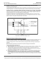


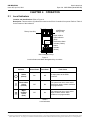


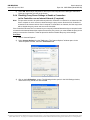
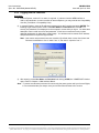


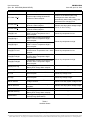

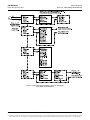

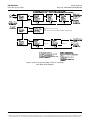
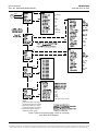


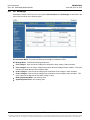

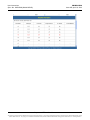
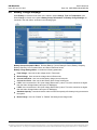
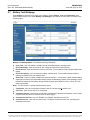


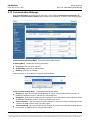


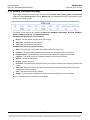
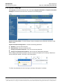


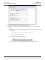

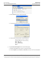
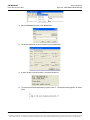


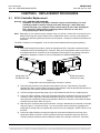


![[输入书名] - Emerson Network Power](http://vs1.manualzilla.com/store/data/005842917_1-6ec1a88a77b6fa212b87a12729f502af-150x150.png)

![[输入书名]](http://vs1.manualzilla.com/store/data/005783394_1-fc20c72617a19a0d7587a472ef1576a7-150x150.png)