1
37385
DTSC-200
ATS Controller
Installation
Software Version 1.0xxx
Manual 37385
Manual 37385
DTSC-200 - ATS Controller
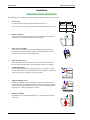
WARNING
Read this entire manual and all other publications pertaining to the work to be performed before installing, operating, or servicing this equipment. Practice all plant and safety instructions and precautions.
Failure to follow instructions can cause personal injury and/or property damage.
The engine, turbine, or other type of prime mover should be equipped with an overspeed (overtemperature, or overpressure, where applicable) shutdown device(s), that operates totally independently of the
prime mover control device(s) to protect against runaway or damage to the engine, turbine, or other
type of prime mover with possible personal injury or loss of life should the mechanical-hydraulic governor(s) or electric control(s), the actuator(s), fuel control(s), the driving mechanism(s), the linkage(s),
or the controlled device(s) fail.
Any unauthorized modifications to or use of this equipment outside its specified mechanical, electrical,
or other operating limits may cause personal injury and/or property damage, including damage to the
equipment. Any such unauthorized modifications: (i) constitute "misuse" and/or "negligence" within
the meaning of the product warranty thereby excluding warranty coverage for any resulting damage,
and (ii) invalidate product certifications or listings.
CAUTION
To prevent damage to a control system that uses an alternator or battery-charging device, make sure
the charging device is turned off before disconnecting the battery from the system.
Electronic controls contain static-sensitive parts. Observe the following precautions to prevent damage to these parts.
•
Discharge body static before handling the control (with power to the control turned off, contact a
grounded surface and maintain contact while handling the control).
•
Avoid all plastic, vinyl, and Styrofoam (except antistatic versions) around printed circuit boards.
•
Do not touch the components or conductors on a printed circuit board with your hands or with
conductive devices.
OUT-OF-DATE PUBLICATION
This publication may have been revised or updated since this copy was produced. To verify that you
have the latest revision, be sure to check the Woodward website:
http://www.woodward.com/pubs/current.pdf
The revision level is shown at the bottom of the front cover after the publication number. The latest
version of most publications is available at:
http://www.woodward.com/publications
If your publication is not there, please contact your customer service representative to get the latest
copy.
Important definitions
WARNING
Indicates a potentially hazardous situation that, if not avoided, could result in death or serious injury.
CAUTION
Indicates a potentially hazardous situation that, if not avoided, could result in damage to equipment.
NOTE
Provides other helpful information that does not fall under the warning or caution categories.
Woodward reserves the right to update any portion of this publication at any time. Information provided by Woodward is believed to be
correct and reliable. However, Woodward assumes no responsibility unless otherwise expressly undertaken.
© Woodward
All Rights Reserved.
Page 2/41
© Woodward
Manual 37385
DTSC-200 - ATS Controller
Revision History
Rev. Date
NEW 07-12-12
Editor
TP
Changes
Release
Content
CHAPTER 1. GENERAL INFORMATION..........................................................................................6
CHAPTER 2. ELECTROSTATIC DISCHARGE AWARENESS ..............................................................7
CHAPTER 3. HOUSING ................................................................................................................8
Panel Cutout ...........................................................................................................................................8
Dimensions .............................................................................................................................................9
Installation .............................................................................................................................................10
Screw Kit Installation.............................................................................................................................11
CHAPTER 4. WIRING DIAGRAM .................................................................................................12
CHAPTER 5. CONNECTIONS ......................................................................................................13
Power Supply ........................................................................................................................................14
Earth Ground.........................................................................................................................................14
Voltage Measuring (FlexRange) ...........................................................................................................15
Voltage Measuring: Source 1 .....................................................................................................15
Voltage Measuring: Source 2 .....................................................................................................20
Current Measuring ................................................................................................................................25
Load ............................................................................................................................................25
Discrete Inputs ......................................................................................................................................27
Discrete Inputs: Bipolar Signals..................................................................................................27
Discrete Inputs: Operation Logic ................................................................................................29
Discrete Outputs (Control Outputs And LogicsManager) .....................................................................30
Interfaces ..............................................................................................................................................31
RS-485 Modbus RTU Slave .......................................................................................................31
CAN Bus (FlexCAN) ...................................................................................................................32
DPC - Direct Configuration Cable...............................................................................................34
CHAPTER 6. TECHNICAL DATA .................................................................................................35
CHAPTER 7. ENVIRONMENTAL DATA .........................................................................................38
CHAPTER 8. ACCURACY ...........................................................................................................39
APPENDIX A. RECOMMENDED POWER SUPPLY UNITS ...............................................................40
© Woodward
Page 3/41
Manual 37385
DTSC-200 - ATS Controller
Illustrations and Tables
Illustrations
Figure 3-1: Housing - panel-board cutout.................................................................................................................................. 8
Figure 3-2: Housing - dimensions.............................................................................................................................................. 9
Figure 3-3: Housing - drill plan ............................................................................................................................................... 11
Figure 4-1: Wiring diagram ..................................................................................................................................................... 12
Figure 5-1: Power supply......................................................................................................................................................... 14
Figure 5-2: Power supply - crank waveform at maximum load ............................................................................................... 14
Figure 5-3: Earth ground.......................................................................................................................................................... 14
Figure 5-4: Voltage measuring - source 1................................................................................................................................ 15
Figure 5-5: Voltage measuring -source 1 PT windings, 3ph 4w.............................................................................................. 16
Figure 5-6: Voltage measuring -source 1 measuring inputs, 3ph 4w ....................................................................................... 16
Figure 5-7: Voltage measuring - source 1 PT windings, 3ph 3w............................................................................................. 17
Figure 5-8: Voltage measuring -source 1 measuring inputs, 3ph 3w ....................................................................................... 17
Figure 5-9: Voltage measuring - source 1 PT windings, 1ph 3w............................................................................................. 18
Figure 5-10: Voltage measuring -source 1 measuring inputs, 1ph 3w ..................................................................................... 18
Figure 5-11: Voltage measuring - source 1 PT windings, 1ph 2w ........................................................................................... 19
Figure 5-12: Voltage measuring -source 1 measuring inputs, 1ph 2w ..................................................................................... 19
Figure 5-13: Voltage measuring - source 2.............................................................................................................................. 20
Figure 5-14: Voltage measuring - source 2 PT windings, 3ph 4w ........................................................................................... 21
Figure 5-15: Voltage measuring -source 2 measuring inputs, 3ph 4w ..................................................................................... 21
Figure 5-16: Voltage measuring - source 2 PT windings, 3ph 3w ........................................................................................... 22
Figure 5-17: Voltage measuring -source 2 measuring inputs, 3ph 3w ..................................................................................... 22
Figure 5-18: Voltage measuring - source 2 PT windings, 1ph 3w ........................................................................................... 23
Figure 5-19: Voltage measuring -source 2 measuring inputs, 1ph 3w ..................................................................................... 23
Figure 5-20: Voltage measuring - source 2 PT windings, 1ph 2w ........................................................................................... 24
Figure 5-21: Voltage measuring -source 2 measuring inputs, 1ph 2w ..................................................................................... 24
Figure 5-22: Current measuring - load..................................................................................................................................... 25
Figure 5-23: Current measuring - load, L1 L2 L3.................................................................................................................... 26
Figure 5-24: Current measuring - load, Phase Lx .................................................................................................................... 26
Figure 5-25: Discrete inputs - alarm/control input - positive signal ....................................................................................... 27
Figure 5-26: Discrete inputs - alarm/control input - negative signal....................................................................................... 28
Figure 5-27: Discrete inputs - alarm/control inputs - operation logic ...................................................................................... 29
Figure 5-28: Discrete outputs................................................................................................................................................... 30
Figure 5-29: Interface .............................................................................................................................................................. 31
Figure 5-30: RS-485 Modbus - connection for half-duplex operation..................................................................................... 31
Figure 5-31: RS-485 Modbus - connection for full-duplex operation...................................................................................... 31
Figure 5-32: Interfaces - CAN bus (FlexCAN) ....................................................................................................................... 32
Figure 5-33: Interfaces - CAN bus - wiring of shielding ......................................................................................................... 32
Figure 5-34: Interfaces - CAN bus - termination ..................................................................................................................... 32
Page 4/41
© Woodward
Manual 37385
DTSC-200 - ATS Controller
Tables
Table 1-1: Manual - overview.................................................................................................................................................... 6
Table 3-1: Housing - panel cutout.............................................................................................................................................. 8
Table 5-1: Conversion chart - wire size ................................................................................................................................... 13
Table 5-2: Power supply - terminal assignment....................................................................................................................... 14
Table 5-3: Earth ground - terminal assignment........................................................................................................................ 14
Table 5-4: Voltage measuring - terminal assignment - source 1 .............................................................................................. 15
Table 5-5: Voltage measuring - terminal assignment - source 1, 3ph 4w ................................................................................ 16
Table 5-6: Voltage measuring - terminal assignment - source 1, 3ph 3w ................................................................................ 17
Table 5-7: Voltage measuring - terminal assignment - source 1, 1ph 3w ................................................................................ 18
Table 5-8: Voltage measuring - terminal assignment - source 1, 1ph 2w ................................................................................ 19
Table 5-9: Voltage measuring - terminal assignment - source 2 voltage ................................................................................. 20
Table 5-10: Voltage measuring - terminal assignment - source 2, 3ph 4w .............................................................................. 21
Table 5-11: Voltage measuring - terminal assignment - source 2, 3ph 3w .............................................................................. 22
Table 5-12: Voltage measuring - terminal assignment - source 2, 1ph 3w .............................................................................. 23
Table 5-13: Voltage measuring - terminal assignment - source 2, 1ph 2w .............................................................................. 24
Table 5-14: Current measuring - terminal assignment - load current....................................................................................... 25
Table 5-15: Current measuring - terminal assignment - load, L1 L2 L3.................................................................................. 26
Table 5-16: Current measuring - terminal assignment - load, Phase Lx .................................................................................. 26
Table 5-17: Discrete input - terminal assignment - alarm/control inputs................................................................................. 28
Table 5-18: Discrete outputs - terminal assignment................................................................................................................. 30
Table 5-19: RS-485 Modbus interface - terminal assignment.................................................................................................. 31
Table 5-20: CAN bus interface - terminal assignment............................................................................................................. 32
Table 5-21: Maximum CAN bus length................................................................................................................................... 33
© Woodward
Page 5/41
Manual 37385
DTSC-200 - ATS Controller
Chapter 1.
General Information
Type
DTSC-200 Series
DTSC-200 - Installation
DTSC-200 - Configuration
DTSC-200 - Operation
DTSC-200 - Application
DTSC-200 - Interfaces
Additional Manuals
LeoPC1 - User Manual
this manual Ö
English
German
37385
37386
37387
37388
37389
-
37146
GR37146
PC program for visualization, configuration, remote control, data logging, language upload, alarm and user management, and management of the event recorder. This manual describes the set up of the program and interfacing with the control unit.
LeoPC1 - Engineering Manual
37164
GR37164
PC program for visualization, configuration, remote control, data logging, language upload, alarm and user management, and management of the event recorder. This manual describes the configuration and customization of the program.
Table 1-1: Manual - overview
Intended Use The unit must only be operated in the manner described by this manual. The prerequisite for a
proper and safe operation of the product is correct transportation, storage, and installation as well as careful operation and maintenance.
NOTE
This manual has been developed for a unit fitted with all available options. Inputs/outputs, functions,
configuration screens, and other details described, which do not exist on your unit, may be ignored.
The present manual has been prepared to enable the installation and commissioning of the unit. Due to
the large variety of parameter settings, it is not possible to cover every combination. The manual is
therefore only a guide. In case of incorrect entries or a total loss of functions, the default settings may
be taken from the list of parameters enclosed in the configuration manual 37386.
Page 6/41
© Woodward
Manual 37385
DTSC-200 - ATS Controller
Chapter 2.
Electrostatic Discharge Awareness
All electronic equipment is static-sensitive, some components more than others. To protect these components
from static damage, you must take special precautions to minimize or eliminate electrostatic discharges.
Follow these precautions when working with or near the control.
1.
Before doing maintenance on the electronic control, discharge the static electricity on your body to
ground by touching and holding a grounded metal object (pipes, cabinets, equipment, etc.).
2.
Avoid the build-up of static electricity on your body by not wearing clothing made of synthetic materials.
Wear cotton or cotton-blend materials as much as possible because these do not store static electric charges as easily as synthetics.
3.
Keep plastic, vinyl, and Styrofoam materials (such as plastic or Styrofoam cups, cigarette packages, cellophane wrappers, vinyl books or folders, plastic bottles, etc.) away from the control, modules, and work
area as much as possible.
4.
Opening the control cover may void the unit warranty.
Do not remove the printed circuit board (PCB) from the control cabinet unless absolutely necessary. If
you must remove the PCB from the control cabinet, follow these precautions:
• Ensure that the device is completely voltage-free (all connectors have to be disconnected).
• Do not touch any part of the PCB except the edges.
• Do not touch the electrical conductors, connectors, or components with conductive devices or with
bare hands.
• When replacing a PCB, keep the new PCB in the plastic antistatic protective bag it comes in until you
are ready to install it. Immediately after removing the old PCB from the control cabinet, place it in the
antistatic protective bag.
CAUTION
To prevent damage to electronic components caused by improper handling, read and observe the precautions in Woodward manual 82715, Guide for Handling and Protection of Electronic Controls, Printed
Circuit Boards, and Modules.
© Woodward
Page 7/41
Manual 37385
DTSC-200 - ATS Controller
Chapter 3.
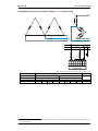
Housing
Panel Cutout
≡≡≡≡≡≡≡≡≡≡≡≡≡≡≡≡≡≡≡≡≡≡≡≡≡
B
b
b'
h' h H
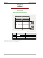
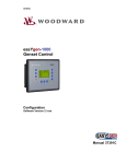
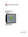
Figure 3-1: Housing - panel-board cutout
Measure
H
h
h'
B
b
b'
Description
Height
Width
Depth
Total
Panel cutout
Housing dimension
Total
Panel cutout
Housing dimension
Total
171 mm (6.73 in)
138 mm (5.43 in)
136 mm (5.35 in)
219 mm (8.62 in)
186 mm (7.32 in)
185 mm (7.28 in)
61 mm (2.40 in)
Tolerance
--+ 1.0 mm (0.04 in)
--+ 1.1 mm (0.04 in)
---
Table 3-1: Housing - panel cutout
The maximum permissible corner radius is 3.5 mm (0.14 in).
Refer to Figure 3-3 on page 11 for a cutout drawing.
Page 8/41
© Woodward
© Woodward
1 2 3 4 5 6 7 8 9 10 11 12 13 14
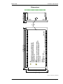
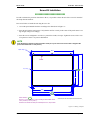
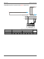
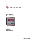
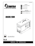
Dimensions
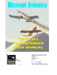
Cutout [WxH]:186 x 138 mm
Total [WxHxD]: 219 x 171 x 61 mm
Back view
15 16 17 18 19 20 21 22 23 24 25 26 27 28 29 30
2007-05-31 | DTSC-200 Dimensions DTSC200ww-2107-ab.skf
NOTE
Connected inductances (e.g. coils of operating current
or undervoltage tripping devices, auxiliary contactors
and power contactors) must be wired with an appropriate
interference protection.
WARNING
Before disconnecting the current transformer/CT secondary
connections or the connections of the current transformer/CT
at the device, ensure that the current transformer/CT
is short-circuited.
62 61 60 59 58 57 56 55 54 53 52 51 50 49 48 47 46 45 44 43 42 41 40 39 38 37 36 35 34 33 32 31
219 mm (8.6 in)
185 mm (7.3 in)
PC
Configuration
Port
Right view
61 mm (2.4 in)
50 mm (2 in)
Manual 37385
DTSC-200 - ATS Controller
Dimensions
≡≡≡≡≡≡≡≡≡≡≡≡≡≡≡≡≡≡≡≡≡≡≡≡≡
Figure 3-2: Housing - dimensions
Page 9/41
171 mm (6.7 in)
136 mm (5.4 in)
Manual 37385
DTSC-200 - ATS Controller
Installation
≡≡≡≡≡≡≡≡≡≡≡≡≡≡≡≡≡≡≡≡≡≡≡≡≡
For installation into a panel door with the fastening clamps, please proceed as follows:
1.
Panel cutout
Cut out the panel according to the dimensions in Figure 3-3.
B
b
Note: It is not necessary to drill the holes if the fastening clamps are used.
2.
Remove terminals
Loosen the wire connection terminal screws on the back of the unit and
remove the wire connection terminal strip if required.
3.
Insert screws in clamps
Insert the four clamping screws into the clamp inserts from the shown
side (opposite of the nut insert) until they are almost flush. Do not completely insert the screws into the clamp inserts.
4.
Insert unit into cutout
Insert the unit into the panel cutout. Verify that the unit fits correctly in
the cutout. If the panel cutout is not big enough, enlarge it accordingly.
5.
Attach clamp inserts
Re-install the clamp inserts by tilting the insert to a 45° angle. (1) Insert
the nose of the insert into the slot on the side of the housing. (2) Raise the
clamp insert so that it is parallel to the control panel.
6.
7.
Tighten clamping screws
Tighten the clamping screws (1) until the control unit is secured to the
control panel (2). Over tightening of these screws may result in the clamp
inserts or the housing breaking. Do not exceed the recommended tightening torque of 0.1 Nm (0.9 pound-force inches).
h H
2
1
1
2
Reattach terminals
Reattach the wire connection terminal strip (1) and secure them with the
side screws.
Page 10/41
© Woodward
Manual 37385
DTSC-200 - ATS Controller
Screw Kit Installation
≡≡≡≡≡≡≡≡≡≡≡≡≡≡≡≡≡≡≡≡≡≡≡≡≡
In order to enhance the protection from front to IP 65, it is possible to fasten the unit with a screw kit instead of
the clamp fastener hardware.
Proceed as follows to install the unit using the screw kit:
1. Cut out the panel and drill the holes according to the dimensions in Figure 3-3.
2. Insert the unit into the panel cutout. Verify that the unit fits correctly in the cutout. If the panel cutout is not
big enough, enlarge it accordingly.
3. Insert the screws and tighten to 0.6 Nm (5.3 pound-force inches) of torque. Tighten the screws with a crosswise pattern to ensure even pressure distribution.
NOTE
If the thickness of the panel sheet exceeds 2.5 mm (0.1 in), be sure to use screws with a length of the
panel sheet thickness + 4 mm (0.16 in).
Rmax: R 3,5
196,0
5,0
Cutout
8 x ø 4,5
138,0 148,0
69,0
5,0
5,0
5,0
93,0
181,0
186,0
191,0
Cutout dimension:
186 mm (+1.1 mm) x 138 mm (+1.0 mm) according to DIN 43700/IEC 61554
7.32 in (+0.045 in) x 5.43 in (+0.04 in)
2006-09-05 | DTSC-200 cutout+drillplan DTSC200ww-3606-ab.SKF
Unit will be mounted with 8 screws (P/N: LR02236) M4 x 6 mm, torque 0.6Nm.
Figure 3-3: Housing - drill plan
© Woodward
Page 11/41
Manual 37385
DTSC-200 - ATS Controller
Power supply input
0 Vdc
CAN-H
CAN-L
RS-485-B
RS-485-A'
RS-485
Isolated
full duplex
RS-485-B'
N.C.
../1 A or ../5 A
Load current L3
../1 A or ../5 A
Load current L2
../1 A or ../5 A
Load current L1
Earth ground
100 Vac
Source 1 voltage N
100 Vac
400 Vac
100 Vac
FlexRange
400 Vac
Source 1 voltage L3
Source 1 voltage L2
400 Vac
100 Vac
Source 1 voltage L1
400 Vac
100 Vac
Source 2 voltage N
100 Vac
400 Vac
100 Vac
FlexRange
400 Vac
Source 2 voltage L3
Source 2 voltage L2
400 Vac
100 Vac
Source 2 voltage L1
400 Vac
Subject to technical modifications.
DTSC-200 Automatic Transfer Switch Controller
Common
GND
Common (terminals 51 to 62)
Discrete output [R 9]
Command: open from source 2
position to neutral position
Discrete output [R 8]
Command: open from source 1
position to neutral position
Discrete output [R 7]
Command: close to
source 2 position
Discrete output [R 6]
Command: close to
source 1 position
Discrete output [R 5] Engine start contact
N.C.
Discrete output [R 4]
freely configuable
via LogicsManager
Discrete output [R 3] freely
configuable via LogicsManager
Discrete output [R 2] freely
configuable via LogicsManager
Discrete output [R 1] freely
configuable via LogicsManager
Common (terminals 32 - 34)
31 32 33 34 35 36 37 38 39 40 41 42 43 44 45 46 47 48 49 50 51 52 53 54 55 56 57 58 59 60 61 62
RS-485-A
Discrete input [DI 12] freely
12
configurable via LogicsManager
Discrete input [DI 11] freely
11
configurable via LogicsManager
Discrete input [DI 10] freely
10
configurable via LogicsManager
Discrete input [DI 9] freely
9
configurable via LogicsManager
Discrete input [DI 8] freely
8
configurable via LogicsManager
Discrete input [DI 7] freely
7
configurable via LogicsManager
Discrete input [DI 6] freely
6
configurable via LogicsManager
Discrete input [DI 5]
5
Inhibit ATS
Discrete input [DI 4] Reply from ATS limit
4
switch: Breaker in source 2 open position
Discrete input [DI 3] Reply from ATS limit
3
switch: Breaker in source 1 open position
Discrete input [DI 2] Reply from ATS limit
2
switch: Breaker in source 2 position
Discrete input [DI 1] Reply from ATS limit
1
switch: Breaker in source 1 position
LogicsManager
4 3 2 1
12/24 Vdc
30 29 28 27 26 25 24 23 22 21 20 19 18 17 16 15 14 13 12 11 10 9 8 7 6 5
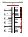
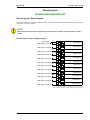
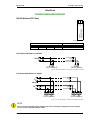
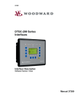
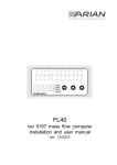
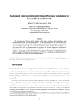
Chapter 4.
Wiring Diagram
2007-12-05 | DTSC-200 Terminal Diagram DTSCww-4907-ap.SKF
Figure 4-1: Wiring diagram
Page 12/41
© Woodward
Manual 37385
DTSC-200 - ATS Controller
Chapter 5.
Connections
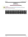
WARNING
All technical data and ratings indicated in this chapter are not definite! Only the values indicated in
Chapter 6: Technical Data on page 35 are valid!
The following chart may be used to convert square millimeters [mm²] to AWG and vice versa:
AWG
30
28
26
24
22
mm²
0.05
0.08
0.14
0.25
0.34
AWG
21
20
18
17
16
mm²
0.38
0.5
0.75
1.0
1.5
AWG
14
12
10
8
6
mm²
2.5
4
6
10
16
AWG
4
2
1
1/0
2/0
mm²
25
35
50
55
70
AWG
3/0
4/0
300MCM
350MCM
500MCM
mm²
95
120
150
185
240
AWG
600MCM
750MCM
1000MCM
mm²
300
400
500
Table 5-1: Conversion chart - wire size
© Woodward
Page 13/41
Manual 37385
DTSC-200 - ATS Controller
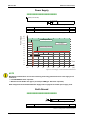
Power Supply
≡≡≡≡≡≡≡≡≡≡≡≡≡≡≡≡≡≡≡≡≡≡≡≡≡
48 49
12/24Vdc (6.5 to 40.0 Vdc)
6.5 to 40.0 Vdc
Power supply
0 Vdc
Figure 5-1: Power supply
Terminal
1
2
Description
12/24Vdc (6.5 to 40.0 Vdc), 15 W
0 Vdc reference potential
Amax
2.5 mm²
2.5 mm²
Power Supply
Table 5-2: Power supply - terminal assignment
[V]
12.0
Initial voltage = 10.5 Vdc
11.0
Continuous voltage range =
6.5 to 40.0 Vdc
10.0
9.0
Continuous voltage = min. 6.5 Vdc
8.0
7.0
6.0
5.0
0.0 Vdc for 10 ms
4.0
3.0
2.0
Time
1.0
0.0
-50
0
50
100
150
200
250
300
350
[ms]
Figure 5-2: Power supply - crank waveform at maximum load
NOTE
Woodward recommends to use one of the following slow-acting protective devices in the supply line to
terminal 63:
• Fuse NEOZED D01 6A or equivalent
• Miniature Circuit Breaker 6A / Type C (for example: ABB type: S271C6 or equivalent)
Refer to Appendix A: Recommended Power Supply Units on page 40 for suitable power supply units.
Earth Ground
14
≡≡≡≡≡≡≡≡≡≡≡≡≡≡≡≡≡≡≡≡≡≡≡≡≡
Earth ground
Figure 5-3: Earth ground
Terminal
14
Description
Earth ground connection
Amax
2.5 mm²
Table 5-3: Earth ground - terminal assignment
Page 14/41
© Woodward
Manual 37385
DTSC-200 - ATS Controller
Voltage Measuring (FlexRange)
≡≡≡≡≡≡≡≡≡≡≡≡≡≡≡≡≡≡≡≡≡≡≡≡≡
NOTE
DO NOT use both sets of voltage measuring inputs. The control unit will not measure voltage correctly
if the 100 V and 400 V inputs are utilized simultaneously.
NOTE
Woodward recommends protecting the voltage measuring inputs with slow-acting fuses rated for 2 to
6 A.
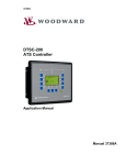
Voltage Measuring: Source 1
L1
L2
L3
100 Vac
400 Vac
100 Vac
400 Vac
100 Vac
400 Vac
100 Vac
400 Vac
100 Vac
400 Vac
100 Vac
400 Vac
100 Vac
400 Vac
100 Vac
L1 / Va
Voltage Source 1
(phase voltage)
400 Vac
15 16 17 18 19 20 21 22
N
L2 / Vb
L3 / Vc
N / Vcom
Figure 5-4: Voltage measuring - source 1
Terminal
15
16
17
18
19
20
21
22
Description
Source 1 voltage - phase N
Source 1 voltage - phase L3
Source 1 voltage - phase L2
Source 1 voltage - phase L1
100 Vac
400 Vac
100 Vac
400 Vac
100 Vac
400 Vac
100 Vac
400 Vac
Amax
2.5 mm²
2.5 mm²
2.5 mm²
2.5 mm²
2.5 mm²
2.5 mm²
2.5 mm²
2.5 mm²
Table 5-4: Voltage measuring - terminal assignment - source 1
NOTE
The 100 V input terminals must be used, if parameter "S1 voltage transf. secondary" (refer to Configuration Manual 37386) is configured with a value between 50 and 130 V for proper measurement.
The 400 V input terminals must be used, if parameter "S1 voltage transf. secondary" (refer to Configuration Manual 37386) is configured with a value between 131 and 480 V for proper measurement.
© Woodward
Page 15/41
Manual 37385
DTSC-200 - ATS Controller
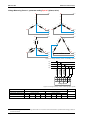
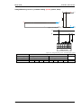
Voltage Measuring: Source 1, parameter setting '3ph 4w' (3phase, 4wire)
A
A
L1
L1
A1
A1
A2
A2
A5
A6
N
C2
C6
C1
B1
B5
B2
C2
B
C
A
B1
C1
L2
B
C
N
L3
L3
A2
A6
C
C2
B6
B5
C5
A2
N
C1
C6
A1
C5
N
C2
L1
A
C6
A5
L2
N
L1
A1
N B6
C5
B2
B2
B1
A5
C1
B
L2
A6
C
B
B6
B2
B5
B1
L2
N
L3
L3
N
Figure 5-5: Voltage measuring -source 1 PT windings, 3ph 4w
L1
L2
L3
N
22 21 20 19 18 17 16 15
[4] [1] [4] [1] [4] [1] [4] [1]
L1
L2
L3
N
Voltage 3Ph 4W
Figure 5-6: Voltage measuring -source 1 measuring inputs, 3ph 4w
3ph 4w
Rated voltage (range)
Measuring range (max.)
DTSC-200 terminal
Phase
Wiring terminals
[1] 100 V (50 to 130 Veff.)
[4] 400 V (131 to 480 Veff.)
[1] 0 to 150 Vac
[4] 0 to 600 Vac
21
19
17
15
22
20
18
16
L1
L2
L3
N
L1
L2
L3
N
Note
1
Table 5-5: Voltage measuring - terminal assignment - source 1, 3ph 4w
1
For different voltage systems, different wiring terminals have to be used. Incorrect measurements are possible if both voltage systems use
the same N terminal.
Page 16/41
© Woodward
Manual 37385
DTSC-200 - ATS Controller
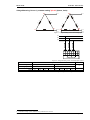
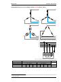
Voltage Measuring: Source 1, parameter setting '3ph 3w' (3phase, 3wire)
A
L1
L1
A
C6
A1
C5
C2
A2
A1
C1
A2
C2
A5
C1
C
B
B2
B1
L2
C
A6
B
B6
B5
B2
B1
L3
L2
L3
Figure 5-7: Voltage measuring - source 1 PT windings, 3ph 3w
L1
L2
L3
22 21 20 19 18 17 16 15
[4] [1] [4] [1] [4] [1] [4] [1]
L1
L2
L3
N
Voltage 3Ph 3W
Figure 5-8: Voltage measuring -source 1 measuring inputs, 3ph 3w
3ph 3w
Rated voltage (range)
Measuring range (max.)
DTSC-200 terminal
Phase
Wiring terminals
[1] 100 V (50 to 130 Veff.)
[4] 400 V (131 to 480 Veff.)
[1] 0 to 150 Vac
[4] 0 to 600 Vac
21
19
17
15
22
20
18
16
L1
L2
L3
--L1
L2
L3
---
Note
2
Table 5-6: Voltage measuring - terminal assignment - source 1, 3ph 3w
2
For different voltage systems, different wiring terminals have to be used.
© Woodward
Page 17/41
Manual 37385
DTSC-200 - ATS Controller
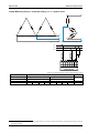
Voltage Measuring: Source 1, parameter setting '1ph 3w' (1phase, 3wire)
A
B5
C2
B6
B1
C1
L1
A1
A5
A2
A6
C6
B2
B6
N
C5
B5
B2
B1
C2
A
C
A1
A2
N
A5
A6
C1
L3
C6
N
C5
C
L3
N
L1
Figure 5-9: Voltage measuring - source 1 PT windings, 1ph 3w
L1
N
L3
22 21 20 19 18 17 16 15
[4] [1] [4] [1] [4] [1] [4] [1]
L1
L2
L3
N
Voltage 1Ph 3W
Figure 5-10: Voltage measuring -source 1 measuring inputs, 1ph 3w
1p 3w
Rated voltage (range)
Measuring range (max.)
DTSC-200 terminal
Phase
Wiring terminals
[1] 100 V (50 to 130 Veff.)
[4] 400 V (131 to 480 Veff.)
[1] 0 to 150 Vac
[4] 0 to 600 Vac
21
19
17
15
22
20
18
16
L1
N
L3
N
L1
N
L3
N
Note
3
Table 5-7: Voltage measuring - terminal assignment - source 1, 1ph 3w
3
For different voltage systems, different wiring terminals have to be used. Incorrect measurements are possible if both voltage systems use
the same N terminal.
Page 18/41
© Woodward
Manual 37385
DTSC-200 - ATS Controller
Voltage Measuring: Source 1, parameter setting '1ph 2w' (1phase, 2wire)
A
A
N
A1
A2
A5
A6
A1
B5
A2
B6
L1
N
N
L1
N
Figure 5-11: Voltage measuring - source 1 PT windings, 1ph 2w
L1
N
22 21 20 19 18 17 16 15
[4] [1] [4] [1] [4] [1] [4] [1]
L1
L2
L3
N
Voltage 1Ph 2W
Figure 5-12: Voltage measuring -source 1 measuring inputs, 1ph 2w
1ph 2w
Rated voltage (range)
Measuring range (max.)
DTSC-200 terminal
Phase
Wiring terminals
[1] 100 V (50 to 130 Veff.)
[4] 400 V (131 to 480 Veff.)
[1] 0 to 150 Vac
[4] 0 to 600 Vac
21
19
17
15
22
20
18
16
L1
N
N
N
L1
N
N
N
Note
3
Table 5-8: Voltage measuring - terminal assignment - source 1, 1ph 2w
© Woodward
Page 19/41
Manual 37385
DTSC-200 - ATS Controller
Voltage Measuring: Source 2
L1
L2
L3
100 Vac
400 Vac
100 Vac
400 Vac
100 Vac
400 Vac
100 Vac
400 Vac
100 Vac
400 Vac
100 Vac
400 Vac
100 Vac
400 Vac
100 Vac
L1 / Va
L2 / Vb
L3 / Vc
Voltage Source 2
(phase voltage)
400 Vac
23 24 25 26 27 28 29 30
N
N / Vcom
Figure 5-13: Voltage measuring - source 2
Terminal
23
24
25
26
27
28
29
30
Description
Source 2 voltage - phase N
Source 2 voltage - phase L3
Source 2 voltage - phase L2
Source 2 voltage - phase L1
100 Vac
400 Vac
100 Vac
400 Vac
100 Vac
400 Vac
100 Vac
400 Vac
Amax
2.5 mm²
2.5 mm²
2.5 mm²
2.5 mm²
2.5 mm²
2.5 mm²
2.5 mm²
2.5 mm²
Table 5-9: Voltage measuring - terminal assignment - source 2 voltage
NOTE
The 100 V input terminals must used, if parameter "S2 voltage transf. secondary" (refer to Configuration Manual 37386) is configured with a value between 50 and 130 V for proper measurement.
The 400 V input terminals must used, if parameter "S2 voltage transf. secondary" (refer to Configuration Manual 37386) is configured with a value between 131 and 480 V for proper measurement.
Page 20/41
© Woodward
Manual 37385
DTSC-200 - ATS Controller
Voltage Measuring: Source 2, parameter setting '3ph 4w' (3phase, 4wire)
A
A
L1
L1
A1
A1
A2
A2
A5
A6
N
C2
C6
C1
B1
B5
C2
B
C
A
B2
C1
L2
B1
B
C
N
L3
L3
A2
A6
C
C2
B6
B5
C5
A2
N
C1
C6
A1
C5
N
C2
L1
A
C6
A5
L2
N
L1
A1
N B6
C5
B2
B2
B1
A5
C1
B
L2
A6
C
B
B6
B2
B5
B1
L2
N
L3
L3
N
Figure 5-14: Voltage measuring - source 2 PT windings, 3ph 4w
L1
L2
L3
N
30 29 28 27 26 25 24 23
[4] [1] [4] [1] [4] [1] [4] [1]
L1
L2
L3
N
Voltage 3Ph 4W
Figure 5-15: Voltage measuring -source 2 measuring inputs, 3ph 4w
3ph 4w
Rated voltage (range)
Measuring range (max.)
DTSC-200 terminal
Phase
Wiring terminals
[1] 100 V (50 to 130 Veff.)
[4] 400 V (131 to 480 Veff.)
[1] 0 to 150 Vac
[4] 0 to 600 Vac
29
27
25
23
30
28
26
24
L1
L2
L3
N
L1
L2
L3
N
Note
4
Table 5-10: Voltage measuring - terminal assignment - source 2, 3ph 4w
4
For different voltage systems, different wiring terminals have to be used. Incorrect measurements are possible if both voltage systems use
the same N terminal.
© Woodward
Page 21/41
Manual 37385
DTSC-200 - ATS Controller
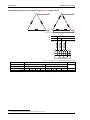
Voltage Measuring: Source 2, parameter setting '3ph 3w' (3phase, 3wire)
A
L1
L1
A
C6
A1
C5
C2
A2
A1
A2
C1
C2
A5
C1
C
B
B2
B1
L2
C
A6
B
B6
B5
B2
B1
L3
L2
L3
Figure 5-16: Voltage measuring - source 2 PT windings, 3ph 3w
L1
L2
L3
30 29 28 27 26 25 24 23
[4] [1] [4] [1] [4] [1] [4] [1]
L1
L2
L3
N
Voltage 3Ph 3W
Figure 5-17: Voltage measuring -source 2 measuring inputs, 3ph 3w
3ph 3w
Rated voltage (range)
Measuring range (max.)
DTSC-200 terminal
Phase
Wiring terminals
[1] 100 V (50 to 130 Veff.)
[4] 400 V (131 to 480 Veff.)
[1] 0 to 150 Vac
[4] 0 to 600 Vac
29
27
25
23
30
28
26
24
L1
L2
L3
--L1
L2
L3
---
Note
5
Table 5-11: Voltage measuring - terminal assignment - source 2, 3ph 3w
5
For different voltage systems, different wiring terminals have to be used.
Page 22/41
© Woodward
Manual 37385
DTSC-200 - ATS Controller
Voltage Measuring: Source 2, parameter setting '1ph 3w' (1phase, 3wire)
A
B5
C2
B6
B1
C1
L1
A1
A5
A2
A6
C6
B2
B6
N
C5
B5
B2
B1
C2
A
C
A1
A2
N
A5
A6
C1
L3
C6
N
C5
C
L3
N
L1
Figure 5-18: Voltage measuring - source 2 PT windings, 1ph 3w
L1
N
L3
30 29 28 27 26 25 24 23
[4] [1] [4] [1] [4] [1] [4] [1]
L1
L2
L3
N
Voltage 1Ph 3W
Figure 5-19: Voltage measuring -source 2 measuring inputs, 1ph 3w
1p 3w
Rated voltage (range)
Measuring range (max.)
DTSC-200 terminal
Phase
Wiring terminals
[1] 100 V (50 to 130 Veff.)
[4] 400 V (131 to 480 Veff.)
[1] 0 to 150 Vac
[4] 0 to 600 Vac
29
27
25
23
30
28
26
24
L1
N
L3
N
L1
N
L3
N
Note
6
Table 5-12: Voltage measuring - terminal assignment - source 2, 1ph 3w
6
For different voltage systems, different wiring terminals have to be used. Incorrect measurements are possible if both voltage systems use
the same N terminal.
© Woodward
Page 23/41
Manual 37385
DTSC-200 - ATS Controller
Voltage Measuring: Source 2, parameter setting '1ph 2w' (1phase, 2wire)
A
A
N
A1
A2
A5
A6
A1
B5
A2
B6
L1
N
N
L1
N
Figure 5-20: Voltage measuring - source 2 PT windings, 1ph 2w
L1
N
30 29 28 27 26 25 24 23
[4] [1] [4] [1] [4] [1] [4] [1]
L1
L2
L3
N
Voltage 1Ph 2W
Figure 5-21: Voltage measuring -source 2 measuring inputs, 1ph 2w
1p 2w
Rated voltage (range)
Measuring range (max.)
DTSC-200 terminal
Phase
Wiring terminals
[1] 100 V (50 to 130 Veff.)
[4] 400 V (131 to 480 Veff.)
[1] 0 to 150 Vac
[4] 0 to 600 Vac
29
27
25
23
30
28
26
24
L1
N
N
N
L1
N
N
N
Note
6
Table 5-13: Voltage measuring - terminal assignment - source 2, 1ph 2w
Page 24/41
© Woodward
Manual 37385
DTSC-200 - ATS Controller
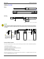
Current Measuring
≡≡≡≡≡≡≡≡≡≡≡≡≡≡≡≡≡≡≡≡≡≡≡≡≡
CAUTION
Before disconnecting the current transformer/CT secondary connections or the connections of the current transformer/CT at the device, ensure that the current transformer/CT is short-circuited.
Load
NOTE
Please connect the wires of the current transformer "L (x)" as near as possible to the unit.
NOTE
Generally, one line of the current transformers secondary is to be grounded.
L1
L2
L3
N
s2
s1
../{x} A
{x} = 1 or 5
G
s1 (k)
s2 (l)
L..
Note:
Connect the common
wires of the transformer
near the unit.
10 13 12 11
S1
..
S2
..
L..
../{x} A
s1 (k) - L3
../{x} A
s1 (k) - L2
../{x} A
s1 (k) - L1
Load current
(phase current)
Detail:
Connection of the transformers
s2 (l)
Figure 5-22: Current measuring - load
Terminal
10
11
12
13
Description
Load current - phases L1/L2/L3 - transformer terminals x2 (l)
Load current - phase L3 - transformer terminal s1 (k)
Load current - phase L2 - transformer terminal s1 (k)
Load current - phase L1 - transformer terminal s1 (k)
Amax
2.5 mm²
2.5 mm²
2.5 mm²
2.5 mm²
Table 5-14: Current measuring - terminal assignment - load current
© Woodward
Page 25/41
Manual 37385
DTSC-200 - ATS Controller
Current Measuring: Load, parameter setting 'L1 L2 L3'
IGen L1 IGen L2 IGen L3
IGround
IErd
L1
L2
L3
N
Figure 5-23: Current measuring - load, L1 L2 L3
Wiring terminals
L1 L2 L3
DTSC-200
Phase
13
L1
12
L2
Notes
11
L3
10
GND
Table 5-15: Current measuring - terminal assignment - load, L1 L2 L3
Current Measuring: Load, parameter setting 'Phase L1', 'Phase L2' & 'Phase L3'
IGen L1
IGen L2
IGen L3
L1
L1
L1
L2
L2
L2
L3
L3
L3
N
N
Phase L1
N
Phase L2
Phase L3
Figure 5-24: Current measuring - load, Phase Lx
Wiring terminals
Notes
Phase L1
DTSC-200
Phase
13
L1
12
---
11
---
10
GND
DTSC-200
Phase
13
---
12
L2
11
---
10
GND
DTSC-200
Phase
13
---
12
---
11
L3
10
GND
Phase L2
Phase L3
Table 5-16: Current measuring - terminal assignment - load, Phase Lx
Page 26/41
© Woodward
Manual 37385
DTSC-200 - ATS Controller
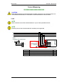
Discrete Inputs
≡≡≡≡≡≡≡≡≡≡≡≡≡≡≡≡≡≡≡≡≡≡≡≡≡
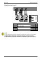
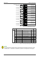
Discrete Inputs: Bipolar Signals
The discrete inputs are electrically isolated allowing for a bipolar connection. The discrete inputs are able to handle positive or negative signals.
NOTE
All discrete inputs must use the same polarity, either positive or negative signals, due to the common
ground.
Discrete Inputs: Positive / Negative Signal
Power supply Power suppply + (8 to 40 Vdc)
50
Power suppply + (8 to 40 Vdc)
52
Power suppply + (8 to 40 Vdc)
53
Power suppply + (8 to 40 Vdc)
54
Power suppply + (8 to 40 Vdc)
55
Power suppply + (8 to 40 Vdc)
56
Power suppply + (8 to 40 Vdc)
57
Power suppply + (8 to 40 Vdc)
58
Power suppply + (8 to 40 Vdc)
59
Power suppply + (8 to 40 Vdc)
60
Power suppply + (8 to 40 Vdc)
61
Power suppply + (8 to 40 Vdc)
62
51
Discrete input 1
Discrete input 2
Discrete input 3
Discrete input 4
Discrete input 5
Discrete input 6
Discrete input 7
Discrete input 8
Discrete input 9
Discrete input 10
Discrete input 11
Discrete input 12
Figure 5-25: Discrete inputs - alarm/control input - positive signal
© Woodward
Page 27/41
Manual 37385
DTSC-200 - ATS Controller
50
Power suppply + (8 to 40 Vdc)
Power supply -
51
Power supply -
52
Power supply -
53
Power supply -
54
Power supply -
55
Power supply -
56
Power supply -
57
Power supply -
58
Power supply -
59
Power supply -
60
Power supply -
61
Power supply -
62
Discrete input 1
Discrete input 2
Discrete input 3
Discrete input 4
Discrete input 5
Discrete input 6
Discrete input 7
Discrete input 8
Discrete input 9
Discrete input 10
Discrete input 11
Discrete input 12
Figure 5-26: Discrete inputs - alarm/control input - negative signal
Terminal
Description
Com. Signal
50
Amax
Type Ø
51
Discrete input [DI 1]
52
Discrete input [DI 2]
53
Discrete input [DI 3]
54
Discrete input [DI 4]
55
56
57
Discrete input [DI 5]
Discrete input [DI 6]
Discrete input [DI 7]
[S1] Reply from ATS limit switch:
Breaker in source 1 position
[S2] Reply from ATS limit switch:
Breaker in source 2 position
[S1O] Reply from ATS limit switch:
Breaker in source 2 open position
[S2O] Reply from ATS limit switch:
Breaker in source 1 open position
Inhibit ATS
Alarm input (programmable)
Alarm input (programmable)
58
Discrete input [DI 8]
Alarm input (programmable)
59
Discrete input [DI 9]
Alarm input (programmable)
60
NC
2.5 mm²
NC
2.5 mm²
NC
2.5 mm²
NC
2.5 mm²
SW (NC)
SW
SW
2.5 mm²
2.5 mm²
2.5 mm²
SW
2.5 mm²
SW
2.5 mm²
Discrete input [DI 10] Alarm input (programmable)
SW
2.5 mm²
61
Discrete input [DI 11] Alarm input (programmable)
SW
2.5 mm²
62
Discrete input [DI 12] Alarm input (programmable)
SW
2.5 mm²
SW-switchable via the software, [NO]-type 1 (N.O./make contact), [NC] -type 2 (N.C./break contact)
Table 5-17: Discrete input - terminal assignment - alarm/control inputs
NOTE
The discrete inputs for the breaker position reply messages (DIs 1 through 4) are fixed to N.C. and are
evaluated as N.C., i.e. the breaker is considered as "in position" if the respective DI is de-energized.
Page 28/41
© Woodward
Manual 37385
DTSC-200 - ATS Controller
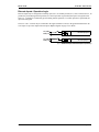
Discrete Inputs: Operation Logic
Discrete inputs may be configured to normally open (N.O.) or normally closed (N.C.) states. In the state N.O., no
potential is present during normal operation; if a control operation is performed, the input is energized. In the
state N.C., a potential is continuously present during normal operation; if a control operation is performed, the
input is de-energized.
The N.O. or N.C. contacts may be connected to the signal terminal as well as to the ground terminal of the discrete input. See previous chapter Discrete Inputs: Bipolar Signals on page 27 for details.
Vdc (GND)
GND (Vdc)
Discrete input (N.O.)
Vdc (GND)
GND (Vdc)
Discrete input (N.C.)
Figure 5-27: Discrete inputs - alarm/control inputs - operation logic
© Woodward
Page 29/41
Manual 37385
DTSC-200 - ATS Controller
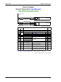
Discrete Outputs
(Control Outputs And LogicsManager)
≡≡≡≡≡≡≡≡≡≡≡≡≡≡≡≡≡≡≡≡≡≡≡≡≡
external device
external device
B A
external device
Relay output
A B A
max. 250 Vac/dc
Relay output
Figure 5-28: Discrete outputs
Terminal
Term. Com.
A
32
33
34
A
35
37
39
41
A
B
31
B
36
40
B
43
42
45
44
47
46
49
48
Description
Amax
Type Ø
Form A, common contact
SW 2.5 mm²
Discrete output [R 1]
LogicsManager
SW 2.5 mm²
Discrete output [R 2]
LogicsManager
SW 2.5 mm²
Discrete output [R 3]
LogicsManager
Type Ø
Form C, separate contacts
NC 2.5 mm²
Discrete output [R 4]
LogicsManager
NO 2.5 mm²
Discrete output [R 4]
NO 2.5 mm²
Discrete output [R 5]
Engine start
NC 2.5 mm²
Discrete output [R 5]
Type Ø
Form A, separate contacts
[C1] Command:
NO 2.5 mm²
Discrete output [R 6]
close to source 1 position
[C2] Command:
NO 2.5 mm²
Discrete output [R 7]
close to source 2 position
[C1O] Command:
NO 2.5 mm²
Discrete output [R 8]
open from source 1 to neutral position
[C2O] Command:
NO 2.5 mm²
Discrete output [R 9]
open from source 2 to neutral position
LogicsManager..using the function LogicsManager it is possible to freely program the relays
SW-switchable via the software, [NO]-type 1 (N.O./make contact), [NC]-type 1 (N.C./break contact)
Table 5-18: Discrete outputs - terminal assignment
Page 30/41
© Woodward
Manual 37385
DTSC-200 - ATS Controller
Interfaces
≡≡≡≡≡≡≡≡≡≡≡≡≡≡≡≡≡≡≡≡≡≡≡≡≡
8
RS-485-A'
RS-485-B'
RS-485-B
7
RS-485
Modbus RTU Slave
(isolated, full duplex)
6
Interface
5
RS-485-A
RS-485 Modbus RTU Slave
Figure 5-29: Interface
Terminal
Description
5
6
7
8
RS-485-A
RS-485-B
RS-485-A'
RS-485-B'
RS-485, Modbus RTU Slave
Table 5-19: RS-485 Modbus interface - terminal assignment
Half-Duplex with Modbus on RS-485
A
Master
B
120 Ω
120 Ω
7 8
DTSC (Slave 1)
7 8
DTSC (Slave n)
Figure 5-30: RS-485 Modbus - connection for half-duplex operation
Full-Duplex with Modbus on RS-485
A
Tx
B
Master
A'
Rx
B'
120 Ω
120 Ω
120 Ω
120 Ω
5 6 7 8
Tx
Rx
DTSC (Slave 1)
5 6 7 8
Tx
Rx
DTSC (Slave n)
Figure 5-31: RS-485 Modbus - connection for full-duplex operation
NOTE
Please note that the DTSC must be configured for half- or full-duplex configuration (refer to parameter 3173 in the Configuration Manual 37385).
© Woodward
Page 31/41
Manual 37385
DTSC-200 - ATS Controller
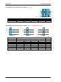
CAN Bus (FlexCAN)
3
CAN-L
4
Wiring
CAN-H
CAN bus (FlexCAN)
Figure 5-32: Interfaces - CAN bus (FlexCAN)
Terminal
3
4
Description
Amax
CAN-L 2.5 mm²
CAN-H 2.5 mm²
CAN bus (FlexCAN)
Table 5-20: CAN bus interface - terminal assignment
Shielding
Shield
3
4
CAN-L
CAN-H
CAN-L
easYgen
CAN-H
0.01 µF
400 Vac
Interface
CAN bus
1 MOhm
Figure 5-33: Interfaces - CAN bus - wiring of shielding
NOTE
Please note that the CAN bus must be terminated with a resistor, which corresponds to the impedance
of the cable (e.g. 120 Ohms, 1/4 W) at both ends. The termination resistor is connected between CAN-H
and CAN-L.
Note:
We recommend for very critical EMC
conditions (many noise sources with
high noise levels) and high transmission
rates to use the "Split Termination
Concept", i.e. dividing the termination
resistor into 2x60 Ohms with a center tap
connected to ground via a capacitor
of 10 - 100 nF.
GND
CAN-L
Termination
resistor
CAN-H
GND
CAN-L
CAN-H
~60 Ohms
CAN-L
Termination
resistor
CAN-H
~60 Ohms
10 ~ 100 nF
Note:
The termination has to be
performed with a resisitance,
which corresponds to the
impedance of the used cable
(e.g 120 Ohms)
easYgen
CAN bus
CAN bus
CAN bus
Figure 5-34: Interfaces - CAN bus - termination
Possible CAN Bus Problems
If no data is transmitted on the CAN bus, check the following for common CAN bus communication problems:
• T structure bus is utilized
• CAN-L and CAN-H are interchanged
• Not all devices on the bus are using identical Baud rates
• Terminating resistor are missing
• Baud rate to high for wiring length
• The CAN bus cable is co-routed with power cables
Woodward recommends the use of twisted-pair cables for the CAN bus (i.e.: Lappkabel Unitronic LIYCY (TP)
2×2×0.25, UNITRONIC-Bus LD 2×2×0.22).
Page 32/41
© Woodward
Manual 37385
DTSC-200 - ATS Controller
Maximum CAN bus Length
The maximum length of the communication bus wiring is dependent on the configured Baud rate. Refer to Table
5-21 for the maximum bus length (Source: CANopen; Holger Zeltwanger (Hrsg.); 2001 VDE VERLAG GMBH,
Berlin und Offenbach; ISBN 3-8007-2448-0).
Baud rate
1000 kbit/s
800 kbit/s
500 kbit/s
125 kbit/s
50 kbits/s
20 kbit/s
Max. length
25 m
50 m
100 m
250 m
1000 m
2500 m
Table 5-21: Maximum CAN bus length
The maximum specified length for the communication bus wiring might not be achieved if poor quality wire is
utilized, there is high contact resistance, or other conditions exist. Reducing the baud rate may overcome these issues.
© Woodward
Page 33/41
Manual 37385
DTSC-200 - ATS Controller
DPC - Direct Configuration Cable
The easYgen provides a configuration interface for connecting a computer via the DPC (direct configuration cable). The configuration interface is the RJ45 socket on the side of the easYgen housing.
NOTE
Configuration with the direct configuration cable DPC (P/N 5417-557) is possible. A laptop/PC, the DPC
cable, the program LeoPC1 version 3.1.1 or higher (included on CD Rom with control unit), and the
proper configuration files are required.
NOTE
The connection cable delivered with the DPC must be used between DPC and easYgen to ensure
proper functionality of the easYgen. An extension or utilization of different cable types for the connection between easYgen and DPC may result a malfunction of the easYgen. This may possibly result in
damage to components of the system. If an extension of the data connection line is required, only the
serial cable (RS-232) between DPC and laptop/PC may be extended. It is recommended to use an industry standard cable for this.
NOTE
For a continuous operation with the direct configuration cable DPC (e.g. remote control of the easYgen), it is required to use at least revision F (P/N 5417-557 Rev. F) of the DPC. When using a DPC of an
earlier revision, problems may occur in continuous operation. It is recommended to use an industry
standard serial (RS-232) cable to connect the DPC with the laptop/PC for continuous operation. The
shield connector (6.3mm tab connector) at the DPC of revision F (P/N 5417-557 Rev. F) and above must
be connected to ground.
Page 34/41
© Woodward
Manual 37385
DTSC-200 - ATS Controller
Chapter 6.
Technical Data
Nameplate ----------------------------------------------------------------------------------------------------1
2
3
4
5
6
7
8
9
S/N
S/N
S/N
P/N
REV
Details
Type
Type
UL
Serial number (numerical)
Date of production (YYMM)
Serial number (Barcode)
Item number
Item revision number
Technical data
Description (short)
Description (long)
UL sign
Measuring values, voltages ----------------------------------------------------------------------------- /Δ
- Measuring voltages
100 V
Rated value (Vrated) ....................................... 69/120 Vac
Maximum value (Vmax) ....................... max. 86/150 Vac
Rated voltage phase – ground ........................... 150 Vac
Rated surge voltage..............................................2.5 kV
-
400 V
Rated value (Vrated) ..................................... 277/480 Vac
Maximum value (Vmax) ..................... max. 346/600 Vac
Rated voltage phase – ground ........................... 300 Vac
Rated surge voltage..............................................4.0 kV
Linear measuring range ..................................................................................... 1.25 × Vrated
Measuring frequency ................................................................. 50/60 Hz (40.0 to 70.0 Hz)
Accuracy.................................................................................................................... Class 1
Input resistance per path
100 V............................................................... 0.498 MΩ
400 V.................................................................. 2.0 MΩ
Maximum power consumption per path ................................................................ < 0.15 W
Measuring values, currents -----------------------------------------------------------------------isolated
- Measuring current
[1] Rated value (Irated)............................................. ../1 A
[5] Rated value (Irated)............................................ ../5 A
-
Accuracy.................................................................................................................... Class 1
Linear measuring range
Load (terminals 10 through 13) .......................3.0 × Irated
Maximum power consumption per path ...............................................................< 0.15 VA
Rated short-time current (1 s)
[1]...................................................................50.0 × Irated
[5]...................................................................10.0 × Irated
Ambient variables -------------------------------------------------------------------------------------------- Power supply ......................................................12/24 Vdc (6.5 to 40.0 Vdc; not buffered)
Battery ground (terminal 2) must be grounded to the chassis
- Inrush current .....................................................................................max. 50 A peak, 1 ms
- Input capacitance ..................................................................................................... 2000 µF
- Intrinsic consumption ............................................................................................ max. 8 W
in power save mode (backlight, relays off) .............. 3 W
- Degree of pollution..............................................................................................................2
© Woodward
Page 35/41
Manual 37385
DTSC-200 - ATS Controller
Discrete inputs ---------------------------------------------------------------------------------------isolated
- Input range (VCont, digital input).....................................Rated voltage 12/24 Vdc (8 to 40 Vdc)
- Input resistance ..............................................................................................approx. 20 kΩ
Discrete outputs Group A [R 1-4] --------------------------------------------------------------- isolated
- Contact material ........................................................................................................AgCdO
- General purpose (GP) (VCont, relay output)
AC ...................................................2.00 Aac@250 Vac
DC .................................................... 2.00 Adc@24 Vdc
0.36 Adc@125 Vdc
0.18 Adc@250 Vdc
- Pilot Duty (PD) (VCont, relay output)
DC .................................................... 1.00 Adc@24 Vdc
0.22 Adc@125 Vdc
0.10 Adc@250 Vdc
- B300
Discrete outputs Engine Start [R 5] ------------------------------------------------------------- isolated
- Contact material ................................................................................................. AgNi 90/10
- General purpose (GP) (VCont, relay output)
AC .................................................10.00 Aac@250 Vac
Discrete outputs Group B [R 6-9] ---------------------------------------------------------------- isolated
- Contact material ................................................................................................. AgNi 90/10
- General purpose (GP) (VCont, relay output)
AC .................................................10.00 Aac@250 Vac
Interface -------------------------------------------------------------------------------------------------------RS-485 interface ....................................................................................................isolated
- Insulation voltage.....................................................................................................500 Vac
- Version......................................................................................................................RS-485
- Signal level....................................................................................................................... 5V
-
CAN bus interface ................................................................................................ isolated
Insulation voltage.....................................................................................................500 Vac
Version................................................................................................................... CAN bus
Internal line termination...................................................................................Not available
Battery ---------------------------------------------------------------------------------------------------------- Type ............................................................................................................................. NiCd
- Durability (at operation without power supply)............................................approx. 5 years
- Battery field replacement ...................................................................................not possible
Page 36/41
© Woodward
Manual 37385
DTSC-200 - ATS Controller
Housing --------------------------------------------------------------------------------------------------------- Type....................................................................................................................... easYpack
- Dimensions (W × H × D) .......................................219 × 171 × 61 mm (8.6 × 6.7 × 2.4 in)
- Front cutout (W × H)............................................................... 186 [+1.1] × 138 [+1.0] mm
- Material.................................................................................... glass fiber-reinforced plastic
- Wiring..................................................................screw-plug-terminals 14 AWG / 2.5 mm²
- Recommended tightening torque.........................5 to 7 pound-force inches / 0.5 to 0.8 Nm
use 60/75 °C copper wire 14 AWG / 2.5 mm² only
use class 1 wire only or equivalent
- Weight ..............................................................................................approx. 800 g (1.75 lb)
Protection ------------------------------------------------------------------------------------------------------ Protection system..................................................................IP54 from front with clamp kit
IP65 from front with screw kit
IP20 from back
- Front folio................................................................................................. insulating surface
- EMC test (CE) ............................................... tested according to applicable EN guidelines
- Listings ........................................................ CE marking; UL listing for ordinary locations
- Type approval.................................. UL/cUL listed, Ordinary Locations, File No.: 231544
© Woodward
Page 37/41
Manual 37385
DTSC-200 - ATS Controller
Chapter 7.
Environmental Data
Dynamics ------------------------------------------------------------------------------------------------------- Frequency Range – Sine Sweep......................................................................5Hz to 150Hz
- Acceleration ............................................................................................................ 4G
- Frequency Range - Random..........................................................................10Hz to 500Hz
- Power Density ........................................................................................... 0,015G²/Hz
- RMS Value.................................................................................................. 1,04 Grms
- Standards...............................................................................................................................
EN 60255-21-1 (EN 60068-2-6, Fc)
EN 60255-21-3
Lloyd’s Register, Vibration Test2
SAEJ1455 Chasis Data
MIL-STD 810F, M514.5A, Cat.4,
Truck/Trailer tracked-restrained
cargo, Fig. 514.5-C1
Shock ------------------------------------------------------------------------------------------------------------ ....................................................................................................40G, Sawtooth Puls, 11ms
- Standards...............................................................................................................................
EN 60255-21-2
MIL-STD 810F, M516.5, Procedure 1
Temperature --------------------------------------------------------------------------------------------------- Cold, Dry Heat (storage)........................................................-30°C (-22°F) / 80°C (176°F)
- Cold, Dry Heat (operating) .....................................................-20°C (-4°F) / 60 °C (140°F)
- Standards...............................................................................................................................
IEC 60068-2-2, Test Bb and Bd
IEC 60068-2-1, Test Ab and Ad
Humidity -------------------------------------------------------------------------------------------------------- ..........................................................................................................60°C, 95% RH, 5 days
- Standards...............................................................................................................................
IEC 60068-2-30, Test Db
Altitude ---------------------------------------------------------------------------------------------------------- Maximum operating altitude .....................................................................2000 m (6,500 ft)
Page 38/41
© Woodward
Manual 37385
DTSC-200 - ATS Controller
Chapter 8.
Accuracy
Measuring value
Display
Accuracy
Notes
15.0 to 85.0 Hz
40.0 to 85.0 Hz
0.1 %
0.1 %
0 to 650 kV
0 to 650 kV
1%
1%
Transformer ratio selectable
Transformer ratio selectable
0 to 32,000 A
0 to 32,000 A
1%
1%
Slave pointer
-2 to 2 GW
2%
Accuracy depends on the
configured transformer ratios
-2 to 2 Gvar
2%
Accuracy depends on the
configured transformer ratios
lag0.00 to 1.00
to lead0.00
2%
-
1%
not calibrated
-
Frequency
Source 1
Source 2
fL1N, fL2N, fL3N
fL1N, fL2N, fL3N
-
Voltage
Source 1
Source 2
VL1N, VL2N, VL3N,
VL1N, VL2N, VL3N,
Current
Load
Max. value
IL1, IL2, IL3
IL1, IL2, IL3
Real power
Current total real power value
Reactive power
Current value in L1, L2, L3
cos φ
Current value cos φL1
Miscellaneous
Real energy
Battery voltage
0 to 4,200 GWh
6.5 to 40 V
Reference conditions (to measure the accuracy):
• Input voltage.............................sinusoidal rated voltage
• Input current .............................sinusoidal rated current
• Frequency .................................rated frequency +/- 2 %
• Power supply ............................rated voltage +/- 2 %
• Power factor cos φ....................1.00
• Ambient temperature ................23 °C +/- 2 K
• Warm-up period .......................20 minutes
© Woodward
Page 39/41
Manual 37385
DTSC-200 - ATS Controller
Appendix A.
Recommended Power Supply Units
Woodward recommends the use of the following external power supply units:
•
•
Mean Well: DR-30-24
Phoenix Contact: MINI-PS-100-240AC/24DC/1
An external buffered power supply solution may be achieved using the following devices:
2x Phoenix Contact: MINI-PS-100-240AC/24DC/1
1x Phoenix Contact: Quint-Buffer/24DC/20
Page 40/41
© Woodward
We appreciate your comments about the content of our publications.
Please send comments to: [email protected]
Please include the manual number from the front cover of this publication.
Woodward GmbH
Handwerkstrasse 29 - 70565 Stuttgart - Germany
Phone +49 (0) 711 789 54-0 • Fax +49 (0) 711 789 54-100
[email protected]
Homepage
http://www.woodward.com/power
Woodward has company-owned plants, subsidiaries, and branches, as well as authorized
distributors and other authorized service and sales facilities throughout the world.
Complete address/phone/fax/e-mail information
for all locations is available on our website (www.woodward.com).
2007/12/Stuttgart