1
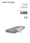
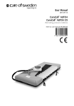
DEER WARNING SYSTEM
OPERATING DOCUMENTATION AND SETUP
June 2011
H:\Projects\7332\Task 2 Existing System Retrofit\System Operations.doc
TABLE OF CONTENTS
1. Overview ...................................................................................... 1
2. System Setup .............................................................................. 1
Solar Panel Orientation ................................................................................................... 1
Detectors ......................................................................................................................... 2
Sign Programming .......................................................................................................... 2
3. Testing ......................................................................................... 3
Power System Checks ..................................................................................................... 3
Activation Checks ........................................................................................................... 4
4. Maintenance ................................................................................ 4
Environment .................................................................................................................... 4
Detector Alignment ......................................................................................................... 4
Power System.................................................................................................................. 5
Communications ............................................................................................................. 5
5. Design Drawings and Documentation Appendices .................. 6
A. SIGN AND DETECTOR PLAN SHEETS ................................................................ 7
B. SYSTEM PHYSICAL LOCATIONS ...................................................................... 14
C. SIGN PROGRAMMING KEY ................................................................................ 16
D. DETECTOR USER MANUAL ............................................................................... 19
H:\Projects\7332\Task 2 Existing System Retrofit\System Operations.doc
Page 1
1. Overview
This document describes the setup and maintenance procedures for the Active Deer
Warning System near Marshall, MN. In some cases, it is necessary to refer to the
documentation provided by individual device manufacturers for specific procedures.
Manuals for these devices have been provided to Mn/DOT District personnel. The
detector manual is also included in this document as it requires periodic maintenance
checks.
The Deer Warning System consists of two subsystems: detector stations and signs. The
detector stations are placed along the roadside at distances of approximately 150 to 400
feet, depending on terrain conditions. Pairs of infrared beams are emitted by the
detectors and both must be broken for a detection “event” to occur. When an animal is
detected, a communications device connected to the detector receiver broadcasts a unique
identifier over a 915 MHz radio network.
The sign subsystems receive the identifier and then search a programmable list stored on
another communications device. If the identifier is found, it will then output a voltage to
a 12-volt relay which directs power to the LED beacon. The duration of beacon flash and
the list of associated detectors for each sign is user-programmable through a software
application.
Note: in June 2011, all the system’s communication devices (called Wavelogs) were
replaced with a version that draws power from the system’s large 12-volt battery rather
than a battery internal to the Wavelog. These new Wavelogs also added the capability to
“soft reset” the device. This reset restarts the device but does not clear its internal
memory, so programming remains intact . Push buttons were added to the enclosures that
activate the Wavelog’s reset feature.
2. System Setup
Solar Panel Orientation
All devices in the system are powered by 12-volt
batteries recharged by solar panels. Other than
connecting the leads for batteries and panels to the
charge controller, the only adjustment to be made is
panel orientation.
Panels should always face south to maximize the
amount of solar radiation absorbed by the panel.
Because of the latitude of the system near Marshall,
panels should be angled so that they are
perpendicular to the sun’s rays when it is at its
seasonal low in late December. In Marshall, MN
the proper angle is approximately 62 degrees below
horizontal. This orientation is shown in Figure 1.
H:\Projects\7332\Task 2 Existing System Retrofit\System Operations.doc
Horizontal
62 degrees
South
Page 2
Detectors
Proper alignment of detectors is critical for two reasons. First poorly aligned
detectors are more prone to “false positive” activations, which undermine the
credibility of the system and (if excessive) may cause failures in other system
components. Second, as signal conditions between the detectors deteriorate the
system will attempt to compensate by increasing the transmission power. If this
occurs during low power-input times (during winter overcast days, for example),
the battery reserves may be depleted, resulting in erratic system behavior.
The alignment process for the detectors is described in the device manual
provided in Appendix D. The following points should be considered when
reviewing this material:
1) The process will generally require two people to complete: one at the
transmit detector and one at the receiver.
2) Since signal strength can only be measured at the receiver site, a method
of communication (such as walkie-talkies) should be used by the
alignment team.
3) Transmitter alignment should be performed first (first upper, then lower
beams).
4) Although “beam blocking” cut-outs are provided in the manuals to isolate
the upper and lower beams for alignment, consider using these as a
template to make a cut-out of a more durable material, such as cardboard
or foam core. The paper cut-outs tend to tear and have difficulty staying
attached to the emitter.
5) When securing the covers, DO NOT over tighten the small screw at the
bottom. Use a precision-type screwdriver to tighten the screw enough to
keep the cover in place. Over tightening will result in stripped screw
heads and make servicing more difficult.
6) Annual checks should be made of detector alignment.
Sign Programming
Programming of the sign is accomplished
through the IndexManager application.
This software is designed to run on an
HP/Compaq IPaq or compatible device (not
supplied as part of the system). The
WavePort Compact Flash card must be
inserted into the IPaq’s CF slot or into the
slot on a compatible IPaq sleeve with an
appropriate slot.
To access the sign’s Wavelog, scroll to the
“Sign” tab on the bottom of the
H:\Projects\7332\Task 2 Existing System Retrofit\System Operations.doc
Page 3
IndexManager interface. The sign programming tab is shown in Figure 2.
Input the sign Wavelog’s ID into the box at the upper left using the on-screen
keyboard (tap the icon at the lower right to access the keyboard). Once you have
entered the ID, tap “Read Config” to verify that you can communicate to the
device.
To add a detector to the sign’s Associated Detector list, enter the ID into the box
below the list and tap “Add”. Detectors may be removed from the list by
selecting them and tapping “Remove”. No changes will be written to the
Wavelog’s memory until “Set Config” it tapped. Once programming changes are
made, the “Set Values OK” dialog will appear.
The duration of the sign’s flashing is set using the “Beacon Duration” box. Enter
the value in seconds into this box using the on-screen keyboard and tap “Set
Values” to save the change.
The most recent 100 activations of the sign can be viewed by tapping the “See
Events” button. A table will be displayed on-screen with the date and time of the
events. This table is recorded in a “first in-first out” fashion, so that the oldest
events are overwritten.
NOTE: Due to the low data transmission rates of the Wavelog, retrieving this
table may take several minutes.
Although similar controls are presented on the “Detector” Tab, only the “on/off”
control is functional in this version of the system. This may be used to prevent
detector or sign Wavelogs from accepting inputs or producing outputs.
3. Testing
Power System Checks
Once installed, the power system should be checked for proper operation. To
confirm that all components are operating, verify the following:
1) With direct sunlight, measure voltage on the solar panel leads. This
should be 17 volts or greater
2) Measure voltage at the battery leads, this should be 13 volts or greater.
3) Measure voltage at the load leads on the charge controller. This should be
12-14 Volts.
Annual checks of battery condition should also be made. Disconnect the battery
from the charge controller and connect a battery load tester to the battery
terminals. Verify that the battery reads “good” on the tester in the appropriate
load range.
H:\Projects\7332\Task 2 Existing System Retrofit\System Operations.doc
Page 4
Activation Checks
System activation can be checked by interrupting the beam between detector
stations. If a comprehensive check of all detectors and signs is to be performed,
the following procedure is recommended:
1) Position one person at each end of the system
2) Access the Wavelog for each of the signs and set its beacon duration to 5
seconds to minimize the time needed between testing each detection zone.
3) Interrupt the beam at each detector site
4) Observe the operation of each sign
5) When complete, reset the beacon duration at each sign to the desired flash
duration.
4. Maintenance
Environment
The area between detectors must be kept free of obstructions for the system to
operate properly. The primary concern will be grass or other vegetation growth
that may interfere with the infrared beams.
The installation area should be monitored on a monthly basis during the growing
season. The need for mowing will vary based on weather, vegetation type and
other conditions, but mowing will generally be needed every six to eight weeks.
Proper exposure of the solar panels is also important to system operation. Tree
growth should be monitored in the area and, where possible, trimmed to maximize
the hours of sunlight that the system will receive.
Detector Alignment
Wind induced vibration or other debris impacts may cause detector alignment to
“drift” over time, requiring periodic adjustment. While this should not be needed
in most cases, annual checks are recommended using the following procedure:
1) Remove the outer cover of the detector receiver
2) If the signal strength reads “Excellent” with a steady indication, no further
action is needed.
3) If the reading is other than Excellent or fluctuates, align the detectors
using the procedure described in the System Setup section.
H:\Projects\7332\Task 2 Existing System Retrofit\System Operations.doc
Page 5
Power System
Lifetime expectance of the solar panels and charge controllers is 15 years and
neither should require any maintenance. Should the panels become dirty, rinsing
with water is all that is required for cleaning.
System battery life will vary with environmental conditions. Typical life for the
battery is expected to be three years. However, annual checks should be made
using the test procedure described in the System Setup section.
Communications
The communications system is based on
the Coronis Wavelog device. Wavelogs
are sealed devices and no service other
than replacement is possible. Annual
checks using the RSSI check on the
“Main” tab of Index manager should be
made to ensure continued operation.
Using the on-screen keyboard enter the
device ID in the “RF@” box. Tap the
RSSI button to read the signal strength
from the device.
This value will
typically range from -70 to -109 dB for
proper operation.
Reset Button
As noted in the introduction, reset functionality was added in June 2011. There
are three situations where the reset button can be used to maintain the system.
• Immediately after replacing the battery and connecting power
• After the system has been dormant for a period of time (non-operational)
• If the PDA cannot connect to the Wavelog.
To use the reset function, press and hold the reset button for five seconds and
release. No additional actions are needed, and the Wavelog device will re-boot in
roughly ten seconds.
H:\Projects\7332\Task 2 Existing System Retrofit\System Operations.doc
5. Design Drawings and Documentation Appendices
The following three appendices provide detailed system layout, design, programming and
detector operation information.
H:\Projects\7332\Task 2 Existing System Retrofit\System Operations.doc
APPENDIX A
SIGN AND DETECTOR PLAN SHEETS
H:\Projects\7332\Task 2 Existing System Retrofit\System Operations.doc
H:\Projects\7332\Task 2 Existing System Retrofit\System Operations.doc
RESET BUTTON
H:\Projects\7332\Task 2 Existing System Retrofit\System Operations.doc
RESET BUTTON
RESET BUTTON
H:\Projects\7332\Task 2 Existing System Retrofit\System Operations.doc
H:\Projects\7332\Task 2 Existing System Retrofit\System Operations.doc
H:\Projects\7332\Task 2 Existing System Retrofit\System Operations.doc
This page intentionally left blank
H:\Projects\7332\Task 2 Existing System Retrofit\System Operations.doc
APPENDIX B
SYSTEM PHYSICAL LOCATIONS
H:\Projects\7332\Task 2 Existing System Retrofit\System Operations.doc
H:\Projects\7332\Task 2 Existing System Retrofit\System Operations.doc
APPENDIX C
SIGN PROGRAMMING KEY
H:\Projects\7332\Task 2 Existing System Retrofit\System Operations.doc
Marshall Active Deer Warning System
Wavelog Addresses
June 1, 2011
Sign 1 SB
091E10600025
Zone A
091E10600011
091E10600006
091E10600023
091E10600021
091E10600016
Sign 2 SB
091E10600026
Zone A
091E10600011
091E10600006
091E10600023
091E10600021
091E10600016
Sign 3 SB
Sign 4 SB
Sign 5 SB
091E10600028 091E10600029 091E1060002B
Zone B
Zone B
Zone C
091E10600006 091E10600006 091E10600023
091E10600023 091E10600023 091E1060000E
091E1060000E 091E1060000E 091E10600012
091E10600012 091E10600012 091E10600016
091E10600016 091E10600016 091E1060001E
091E1060001E 091E1060001E 091E1060001A
091E1060001A 091E1060001A 091E1060001D
091E10600021 091E10600021
Sign 1 NB
Sign 2 NB
Sign 3 NB
Sign 4 NB
Sign 5 NB
091E10600035 091E10600033 091E10600030 091E1060002E 091E1060002C
Zone C
Zone C
Zone B
Zone B
Zone A
091E10600023 091E10600023 091E10600006 091E10600006 091E10600011
091E1060000E 091E1060000E 091E10600023 091E10600023 091E10600006
091E10600012 091E10600012 091E1060000E 091E1060000E 091E10600023
091E10600016 091E10600016 091E10600012 091E10600012 091E10600021
091E1060001E 091E1060001E 091E10600016 091E10600016 091E10600016
091E1060001A 091E1060001A 091E1060001E 091E1060001E
091E1060001D 091E1060001D 091E1060001A 091E1060001A
091E10600021 091E10600021
H:\Projects\7332\Task 2 Existing System Retrofit\System Operations.doc
H:\Projects\7332\Task 2 Existing System Retrofit\System Operations.doc
APPENDIX D
DETECTOR USER MANUAL
H:\Projects\7332\Task 2 Existing System Retrofit\System Operations.doc
H:\Projects\7332\Task 2 Existing System Retrofit\System Operations.doc
H:\Projects\7332\Task 2 Existing System Retrofit\System Operations.doc
H:\Projects\7332\Task 2 Existing System Retrofit\System Operations.doc
H:\Projects\7332\Task 2 Existing System Retrofit\System Operations.doc
H:\Projects\7332\Task 2 Existing System Retrofit\System Operations.doc
H:\Projects\7332\Task 2 Existing System Retrofit\System Operations.doc
H:\Projects\7332\Task 2 Existing System Retrofit\System Operations.doc
H:\Projects\7332\Task 2 Existing System Retrofit\System Operations.doc
H:\Projects\7332\Task 2 Existing System Retrofit\System Operations.doc
H:\Projects\7332\Task 2 Existing System Retrofit\System Operations.doc
H:\Projects\7332\Task 2 Existing System Retrofit\System Operations.doc
H:\Projects\7332\Task 2 Existing System Retrofit\System Operations.doc
H:\Projects\7332\Task 2 Existing System Retrofit\System Operations.doc