1
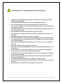
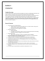
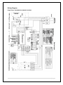
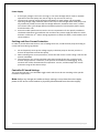
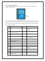
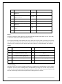
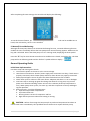
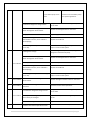
Enviro-tex Domestic EVI Series - Air Source Heat Pumps
Installation and Users Guide
IMPORTANT SAFETY INSTRUCTIONS
READ AND FOLLOW ALL INSTRUCTIONS
RETAIN THIS GUIDE FOR FUTURE REFERENCE
1|Page
Enviro-Tex Domestic EVI Series
Installation and User Guide
Customer Service
If you have any questions about ordering Air Source Heat Pump replacement parts and products,
please get in touch.
Customer Service and Technical Support
(Open from 9am-4pm Monday- Friday)
Phone: 01472 828086
Email: [email protected]
Address: 169-177 Cleethorpe Road, Grimsby, DN31 3AX
Website:
www.enviro-tex.co.uk
2|Page
Table of Contents
IMPORTANT SAFETY PRECAUTIONS............................................................................................... 5
Health and Safety (Materials)................................................................................................... 5
Important End User Safety Information................................................................................... 7
Section 1........................................................................................................................... 8
Introduction................................................................................................................................... 8
Product Overview..................................................................................................................... 8
General Features....................................................................................................................... 8
Section 2........................................................................................................................... 9
Installation..................................................................................................................................... 9
Materials needed for installation.............................................................................................. 9
Installation of Outdoor Unit.................................................................................................... 10
Suggested Installation Methods............................................................................................. 11
Water Connections................................................................................................................. 14
Plumbing Installation Requirements....................................................................................... 14
Electrical Connections............................................................................................................. 15
General Information............................................................................................................... 15
Electrical Wiring Diagram........................................................................................................ 16
Power Supply.......................................................................................................................... 17
Grounding and Over Current Protection................................................................................ 17
Controller PC Board Setting.................................................................................................... 17
3|Page
Section 3......................................................................................................................... 18
Operating Heat Pump................................................................................................................... 18
LCD User-Friendly Interface Controller................................................................................... 18
General Instruction................................................................................................................. 18
Controller Panel...................................................................................................................... 18
Controller Set-up.....................................................................................................................19
1.
2.
3.
4.
5.
Temperature Setting........................................................................................................ 19
System Status Display Value............................................................................................. 20
Clock Setting..................................................................................................................... 21
Timer Setting.................................................................................................................... 22
Manual/Forced Defrosting............................................................................................... 23
General Operating Guide..................................................................................................................... 23
Users Guide.......................................................................................................................................... 24
Product Protection............................................................................................................................... 24
Section 4......................................................................................................................... 26
General Maintenance.................................................................................................................. 26
Controller Error Codes........................................................................................................... 26
Inspection and Service........................................................................................................... 27
Owner Inspection................................................................................................................... 27
Trouble Shooting.................................................................................................................... 27
Problems and Corrective Action............................................................................................. 28
Section 5......................................................................................................................... 35
Components Assembly................................................................................................................. 35
4|Page
-------------------------------------------------------------------
HEALTH AND SAFETY INFORMATION
-----------------------------------------------------------------INFORMATION FOR INSTALLER AND SERVICE ENGINEERS
Under the Consumer Protection Act 1987 and the Health and Safety at Work Act 1974, it is required
to provide information on substances hazardous to health (COSHH Regulations 1998).
Enviro-Tex takes every reasonable care to ensure that these products are designed and constructed
to meet these general safety requirements, provided they are properly installed and used.
To fulfil this requirement, products are comprehensively tested and examined before dispatch.
When working on the appliance, it is the responsibility of the user/engineer to ensure that any
necessary personal protective clothing or equipment is worn when appropriate for parts, which
could be considered hazardous or harmful.
This appliance may contain some of the items below:
Refrigerants
The appliance contains R407c refrigerant. The constituents of R407c are HFC’s R125, R134a and R32,
all of which have low toxicity levels.
When handling, avoid inhalation and contact with the skin and eyes. Suitable personal protective
equipment (PPE) must be worn (gloves, overalls, eye protection) and a comprehensive first aid kit
(containing eyewash) should be easily available.
Site engineers should have a certificate of competence and should know and understand the
properties and hazards before handling liquid refrigerants.
When the appliance has come to the end of its life span, an approved engineer must dispose of the
equipment and refrigerants in accordance with the EU laws.
Seek urgent medical attention if in haled or digested. Exposure to eyes and skin should be followed
by immediate cleansing of the affected areas and medical attention if necessary.
Insulation
Fibre insulation may be irritating to the skin, eyes, nose and throat. When handling, avoid inhalation
and contact with the eyes. Use disposable gloves, facemasks and eye protection.
After handling, wash hands and other exposed parts. When disposing, reduce dust with water spray
and ensure all parts are securely wrapped.
Glue, Sealants and Paints
Glue, sealants and paints are used in this appliance and present no known hazards when used in the
manner of which they are intended.
5|Page
IMPORTANT SAFETY INFORMATION FOR THE END-USER
•
•
•
•
•
•
•
•
•
•
•
•
•
•
•
•
•
•
•
•
Installation of the appliance must only be carried out by persons with suitable
engineering qualifications.
Do not attempt to modify, repair or service the appliance yourself.
Do not insert body parts or any other items into the air inlet or outlet.
Do not start or stop the unit by removing the power cable; always use the controls
and switches provided.
If installed outside, ensure the appliance is protected from prolonged exposure to
large quantities of water.
Do not operate the unit or the programmer with wet fingers.
Upon replacement of the fuse, ensure an adequate replacement is used (e.g not
fuse wire)
Keep the programmer unit of out of reach of children.
The electrical supply must be isolated during a heightened risk of lightning strikes.
Do not attempt to move the appliance once it is installed; this must be carried out
by a qualified engineer.
Isolate the electrical supply to the appliance if an odour presents, or scorching is
detected.
Only use this appliance for the purpose intended.
Ensure the area around the appliance is clean, well-ventilated and kept free of all
obstructions.
Do not keep items on top of the appliance or use it to support other appliances.
Do not under any circumstances stand on the appliance.
Isolate the electrical supply to the appliance if it is to be switched off for a period
of more than two weeks.
Drain the water from the water circuit if power to the unit is to be switched off
during very cold weather.
Periodically check the condition of any supports for deterioration.
Do not wash the unit with water, alcohol, benzene, thinner, glass cleaner, polish or
powders.
During cleaning, isolate the electrical supply to the appliance.
6|Page
Section 1
Introduction
Product Overview
Air Source Heat Pumps transfer heat from the ambient air to water, providing high-temperature hot
water up to 60°C. The unique enviro-tex heat pump is widely used for house heating.
With our innovative & advanced technology, the EVI range of heat pumps can operate very well at
-25°C ambient temperature with high output temperatures up to 60°C, which ensures the
compatibility with normal sized radiator based systems without supplementation. Compared with
traditional oil/LPG boilers, Enviro-Tex high-temperature heat pump produces up to 50% less CO²
whilst saves up to 80% on running costs. Enviro-Tex heat pumps are not only highly efficient, but
also easy and safe to operate.
General Features
1. Low running costs and high efficiency.
• A high coefficient of performance (COP) of up to 5, results in lower running costs
compared with traditional ASHP technology.
• No immersion heater supplement is required.
2. Reduced Capital Costs.
• Simple installation
• Compatible with traditional radiator systems, eliminating the expense of installing
under floor heating or changing to oversized radiators.
3. High Comfort Levels.
• High storage temperature results in increased hot water availability.
4. No potential danger of any inflammable, gas poisoning, explosion, fire, electrical shock
which are associated with other heating systems.
5. A digital controller is incorporated to maintain the desired water temperature.
6. Long-life and corrosion resistant composite cabinet stands up to severe climates.
7. The latest EVI compressor ensures outstanding performance, ultra energy efficiency,
durability and quiet operation.
8. Self-diagnostic control panel monitors and troubleshoots heat pump operations to ensure
safe and reliable operations.
9. Intelligent digital controller with friendly user interface and blue LED back light.
10. Separate isolated electrical compartment prevents internal corrosion and extends heat
pump life.
11. The heat pump can operate down to ambient air temperature of -25°C.
7|Page
Section 2
Installation
The following general information describes how to install the air source heat pump.
Note: Before installing this product, read and follow all warning notices and instructions. Only a
qualified / competent person should install the heat pump.
Materials needed for Installation:
The following items are needed and are to be supplied by the installer for all heat pump
installations:
1. Plumping fittings.
2. Level surface for proper drainage.
3. Ensure that a suitable electrical supply cable is provided. See the rating plate on the heat
pump for electrical specifications. Please take a note of the specific current rating. No
junction box is needed at the heat pump; Connections are made inside of the heat pump
electrical compartment. Conduit may be attached directly to the heat pump jacket.
4. It is advised to use PVC conduit for the electrical supply cables.
5. Use a correctly sized water pump to obtain minimum water flow rate.
6. A filter on the water inlet is needed.
7. The plumbing should be insulated to reduce heat losses.
Note: We recommend installing shut-off valves on the inlet and outlet water connections for ease of
serviceability.
Enviro-tex EVI Series Air Source Heat Pump Specification
Model
Ambient
Temp.
(20°C)
Normal
Capacity
Power Input
COP
Ambient
Normal
Temp.
Capacity
(7°C)
Power Input
COP
Max Power Input
Power Supply
Rated Current
Rated Water Flow
Rated Water Temp.
Max Water Temp.
Refrigerant
Compressor
Net Weight
Dimensions
Water Connections:
Ambient Temp.
Noise
EVI10000
kW
kW
kW
kW
kW
V/Ph/Hz
A
m³/H
°C
°C
Kg
mm
°C
dB(A)
EVI14000
EVI17000
Water Outlet Temp at 35/45°C
10.1/9.5
14.2/13.3
17.1/16
2.45/2.5
4.1/3.8
7.9/7.2
3.3/3.5
4.2/3.78
11.3/10
4.14/4.4
4.1/3.7
14.1/13
2.28/2.5
3.7/3.5
3.68/3.65
3.0/3.3
3.9/4.4
3.7/3.4
3.7/3.3
5.4/5.8
6.25/6.9
220-240V/1/50
11.2
16
18.9
1.8
2.5
3
55
60
R407C
Copeland Scroll EVI
100
125
140
1110x400x75 800/400/1220
1000/430/1175
1”
1 ½”
-25~40
52
54
56
8|Page
Note: The above design and specifications are subject to change without prior notice for product
improvement. For detailed specifications of the units please refer to name plate on the units.
Correct installation is required to ensure safe operation. The requirements for Enviro-Tex heat
pumps include the following:
1. Appropriate site location and clearances.
2. Wiring to conform to 17th edition wiring regulations.
3. Adequate water flow.
This manual provides the information needed to meet these requirements. Review all application
and installation procedures completely before continuing the installation.
Installation of Outdoor Unit
The heat pump should be installed on a solid level base that can take the weight, preferably a
concrete foundation. If concrete slabs are used they must rest on asphalt or shingle.
The heat pump should not be positioned next to sensitive walls, for example, next to a bedroom.
Also ensure that the placement does not inconvenience the neighbours. The heat pumps must not
be placed so that recirculation of the outdoor air can occur; this causes lower output and impaired
efficiency.
Large amounts of condensation water as well as melted waters from
defrosting can be produced. Condensation water must be led off to a
drain or similar.
The outdoor unit should be installed in a ventilated place, with enough
space for air inlet and outlet, while without thermal radiation or other
heat source. The air outlet should not be against the wind.
Generally, horizontal air flow type heat pump does not need sheltering.
The structure design has protected all internal components against rain
and sunshine. A shelter is necessary to avoid snow burying the heat
pump in heavy snow areas.
9|Page
Please make sure the standardized voltage 220V-240V is available to the heat pump, otherwise the
performance would be influenced and could affect your warranty.
The foundation of the heat pump can be a cement or steel structure. Anti-vibration rubber feet and
a flat foundation are generally required. The foundation structure can be flexibly designed according
to the working weight of the heat pump. (Please see the technical data in this manual.)
Water drainage should be available near the installation location for draining water in an effective
way. Do not install the heat pump in a place where there is polluting or corrosive materials like oil,
flammable and explosive gas and sulphide ect. Keep it far away from sands, falling leaves and area
with high-frequency equipment.
Installation on a balcony or on a roof-top must be in accordance with the allowable stress of the
building structure.
The installation space should be referred as follows:
Intake and outlet should not be obstructed. The wall the unit is to be mounted on should be strong
enough to bear the weight and vibrations of the unit.
Allow for proper clearances around the unit. Location should allow easy access for maintenance.
For any further guidance on heat pump installations for planning purposes, please consult the latest
version of the MCS guidelines or your local authority.
10 | P a g e
Suggested Installation Methods
1. For heating and hot water (See figure 2)
Control principal:
1) 3-way valve: For domestic hot water mode, 3-way valve powers on. For heating, 3-way valve
powers off.
2) When both heating and domestic hot water don’t reach the set temperature, hot water is
prioritized.
3) When domestic hot water reaches the setting temperature, the system shifts the 3-way
valve automatically to heating mode if there is a call for heat from the switching contact.
When the in-built temperature sensor on the return pipe (A6) reaches the setting
temperature L3, the system goes into standby until this temperature drops. Or when the
switched contact signal is satisfied, whichever occurs first.
Notice: a) The switched contact should connect to a room thermostat or external controls.
b) The hot water tank with coil for domestic hot water should ideally be specially designed
for use with a heat pump, with the heat exchange capacity of the coil larger than the
maximum output of the heat pump. – Enviro-tex can supply this if required, please contact
us for details.
c) The circulation pump should be properly sized to ensure the flow rate in the system meets
the minimum required by the unit. Its actual water flow cannot be less than water flow on
name plate.
(Figure 2)
11 | P a g e
2. For hot water only / buffer tank or thermal store installations, with or without a coil. (See
Figure 3)
1) Set L3= 20°C, short connect the terminals 1 to 3 of switch contact.
2) Terminal for 3-way valve is not needed.
The system will now be controlled by the programmer supplied and the thermostat probe only.
(Figure 3)
3. For direct heating only installation with external controls (See Figure 4)
1) Set the water tank temperature = 20°C, install the water tank temperature sensor into the return
pipe of the heat pump.
2) According to site requirements, set return water temperature L3 of the heating system.
3) Terminals of 1-3 connect to the switched signal of room thermostat or external controls.
The terminal of 3-way valve is not needed.
4) The circulation pump should be properly sized to ensure the flow rate in the system meets the
minimum required by the unit. Its actual water flow cannot be less than water flow on name
plate.
12 | P a g e
(Figure 4)
Water Connections
Water connections at the heat pump
Flexible pipe fittings are recommended to be installed on the flow and return connections. (See
Figure 3).
(Figure 5)
The water inlet and outlet connections to the heat pump, accept standard BSP threaded fittings.
CAUTION – Make sure that water flow rates can be maintained with the installation of
additional heat pumps and plumbing restrictions.
13 | P a g e
Plumbing Installation Requirements
1. Water pressure should not exceed 3 Bar.
2. Each part connected to the unit needs to be connected with method of loose jointing and
installed with intermediate valves.
3. Ensure that all plumbing has been properly flushed and tested.
4. All pipelines and pipe fittings must be insulated to prevent heat losses.
5. Install a drain valve at the lowest point of the system to enable the system to be drained
fully.
6. Install a check valve on the water outlet connection in back siphoning could occur.
7. In order to reduce the back pressure, the pipes should be installed horizontally.
8. Install an automatic bypass valve when connecting directly to a system (no buffer).
14 | P a g e
Electrical Connections
WARNING – Risk of electrical shock or electrocution.
Ensure that all high voltage circuits are disconnected before commencing heat pump installation.
Contact with these circuits could result in death or serious injury to users, installers or others.
CAUTION – Label all wires prior to disconnection when servicing the heat pump. Wiring errors
can cause improper and dangerous operation. Check and ensure proper operation after servicing.
General Information
Wiring connections must be done according to the wiring diagram found on the inside of the heat
pump access panel or see addendum A for reference.
The heat pumps must also be earthed. A ground lug is provided on the inside of the heat pump
electrical compartment.
The supplied controller is pre-wired using a low voltage low loss cable and can be easily moved and
located where required.
The controller plugs directly onto the cable supplied with no additional wiring required.
If you wish to extend this cable or any of the sensor cables, please use a shielded low loss cable.
15 | P a g e
Wiring Diagram
Single Phase: EVI10000/ EVI14000/ EVI17000
16 | P a g e
Power Supply
1. If the supply voltage is too low or too high, it can cause damage and/or result in unstable
operation of the heat pump unit, due to high in rush currents on start up.
2. The minimum starting voltage should be above 90% of rated voltage. The acceptable
operating voltage range should be within ±10% of the rated voltage. When heat pump units
are installed in parallel, ensure that the voltage difference, between these units, is within
±2% of each other. The voltage difference between phases of a three phase power supply
should be within ±2%.
3. Ensure the cable specifications meet the correct requirements for the specific installation.
The distance between the installation site and the mains power supply will affect the cable
thickness. Follow the 17th edition wiring regulations to select the cables, circuit breakers and
circuit breakers.
Earthing and Over Current Protection
In order to prevent electrical shock in case of leakage from unit, install the heat pump according to
current electrical wiring regulations.
1. Do not frequently interrupt the voltage supply to the heat pump as this may result in a
shorter life expectance of the heat pump.
2. When installing over current protection, ensure that the correct current rating is met for this
specific installation.
3. The compressor, fan coil unit and heat pump water pump all have AC- contactors and
thermo relay protection. Therefore, in the process of installation and debugging, firstly
measure each of the aforementioned components’ current, and then adjust the current
protection range of the thermo relays.
Controller PC board Settings
The Controller PCB has a pin selectable toggle switch which must be set according to the specific
installation requirement.
Note: Before any changes are made to the pin settings, ensure that the mains supply
power is OFF at the circuit breaker or physically disconnected from the mains supply.
17 | P a g e
Section 3
Operating Your Heat Pump
LCD User-Friendly Interface Controller
General Instructions
The operation panel features:
1. Capacitive touch keys for higher operating sensitivity and unlimited key operations.
2. Minimal electromagnetic susceptibility and interference.
3. Stylish appearance of easy viewing purposes.
4. Dust and Water Proof.
5. Install on wall indoor for convenient operation.
6. Automatic Key Lock Function (AKL).
Controller Panel
Operating Controller
Operation Guide
When the power supply to the heat pump is switched on for the first time, an audible tone is heard
from the controller. The LCD will be displayed in a dimming mode (no back light). At this time the
touch keys are locked (see “lock key display” symbol).
18 | P a g e
Keys Explanation:
Unlocking Keys: Press the “power” key for 3 seconds until you hear the audible tone, then release
the key. The backlight of the LCD display will turn on and the key pad is locked with no “lock key
display” symbol. The key pad will automatically lock after 60 seconds, displaying the “lock key
display” symbol.
“Power” keys: By pressing the “power” key, the unit can be switched ON and OFF.
“▲” and “▼” keys: Press to increase and decrease values.
“Setting” key: Press for inquiry, parameter and password setting.
“Timer” key: Press for timer setting, timer eliminate and clock settings.
Controller Set-Up
1. Temperature Setting:
Make sure key-pad is unlocked. Press the “▲” key, “temperature setting” symbol is flashing and
the set temperature is displayed. Press the “▲” key again, the displayed temperature will
increase. Press the “▼” key, “temperature setting” symbol is flashing and the set temperature is
displayed. Press the “▼” key again, the displayed temperature will decrease. The range of water
temperature can be set from 20°C (68°F) to 60°C (140°F) (default = 60°C (140°F)).
NOTE:
•
It is recommended that the maximum setting temperature to 60°C
19 | P a g e
2. System Status display values:
Make sure key-pad is unlocked. Press the “setting” key and enter into the inquiry panel with
“inquire” symbol on display.
On the state of power on, press the “setting” key for more than 3 seconds, until an audible tone is
heard and enter into the setting panel with “setting” symbol on display. After parameter set, press
the “setting” key again for next parameter setting, after all parameters set, exit the setting panel.
Details are shown as follows:
Code Name
Range
Default
Water tank temperature setting
20℃─60℃
55, Change to 20 for no
domestic hot water function
(Method 3.)
L1
Temperature difference between
hot water and indication
0℃─15℃
0
L2
Decreasing water temperature
difference to restart Compressor
3—18
4
L3
Inlet water temperature of heating
20℃─55℃
35, Set to 20 for no heating
function. (Method 2.)
L4
Maximal water tank temperature
30--99
55
L5
Ambient temperature to start
electric heating
0℃─35℃
7
L6
NO
NO
NO
L7
NO
NO
NO
L8
Compressor overload current
setting
0~33A
XX, (where 0 means no current
protection)
L9
NO
NO
NO
h1
Defrosting period
20─99min
40 min
h2
Ambient temperature to start
defrosting function
-15℃─1℃
-1℃
20 | P a g e
h3
Defrosting time
5-20min
8min
h4
Evaporator coil temperature to quit
defrosting
1℃─40℃
25℃
P1
Electronic expansion valve
regulation period
20~180 s
60
P2
Degree of super heat
-8~15°C
02
P3
Allowed discharge gas temperature
70~135°C
100
P4
Expansion valve opening degree in
defrosting
6~55°
55
P5
Expansion valve minimum opening
degree
6~30
15
P6
Super heat compensation
0~12
4
Note:
●If electric expansion valve (optional) is not controlled by controller (dial switch 3 in the “ON” side),
no indication shows of P1-P6 while parameter setting.
For a single heat pump system (SHPS), the inquiry codes are from A1 to A9. By pressing the “setting”
key sequentially, the desired inquiry code will be selected and value displayed. To exit the inquiry
panel, press the “setting” key once after the last inquiry code (Er) is reached. Details are shown as
follows:
Item
Info
Item
Info
A1
Evaporator coil pipe temp.
A6
Heating inlet water temp.
A2
Compressor suction temp.
A7
N/A
A3
Compressor discharging temp.
A8
Compressor current
A4
Ambient temp.
A9
EEV opening degree
A5
Water outlet temp.
Er
Error code
3. Clock Setting
Press the “timer” key for more than 8 seconds until an audible tone is heard and the “timer” symbol
disappears. The hour value is flashing and can be adjusted by pressing “▲” and “▼” keys. Press the
“timer” key for minute adjustment and repeat as previous. Press the “timer” key to exit. (Please note
that the clock setting can be used only when timer setting function is closed.)
21 | P a g e
4. Timer Setting
The heat pump consists of two separate timing functions. Timer 01 and 02 are used to set the
ON/OFF times of the heat pump within the 24 hour period. Timer 03 and 04 are used to set the
ON/OFF times of an external water pump within 24 hour period (Timer 03 and 04 - not
applicable with these models).
Heat pump ON/OFF timers:
01 – ON/OFF timing
02 – ON/OFF timing
External water pump ON/OFF timers:
03 – ON/OFF timing
04 – ON/OFF timing
Press the “timer” key and enter 01 ON time. Set the ON time as in Clock Setting section. Press the
“timer” key again to set timer 01 OFF time. Set the OFF time as in Clock Setting section. Repeat
sequence until all timer settings are completed.
If, however, a timer is not used, set ON and OFF times to 00:00. Timer setting can be randomly
selected. For example, Timer 01 ON, Timer 02 OFF, Timer 03 OFF and Timer 04 OFF.
22 | P a g e
After completing all timer settings, the controller will display the following:
To cancel the timer feature, press the “timer” key for more than 3 seconds until an audible tone is
heard, then release key, timer is now cancelled.
5. Manual/ Forced Defrosting:
Although this heat pump features an automatic defrosting function, a manual defrosting function
enables the user to manually defrost the heat pump when unusual frosting appears. Make sure the
key-pad is unlocked. Ensure that heat pump unit is in running mode, displaying the heat symbol.
Press the “▼” key for more than 8 seconds until an audible tone is heard, and release key. The heat
pump will be in defrosting mode and the “defrost” symbol will be on display --
.
General Operating Guide
Initial Start-Up Precautions
First boot-strap and running state checks.
1. To ensure the power to the unit is at the correct voltage.
2. Unit Electrical connections: Check if power supply wire connections are okay; if earth wire is
properly connected; check if water pump and other chain devices are properly connected.
3. Water pipe and pipes: ensure all pipes have been flushed and are free of debris.
4. Check water system: make sure the water flow is adequate and there is no air or leakages.
5. First boot-strap or starting up again after being shut down for a long time, stop, ensure
power is on ahead and heating at least 12 hours for crankcase (local loop temperature is
zero). Water pump starts up first, fan starts up, and then compressor starts up and begins
regular operation.
6. Running checks: check the following items:
a. Input and output water temperature.
b. Cycle water flow rate.
c. Running electric current of compressor and fan.
d. High and low pressure value when heating is running.
CAUTION – Refrain from using this heat pump if any technical components have been in
contact with water. Immediately call a qualified service technician to inspect the heat pump.
23 | P a g e
CAUTION – Keep all objects clear from above the heat pump. Blocking air flow could
damage the unit and may void the warranty.
Users Guide
1. Rights and Responsibility
1.1 To ensure you have the service guarantee period, only qualified heating engineers can install and
repair the unit. If you infract this request and cause any loss and damage, our company will not be
held responsible. Please refer to your warranty card for further information.
2. User Guide
2.1 All safety protection devices are set in unit before leaving the factory, don’t adjust it by yourself.
2.2 Units have been charged with refrigerant and lubricating oil, if needed owing to a leak; please
refer to the charging quantity on nameplate.
2.3 The external water pump must be connected to the output from the unit.
2.4 Use antifreeze / glycol when the environment temperature is less than zero in winter.
2.5 Safety Precautions
a. Unit must be installed by a competent person, plumber or heating engineer.
b. Please check that power supply corresponds with unit size.
c. The main power switch of unit should have earth leakage protector; the power cable must
meet the unit power requirements.
d. Unit must have a ground wire; don’t use the unit if there is no ground wire.
e. Don’t use the unit if the fan fence has been removed.
f. To avoid electric shock or fire, don’t store or use, oil paint, petrol, combustible gas or
liquid around the unit; don’t throw water or other liquid on to the unit and don’t touch the
unit with wet hands.
g. Don’t adjust the switch, valve, controller or internal data without permission of customer
support team.
h. If a safety protection device is activated at start up, please contact the customer support
team.
Product Protection
1. Compressor Time Delay Protection: To ensure the compressor is protected, a time delay of 3
minutes is needed to restart the compressor.
2. Water Flow Switch Protection (error code: 03E): To ensure that the heat pump will not
operate during no water flow conditions and the error code will be displayed. – If no water flow
switch has been installed please link out terminals.
3. Compressor High Discharge Temperature Production (error code: 12E): If a high
compressor discharge temperature (≥ 115C (239F)) is detected for 30 seconds, the heating function
will be disabled and the error code will be displayed. The heat pump will resume operating
automatically after 3 minutes.
4. Compressor High Pressure Protection (error code: 05E): If a high pressure is detected on the
compressor, the heating function will be suspended, the error code will be displayed and the alarm
will sound. The heat pump unit will resume operation 3 minutes after the high pressure switch was
rest. If the same error code appears for 3 consecutive times within an hour the heating function will
be permanently disabled and the alarm will sound. Please consult an authorised service technician.
24 | P a g e
This error normally relates to an inadequate water flow rate causing the heat pump to overheat,
check the size of the pump and pipe work.
5. Compressor Low Pressure Protection (error code: 06E): If a low pressure is detected on the
compressor, the heating function will be suspended, the error code will be displayed and the alarm
will sound. The heat pump unit will resume operation 3 minutes after the high pressure switch was
rest. If the same error code appears for 3 consecutive times within an hour, the heating function will
be permanently disabled, the error code will be displayed and the alarm will sound. Please consult
an authorised service technician.
NOTE: Low pressure will not be detected under 2 circumstances, during the defrosting period
and/or during the first 5 minutes after the compressor has started.
6. Sensor (Any) Faults (error codes: 15E, 16E, 18E, 21E, 22E, 27E, 29E): When any sensor
appears to be faulty, the heating function will be suspended and the corresponding error code will
be displayed. The heat pump will resume operation when the fault has been corrected.
7. Frost Protection:
( 1 ) In standby mode, when the ambient temperature ≤ 5C, if the compressor stops for more than
10 minutes, the circulating pump starts to run 30 seconds. (Circulating pump runs 30 seconds every
10 minutes);
( 2 ) In the off mode, when the ambient temperature ≤ 5C, the water temperature ≥ 2C, the
circulating pump runs 30 seconds every 10 minutes, when the water temperature is ≤ 2C, the
starting system, until the water temperature is ≥ 12C system stops.
9. Water Pressure Switch Protection (error code: 31E): When the chilled water feeding
magnetic valve is open and the controller detects that the water switch is in the off position for a
period of six seconds, the heating functions will be suspended and the error code will be displayed.
The heat pump will automatically resume operation with a 3 minutes delay time after the water
pressure switch was reset.
10. Compressor over Current Protection (35E): This function will only be activated after 6
seconds after the compressor has started. When the current is equal to or higher than the set
current, L8 (refer to Parameter Setting in Section 3) for a consecutive period of 6 seconds, the
heating function will be suspended and the error code (35E) will be displayed. The heat pump will
resume operation when the fault has been corrected.
11. Controller Communication Faults (09E): There is some problem between control panel and
main PCB connection or control panel and PCB problem.
25 | P a g e
Section 4
General maintenance
Controller Error Codes
The following Common Error Codes for the heat pump units displayed on the controller:
CODE
NAME
CODE
NAME
01
Phase Failure
18
Abnormal compressor discharge temperature
and/or Faulty compressor discharge
temperature sensor
02
Phase Stagger
21
Ambient temperature too low and/or Faulty
ambient temperature sensor
03
Water flow switch
22
Faulty grounding heating inlet water sensor
05
Compressor high pressure and/or
faulty switch
25
Faulty water level detector
06
Compressor low pressure and/or
faulty switch
27
Faulty outlet water temp sensor
09
Controller communication
29
Faulty compressor suction temp sensor
11
Password protection
31
Faulty water pressure switch
12
Compressor high discharge
temperature
32
Outlet water temp. too low
15
Faulty inlet water tank water
temperature sensor
35
Compressor over current protection
16
Faulty Evaporator sensor
NOTE:
If a fault occurs during normal heat pump operation, a common error code will be
displayed on the controller display panel. Follow the instructions in Section 3, Controller SetUp, “System status display values (2)” to “inquire” (check) the specific error codes for the
corresponding heat pump systems.
26 | P a g e
Inspection and Service
Enviro-tex air source heat pumps are designed and built to provide long life and performance,
when installed and operated properly under normal conditions. Periodic inspections are
important to keep your heat pump running safely and efficiently.
Owner Inspection
Enviro-tex recommends that inspections on heat pumps are done frequently, especially
after abnormal weather conditions. The following basic guidelines are suggested for your
inspection:
1.
Make sure the front of the unit is accessible for service.
2.
Keep the top and surrounding areas of the heat pump clear of all debris.
3.
Keep all plants and shrubs trimmed and away from the heat pump especially the area
around the fan.
4.
Keep lawn sprinklers from spraying on the heat pump to prevent corrosion and damage.
5.
Ensure that the earth wire is always properly connected.
6.
A w a t e r filter must be i n s t a l l e d a n d maintained.
7. All the safety protection devices have been set up; please refrain from changing these
settings. If any changes are needed, please contact our support team.
8. If the heat pump is installed under roof without a gutter, ensure that all measures are
taken to prevent excessive water from entering the unit.
9. Do not use this heat pump if any electrical part has been in contact with water.
Contact an authorized service technician.
Troubleshooting
Use the following troubleshooting information to resolve issues with your heat pump.
WARNING — RISK OF ELECTRICAL SHOCK OR ELECTROCUTION.
Ensure that all high voltage circuits are disconnected before commencing heat
pump installation maintenance. Contact with these circuits could result in
death or serious injury to users, installers or others.
•
Keep your hands and hair clear of the fan blades to avoid injury.
•
DO NOT attempt to adjust or service the unit without consulting your authorized
installer/agent.
•
PLEASE read the complete Installation and/or User’s Guide before attempting to operate
service or adjust the heater.
27 | P a g e
Problem and Corrective Action
NO.
Problem
Description
Possible Cause
Corrective Action
1. Ensure that incoming phase rotation is correct. Use a phase
rotation meter to check incoming phase.
1
Error code 01
or 02
1. Absent phase or phase
rotation or voltage imbalance
among the 3 phases
2. Test for absent phase, make sure that the circuit breakers
are switched ON and check cable connection.
3. Test for Voltage imbalance, if not balanced, check cabling
and connections.
2. Controller or PC Board
Faulty (Phase rotation
Protection damaged)
Replace the PC Board and/or Controller
Replace Water Flow Switch
1. Water Flow Switch Faulty
2
Error code 03
2. Connection cable damaged
or disconnected.
Replace the connection cable or reconnect the cable.
3. Controller or PC Board
Faulty
Replace the PC Board and/or the Controller.
1. Measured water tank water
Temp < Actual water tank
water Temp
3
Error code 05
If no flow switch installed, check flow switch terminal has been
linked out.
a) The water tank water
temperature sensor and PC Board
are not compatible.
Use the correct sensor.
b) The water tank temperature
sensor is not in the correct position.
Position the sensor
correctly.
2. The Y shaped filter is blocked.
Clean the filter.
3. The plumbing is blocked.
Repair or replace the plumbing and/or valves.
4. Too much air in the plumbing result in
reduction in flow rate.
5. Circulation pump faulty.
1. Remove air from the system.
2. Make sure that the circulation pump is working
correctly.
a) Circulation pump
damaged.
Repair or replace circulation
pump.
28 | P a g e
b) Circulation pump is too
small.
4
Error code 06
Install correct circulation pump
for specific application.
6. Excessive refrigerant charge volume.
Charge the correct volume of refrigerant specified
on the label.
7. Control cable of the high pressure
switch damaged or disconnected.
Replace the damaged cable or reconnect.
8. High pressure switch cannot be reset.
Replace high pressure switch.
9. Input of the high pressure sensor is
shorted with common, error code 05 is
still displaying.
Replace the PC Board.
10. The refrigeration system is blocked (by
ice or dirt).
Find the cause of blockage and replace the filter
and/or re-vacuum the system.
1. Refrigerant leakage.
Detect leakage and repair. Vacuum, charge
refrigerant and start heat pump.
2. Control cable of the high pressure
switch damaged or disconnected.
Replace the damaged cable or reconnect.
3. Low pressure switch cannot be reset.
Replace low pressure switch.
4. Input of the high pressure sensor is
shorted with common, error code 05E is
still displaying.
Replace the PC Board.
5. The refrigeration system is blocked (by
ice or dirt).
Find the cause of blockage and replace the filter
and/or re-vacuum the system.
5
Error Code 09
1. The controller cable damaged or
disconnected.
Replace damaged controller cable or reconnect.
6
Error Code 11
1. Incorrect installer/agent control
password.
Input the correct control password.
1. Insufficient refrigerant charge volume.
Charge the correct volume of refrigerant specified
on the label.
2. Compressor discharge temperature
sensor faulty or damaged.
Replace the compressor discharge temperature
sensor.
3. PC Board damaged.
Replace the PC Board.
1. Water tank water temperature sensor
Replace water tank water temperature sensor.
7
8
Error Code 12
Error Code 15
29 | P a g e
damaged.
9
10
11
12
13
Error Code 16
Error code 18
Error code 21
Error code 22
Error code 27
2. Water tank water temperature sensor
connector (plug) disconnected and/or
oxidized due to damp or water.
Reconnect or clean water tank water temperature
sensor.
3. The controller and/or PC Board faulty or
damaged.
Replace the controller or PC Board.
1. Defrost temperature sensor faulty or
damaged.
Replace the defrost temperature sensor.
2. Defrost temperature sensor connector
(plug) disconnected and/or oxidized due
to damp or water.
Reconnect or clean defrost temperature sensor.
3. The controller and/or PC Board faulty or
damaged.
Replace the controller or PC Board.
1. Compressor discharge temperature
sensor faulty or damaged.
Replace the compressor discharge temperature
sensor.
2. Compressor discharge temperature
sensor connector (plug) disconnected
and/or oxidized due to damp or water.
Reconnect or clean compressor discharge
temperature sensor.
3. The controller and/or PC Board faulty or
damaged.
Replace the controller or PC Board.
1. Ambient temperature sensor faulty or
damaged.
Replace the Ambient temperature sensor.
2. Ambient temperature sensor connector
(plug) disconnected and/or oxidized due
to damp or water.
Reconnect or clean Ambient temperature sensor.
3. The controller and/or PC Board faulty or
damaged.
Replace the controller or PC Board.
1. Return water temperature sensor faulty
or damaged.
Replace the return water temperature sensor.
2. Return water temperature sensor
connector (plug) disconnected and/or
oxidized due to damp or water.
Reconnect or clean Return water temperature
sensor.
3. The controller and/or PC Board faulty or
damaged.
Replace the controller or PC Board.
1. Outlet water temperature sensor faulty
or damaged.
Replace the outlet water temperature sensor.
30 | P a g e
14
15
Error code 29
Error code 31
2. Outlet water temperature sensor
connector (plug) disconnected and/or
oxidized due to damp or water.
Reconnect or clean outlet water temperature
sensor.
3. The controller and/or PC Board faulty or
damaged.
Replace the controller or PC Board.
1. Compressor suction temperature
sensor faulty or damaged.
Replace the Compressor suction temperature
sensor.
2. Compressor suction temperature
sensor connector (plug) disconnected
and/or oxidized due to damp or water.
Reconnect or clean compressor suction
temperature sensor.
3. The controller and/or PC Board faulty or
damaged.
Replace the controller or PC Board.
1. Water pressure switch connector (plug)
disconnected and/or oxidized due to
damp or water.
Reconnect or clean water pressure cable
connection to PC Board.
2. Water pressure switch cable damaged.
Replace the cable
3. The controller and/or PC Board faulty or
damaged.
Replace the controller or PC Board.
1. Check if the incoming voltage.
16
Error code 35
1. Compressor over current
2. Check if the compressor is overloaded.
1. Check whether the thermal relay is damaged, if
so, replace.
17
The heat
pump is not
heating
1. User's incorrect
operation and/or
parameter
settings.
a) The water tank water
temperature setting is set too
low and the desired
temperature cannot be reached.
Re-set the water tank water
temperature to the correct range.
b) The difference between the
required water tank water
temperature and the heat pump
restart temperature (L2) is too
big.
Re-set by reducing the value of L2.
c) Timer function has been set
to a specific ON and OFF time,
which does not allow sufficient
time for the heat pump to
operate.
Re-set the timer.
d) No electrical power supply to
the heat pump (no display on
the controller).
1. Check and ensure that circuit
breakers are ON.
2. Test voltage on the PC Board L/N/E
31 | P a g e
Connectors.
3. If power is not restored, replace
cable.
2. Problem with
controller or PC
Board.
a) The temperature displayed is
more than 45°C.
Check the water tank water
temperature sensor, replace if faulty.
b) PC Board is damaged due to
burnt relays.
Find out the cause, find faulty relay(s)
and replace.
c) PC Board microcontroller chip
faulty.
Replace the PC Board.
1. Insufficient refrigerant.
1. Check for leakages, if found, repair and recharge refrigerant as per volume specification on
label.
2. If no leakage was found, re-charge refrigerant as
per volume specification on label.
18
Slow increase
of water tank
water
temperature
2. The heating capacity of the heat pump
is insufficient.
Increase the size or number of heat pump units.
3. Serious residues/dirt occurred on the
heat exchanger.
Clean the heat exchangers.
4. The evaporator coil is dirty or jammed
and this will affect the heat exchange
efficiency.
Clean the evaporator coil.
5. The length of the pipes is too long
and/or improperly insulated.
19
20
The controller
displays ''00''
No display on
the controller
1. If the length of the pipes cannot be reduced,
then ensure well insulated piping.
2. Increase the size and number of heat pump
units.
1. The controller cable damaged or
disconnected.
Reconnect or replace controller cable and wrap it
with insulation tape.
2. PC board damaged.
Replace PC Board.
3. Pool temperature sensor and/or cable
disconnected or damaged.
Reconnect or replace pool temperature sensor.
1. Mains power supply is abnormal.
a) The main power supply
cables is disconnected or
damaged.
Reconnect or
replace the mains
power supply
cable.
32 | P a g e
Check and ensure
that the mains
power supply
cable', length and
thickness, is within
the specifications.
b) The main power supply
voltage is lower than 175V.
21
22
The fan does
not operate
The
compressor
does not
operate while
the fan is
working
2. PC board power cable is disconnected
or the fuse is burnt.
Reconnect PC Board cable or replace the fuse.
3. PC Board transformer is damaged.
Replace the PC Board transformer.
4. The controller cable damaged or
disconnected.
Reconnect or replace controller cable.
5. PC Board damaged.
Replace the PC board.
1. Fan motor capacitor damaged (under
this circumstance the fan motor will
overheat).
Replace fan motor capacitor.
2. The motor windings have been burnt.
Repair or replace the fan motor.
3. The display is ON but heat pump unit is
not in running mode/ON.
Press the power button and turn On the heat
pump unit.
4. Fan motor relay damaged.
Check and replace if damaged.
5. No fan motor output from PC Board.
Replace PC board.
6. Fan motor cable disconnected or
damaged.
Reconnect or replace fan motor cable.
1. Compressor damaged (under this
circumstance the compressor motor will
overheat).
Replace compressor capacitor.
2. Compressor connecting cable is burnt.
Replace compressor connecting cable.
3. The compressor windings have been
burnt.
Repair or replace the compressor.
4. The compressor is jammed or blocked.
Repair or replace the compressor.
5. AC contactor does not work.
a) The AC contactor
winding is damaged or
the contactor is jammed
and cannot close.
Replace the AC
contactor.
33 | P a g e
b) The main power
supply voltage is lower
than 175V.
Check and ensure that
the mains power
supply cable', length
and thickness, is within
the specifications.
c) No compressor relay
output from the PC
Board.
Check and/or replace
compressor relay or PC
Board.
6. Thermal relay damaged.
Replace the thermal relay.
1. Fan is not working.
Refer to "problem description #22".
1. Find the cause of blockage and replace the filter
and/or re-vacuum the system.
2. Insufficient refrigerant or the
refrigeration system is blocked.
2. Check for leakages, if found, repair and recharge refrigerant as per volume specification on
label.
3. If no leakage was found, re-charge refrigerant as
per volume specification on label.
23
Frost or ice
3. The defrost parameter is not set
correctly.
Re-set the defrost parameter to the correct value.
4. The defrost sensor is not placed
correctly.
Move the defrost sensor to the correct position.
5. The 4-way valve cannot be reversed
Check the 4-way valve to find the cause, replace
the winding or the 4-way valve.
6. Controller is damaged.
Replace the controller.
7. The refrigeration system has a problem.
Check and repair refrigeration system.
34 | P a g e
Section 5
Components assembly
EVI10000
ITEM
DISCRIPTION
QTY
ITEM
DESCRIPTION
QTY
1
Bottom Support Bar
2
16
Expansion Valve
2
2
Base Plate
1
17
Filter 1
1
3
Evaporator
1
18
Filter 2
1
4
Upright Support Bar
4
19
Filter 3
1
5
Water pump
1
20
Electrical Compartment
1
6
Compressor
1
21
Back right side Panel
1
7
Liquid and Gas Separator
1
22
Back Net
1
8
Heat Exchanger
1
23
Left Net
1
9
Liquid Receiver
1
24
Fan Cover
1
10
intermediate plate
1
25
Fan Net Guard
1
11
Fan Motor Guard
1
26
Front Panel
2
12
Fan Guard
1
27
Side Panel
2
13
Fan Blade
1
28
Right Panel
1
14
Four-way Valve
1
29
Top Panel
2
15
One-way Valve
1
35 | P a g e
EVI14000
ITEM
DESCRIPTION
QTY
ITEM
DESCRIPTION
QTY
1
Bottom Support Bar
2
15
Filter 2
1
2
Base Plate
1
16
Filter 3
2
3
Evaporator
1
17
Expansion Valve
1
4
Front Support Bar
2
18
One-way Valve
1
5
Back Support Bar
2
19
Four-way Valve
1
6
Water Pump
1
20
Electrical Compartment
1
7
Compressor
1
21
Fan Plate
1
8
Heat Exchanger
1
22
Fan Net Guard
2
9
Liquid and Gas Separator
1
23
Back Panel
1
10
Liquid Receiver
1
24
Right Panel
1
11
Fan Motor Guard
1
25
Top Panel
1
12
Fan Motor
1
26
Back Net
1
13
Fan
1
27
Side Net
1
14
Filter 1
1
28
Front Side Panel
1
36 | P a g e
Enviro-Tex
169-177 Cleethorpe Road,
Grimsby,
DN31 3AX.
Email: [email protected]
www.enviro-tex.co.uk
37 | P a g e