1
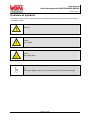
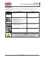
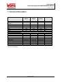
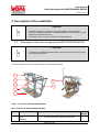
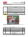
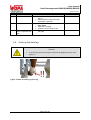
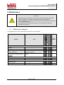
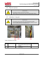
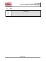
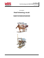
User Manual Hoof trimmingcrush:SA0018/SA0022/SA0026 Version: 24-09-14 User manual Hoof trimming crush SA0018/SA0022/SA0026 User manual Hoof trimmingcrush:SA0018/SA0022/SA0026 Version: 24-09-14 Manufacturer: Wopa Constructiebedrijf BV Rector Hulshofstraat 10 7135 JV Harreveld The Netherlands : : Email: Website: +31-(0)544 372415 +31-(0)544 372445 [email protected] www.wopa.com © Copyright 2014 No part of this publication may be reproduced, stored in a search system or transferred in any form whatsoever, either electronically or mechanically, or by photocopying or recording, or in any other way whatsoever without prior written consent from Wopa Constructiebedrijf BV (hereinafter in this manual also referred to as “Wopa”). Page 2 of 26 User manual Hoof trimmingcrush:SA0018/SA0022/SA0026 Version: 24-09-14 Introduction Wopa Constructiebedrijf BV specialises in development and manufacture of hoof trimming and treatment crushes for cows and bulls for professional users as well as for cattle farmers. Our crushes are developed and manufactured in the highest possible quality, according to the strictest requirements as far as safety, user convenience, animal welfare and hygiene are concerned, always striving for an optimum. This manual contains information and instructions relevant to installation, operation and maintenance of the machine. The machine is not suitable for use in explosive hazardous environments. All persons responsible for operation must, at minimum, read and comprehend the sections on operation and safety of these operating instructions. All persons responsible for assembly, installation, maintenance and/or repair must read and comprehend all these operating instructions. The user is responsible for interpretation and use of this manual under all conditions. Should you have any doubts or questions regarding the correct interpretation, please contact the owner or the supervisor. Keep this manual nearby the installation and within the users' reach. Keep a log of all major maintenance work, adaptations to the installations and observations, see Annex 8.1. Changes to the installation/machine are not permitted without prior written approval from the supplier. Contact the supplier for any special maintenance work not included in this manual. Comply with the safety requirements as given in Section 3 at all times. Proper functioning as well as the safety of the system can only be guaranteed if the recommended maintenance is carried out correctly and on time. Page 3 of 26 User manual Hoof trimmingcrush:SA0018/SA0022/SA0026 Version: 24-09-14 Warranty The warranty is subject to the following limitations. The warranty period for products supplied by Wopa is 12 months from the date on the purchasing document. The warranty is limited to production and material errors and therefore does not cover any breakdowns due to a part of the product exposed to any type of wear. Normal wear as can be expected from using this product is therefore excluded. 1. Wopa’s responsibility remains limited to replacing defective parts; we recognise no claims to any other type of loss or costs. 2. The warranty is automatically void in case of overdue or poorly implemented maintenance. 3. Should you have any doubts regarding maintenance work or should the machine fail to operate correctly, contact the supplier. 4. The warranty does not apply if the defect is the result of incorrect or negligent use or of maintenance carried out contrary to the instructions in this manual. 5. The warranty is void if any repairs or adaptations are made to the product by third parties. 6. Defects ensuing from damage or accidents caused by external factors are excluded from the warranty. 7. If we replace any parts in accordance with the obligations ensuing from this warranty, the parts we replaced become our property. Page 4 of 26 User manual Hoof trimmingcrush:SA0018/SA0022/SA0026 Version: 24-09-14 Table of Contents INTRODUCTION............................................................................................................................................... 3 WARRANTY ..................................................................................................................................................... 4 TABLE OF CONTENTS .................................................................................................................................... 5 EC CONFORMITY DECLARATION (COPY)...................................................................................................... 6 OVERVIEW OF SYMBOLS ............................................................................................................................... 7 PICTOGRAMS.................................................................................................................................................. 8 1. TECHNICAL INFORMATION..................................................................................................................... 9 2. DESCRIPTION OF THE INSTALLATION................................................................................................. 10 2.1. 2.2. 3. SAFETY .................................................................................................................................................. 14 3.1. 3.2. 3.3. 4. LOCATION ........................................................................................................................... 16 CONNECT THE MACHINE. ....................................................................................................... 17 PREPARING FOR TRANSPORTATION. ....................................................................................... 17 OPERATION ........................................................................................................................................... 18 5.1. 5.2. 5.3. 5.4. 6. GENERAL ............................................................................................................................ 14 DURING NORMAL USE ........................................................................................................... 15 OPERATING PERSONNEL ....................................................................................................... 15 INSTALLATION ...................................................................................................................................... 16 4.1. 4.2. 4.3. 5. DESCRIPTION OF THE MAIN COMPONENTS SA0018/SA0022/SA0026 ....................................... 10 ELECTRICAL INSTALLATION .................................................................................................... 12 STARTING UP....................................................................................................................... 18 EMERGENCY STOP. .............................................................................................................. 18 PRODUCTION....................................................................................................................... 19 HOOK UP THE FRONT LEG...................................................................................................... 20 MAINTENANCE ...................................................................................................................................... 21 6.1. 6.2. 6.3. 6.4. MAINTENANCE DIAGRAM ....................................................................................................... 21 CLEAN THE MACHINE. ........................................................................................................... 22 LUBRICATION OF REAR GATE ................................................................................................. 22 PARTS ................................................................................................................................ 23 7. DISPOSAL AS WASTE ........................................................................................................................... 24 8. APPENDIX .............................................................................................................................................. 25 8.1. LOGBOOK............................................................................................................................ 25 LIJST MET AFBEELDINGEN FIGURE 1: OVERVIEW SA0018/SA0022/SA0026 .................................................................................. 10 FIGURE 2: OVERVIEW OF THE ELECTRICAL INSTALLATION (THE TYPE OF HOOF TRIMMING CRUSH IN THE PHOTO MAY DIFFER FROM YOUR INSTALLATION). ......................................................................................... 12 FIGURE 3: LOCATION OF CRUSH ............................................................................................................ 16 FIGURE 4: DETAIL OF HOOKING UP FRONT LEG ........................................................................................ 20 FIGURE 5: LUBRICATION OF REAR GATE.................................................................................................. 22 Page 5 of 26 User manual Hoof trimmingcrush:SA0018/SA0022/SA0026 Version: 24-09-14 EC conformity declaration (copy) We, Wopa Constructiebedrijf BV Rector Hulshofstraat 10 7135 JV Harreveld The Netherlands : : Email: Website: +31-(0)544 372415 +31-(0)544 372445 [email protected] www.wopa.com declare, entirely under our own responsibility, that the product: machine : type: Hoof trimmingcrush SA0018/SA0022/SA0026 to which this declaration pertains, is consistent with the stipulations in Directives: 2006/42/EC 2004/108/EC (Machine Directive) (EMC Directive) the following standards were taken into account: NEN-EN-ISO 12100 NEN-EN 349 NEN-EN ISO 13849-1 NEN-EN 60204-1 Safety of machinery. Basic definitions, general design principles. Safety of machinery – Minimum gaps to avoid crushing of parts of the human body. Safety of machinery – Parts of the control systems with a safety function – Section 1: General design principles Safety of machinery – Electrical equipment of machines Section 1: General requirements The undersigned is authorised to compile the Technical Dossier: The Netherlands - Harreveld, September 2014 J.W.A. Wopereis Managing Director Page 6 of 26 User manual Hoof trimmingcrush:SA0018/SA0022/SA0026 Version: 24-09-14 Overview of symbols The following symbols are used for all actions that jeopardise the safety of the user and/or technician and require caution. Attention! Hazard: High voltage! Hazard: High temperature! Tip: Offers quick insight or tips to carry out certain actions more easily and simply. Page 7 of 26 User manual Hoof trimmingcrush:SA0018/SA0022/SA0026 Version: 24-09-14 Pictograms A number of pictograms and alerts are affixed to the installation to indicate possible risks to users, among other things. Pictogram Description Location Type plate On the machine frame Read the user manual Wear safety goggles when operating machine Wear hearing protection when operating machine. On the machine frame Warning pictograms for mechanical and electrical hazards On the machine frame Crushing hazard By the rear gate, if present. ATTENTION! Check regularly whether the pictograms and signs are still clearly recognisable and legible. Replace if this is no longer the case. Page 8 of 26 User manual Hoof trimmingcrush:SA0018/SA0022/SA0026 Version: 24-09-14 1. Technical information SA0018 SA0022 SA0026 - 10 to 40 - 10 to 40 - 10 to 40 < 75 < 75 < 75 dB(A) Machine dimensions Length Width Height Weight 2000 1000 2000 190 2000 1000 2000 215 2100 1000 2300 222 mm mm mm kg Maximum product dimensions Length Width Height Weight 2000 1000 2900 250 2000 1000 310 3000 1000 2900 317 mm mm mm kg Electrical connection (optional) Power supply National voltage Fuse required Connected load 1 phase / AC 230 4.9 0.75 1 phase / AC 230 4.9 0.75 1 phase / AC 230 4.9 0.75 V A kVA General Ambient temperature during operation Noise production 2900 * see electrical diagram Page 9 of 26 ˚C User manual Hoof trimmingcrush:SA0018/SA0022/SA0026 Version: 24-09-14 2. Description of the installation FUNCTION This section gives an overview of the most important components and functions. If detailed information is available elsewhere in the manual, you are referred to the specific sections. The design of your crush may differ from the figures below. 2.1. Description of the main components SA0018/SA0022/SA0026 FUNCTION The SA0018, SA0022 and SA0026 were developed especially for dairy cattle hoof trimming in the barn. The main components of the crush are shown in the illustration below: 1 2 6 3 7 4 5 Figure 1: Overview SA0018/SA0022/SA0026 Main components SA0018/SA0022/SA0026: Figure 1 Component 1a Front gate operating rope (SA0018) Description Pulling on the rope closes the front gate. The front gate can be opened at the front. Page 10 of 26 See Section User manual Hoof trimmingcrush:SA0018/SA0022/SA0026 Version: 24-09-14 Figure 1 Component Description 1b Front gate operating rope (SA0022/SA0026) 2 Manual hind leg winch 3 Manual belly strap winch 4 Rump chain (SA0018/SA0022) 5 Front leg support 6 Rump bar (SA0026) 7a Front gate (SA0018) 7b Front gate (SA0022/SA0026) Pulling on the rope closes the front gate. If one wants to open it, the front gate can be unlocked by pulling the rope upward and back at an angle and then opened by slackening the rope. After the strap is attached round the hind leg as shown in the photo above, the leg can be hoisted using the manual hoist so the hoof can be treated. As an option, this operation can be done with an electric motor Once the cow is moved into the crush, the belly strap is attached behind the front legs. The belly strap can be lifted using the manual hoist. As an option, this operation can be done with an electric motor. After the cow is moved into the crush, the rump chain is stretched tightly behind the animal and secured. The cow’s front leg can be secured to the front leg support with a rope so the leg can be treated. Optionally, the crush can be equipped with a front leg support with a winch. Another option is to equip it with a front leg support with electric winch. An alternative to the rump chain is the SA0026 equipped with a spring-loaded rump bar. After the cow has been moved into the crush, the rump bar is pressed tightly to the back of the animal and secured to the crush with a chain (if the chain is too loose the cow can sit on its haunches). The front gate can be closed with the operating rope. The front gate opens to the front. The front gate can be set to 3 positions using the operating rope: Entirely open: the cow can exit the crush at the front. Partially open: the cow can move its head through the front gate but not its shoulders. Stationary position. Closed: the front gate is closed behind the animal’s head. Page 11 of 26 See Section - 5.4 - - User manual Hoof trimmingcrush:SA0018/SA0022/SA0026 Version: 24-09-14 2.2. Electrical installation FUNCTION The electrical installation provides power to the electric winches and the sockets (as an option). See the electrical diagram in the switch box on the crush for the rest of the structure and controls of the electrical installation included in the delivery. The placement of the control components on your installation may differ from the photo below. ATTENTION! Work on the electrical installation can only be carried out by a technical expert. 3 4 1 5 2 Figure 2: Overview of the electrical installation (the type of hoof trimming crush in the photo may differ from your installation). The installation consists of the following components Figure 2 Component 1 Description To connect the machine to the power supply. 2 3 Power supply cable with plug Emergency stop Relay box 4 Control buttons The emergency stop switches off all operations. A relay box is installed for each drive. It contains the control components of the relevant drive. Each drive has 1 or 2 control panels to operate the following functions, depending on the version and/or the options available. o Front legs up/down Page 12 of 26 Section / location User manual Hoof trimmingcrush:SA0018/SA0022/SA0026 Version: 24-09-14 Figure 2 Component Description o o o Belly strap up/down Hind legs up/down Front legs and hind legs up/down Page 13 of 26 Section / location User manual Hoof trimmingcrush:SA0018/SA0022/SA0026 Version: 24-09-14 3. Safety 3.1. General The guarantee will lapse and no liability will be accepted in the event of damage caused by repairs and/or modifications not authorised by the supplier. In the event of faults please contact the supplier. The working area around the installation must be safe. The owner of the installation must take the necessary precautionary measures in order to operate the installation safely. Starting up the installation in an area with a risk of explosion is prohibited. The installation has been so designed that production is safe under normal ambient conditions. The owner of the installation must ensure that the instructions in this manual are followed in practice. The safety features provided must not be removed. Correct operation and safety of the system can only be guaranteed where maintenance is carried out correctly and in good time, as prescribed. Where work is to be carried out on the installation it must be disconnected from the power supply, the power supply must be locked off and the system must be depressurised. There is a risk of trapping when operating driven moving parts. It is the operator's responsibility to ensure that the installation is only started up when no parts of his own or other people's bodies are in the vicinity of the trapping zone. Only authorised persons appointed by the owner may carry out work on the electrical installation. Ensure by means of internal procedures and supervision that all applicable power supplies have been switched off. The installation must not be used during cleaning, inspection, repairs or maintenance, and must be disconnected from the electrical supply by means of the plug and/or the main switch. Welding work must not be carried out on the installation unless the cable connection to the electrical components has first been disconnected. The power supply to the control cabinet must not be used for the connection of machinery other than the hand tools provided for. Page 14 of 26 User manual Hoof trimmingcrush:SA0018/SA0022/SA0026 Version: 24-09-14 3.2. During normal use Check before commencing operations that no work is being carried out on the installation and that it is ready for use. Unauthorised persons must not enter the operational area of the installation. It is the operator's task to check this. 3.3. Operating personnel Operating personnel must be aged 18 or above. Only authorised persons may carry out work with or on the installation. Only work for which proper training has been received must be carried out. This applies both to maintenance activities and normal use. The operating personnel must be familiar with all potential situations, so that rapid and effective action can be taken in an emergency. Where a member of operational staff observes defects or risks or is not in agreement with the safety measures, this must be reported to the owner or the manager. Safety footwear is mandatory. Suitable work clothing is mandatory. All employees must observe the safety instructions to avoid presenting a risk to themselves and others. Comply strictly with the operating instructions at all times. Page 15 of 26 User manual Hoof trimmingcrush:SA0018/SA0022/SA0026 Version: 24-09-14 4. Installation EXPLANATION Consult the technical data and the circuit diagram provided for the correct specifications. 4.1. Location CAUTION The machine must be transported and installed upright. Place the machine on a level and stable substrate Take account of the instructions in Section 3 when carrying out any activity. Failure to follow these may lead to serious injury. 1 2 3 Figure 3: location of crush No. 1. What to do Install the anti-tipping bar 2. Slide out the front gate stops (SA0022/SA0026/SA0 039B). Action Slide the anti-tipping bar (Figure 3:3) into the recesses in the crush to increase lateral stability. The stops (Figure 3:1) are slid in for transportation. Press in the locking balls (Figure 3:2). Slide out the stops to allow maximal travel of the front gate. Page 16 of 26 Result User manual Hoof trimmingcrush:SA0018/SA0022/SA0026 Version: 24-09-14 4.2. Connect the machine. CAUTION Check that the voltage specified on the machine plate matches the mains supply. The machine must always be connected to an earthed socket to avoid the risk of fire or electric shocks (the earth connection is coded green/yellow). The electrical installation including the sockets must be connected in accordance with local regulations. The power cable must always be free and nothing must be placed on top of it. Replace the power cable immediately if it is damaged. 4.3. Preparing for transportation. CAUTION Preparing for transportation is the reverse procedure to making ready for use (see 4.1). With crushes equipped with an axle and drawbar it is essential that all locking mechanisms are correctly installed. Page 17 of 26 User manual Hoof trimmingcrush:SA0018/SA0022/SA0026 Version: 24-09-14 5. Operation CAUTION Take account of the instructions in Section 3 when carrying out any activity. Failure to follow these instructions may lead to serious injury. 5.1. Starting up No. 1. What to do Switch on the power. 2. Reset the emergency stop. Action Insert the plug in the socket. Pull out the emergency stop buttons. Result The control unit is now ready for use. 5.2. Emergency stop. CAUTION No. 1. The emergency stop button must always be pressed in in the event of an emergency. All motions will cease following operation of the emergency stop button. In order to take the machine back into use after an emergency stop the emergency stop button must first be reset. Before resetting the emergency stop button it must be ensured that restarting the moving parts of the machine will not lead to a hazardous situation. Reset the emergency stop What to do Reset the emergency stop button. Action Result The machine is now Reset the emergency stop button by pulling it out or rotating it (depending ready for use. on the type installed) so that it returns to its original position. Page 18 of 26 User manual Hoof trimmingcrush:SA0018/SA0022/SA0026 Version: 24-09-14 5.3. Production No. 1. 2. What to do Check that the crush is ready for use. Place the front gate ready. 3. Place the cow in the crush. 4. Attach the rump chain or rear gate. Action See Section 5.1. 5. Apply the belly belt 6. 7. Process a rear hoof. Process a front hoof. Result Open the front gate so that the head of the animal can pass through but not its withers. Lead the cow into the crush until its head has passed through the front gate. Close the front gate. Tighten the rump chain around the animal and secure it. (SA0018/SA0022) Lower the rear gate and secure it with the chain (SA0026). In order to avoid the risk of damage to the rear leg, ensure that the rear gate is pressed up tightly against the animal. Place the belly belt under the belly behind the front legs and tighten it. Where the (optional) electrical drive to the belly belt is present, the belt remains connected and is raised from the floor until it comes up under the belly. Place the belt around the rear leg and raise the leg. Process the rear hoof. Allow the leg to drop and release it. Pass the long, soft rope around the front leg below the dew claw and pull the leg up to the block. Wrap it around a couple of times and fasten the end to the hook on the side of the support. See 5.4 Where the front leg support is provided with a winch the front leg is hooked on as shown in 5.4. Turn the winch until the leg is fixed to the block, then run the short tension rope past the knee of the front leg and fasten it to the side of the front leg support using the hook. Process the front hoof. Release the short tension rope. Pull the pin on the side winch towards the hand grip with the index finger to release the rope. Unhook the rope. Page 19 of 26 User manual Hoof trimmingcrush:SA0018/SA0022/SA0026 Version: 24-09-14 No. 8. 9. 10. What to do Loosen the belly belt. Action Result Reverse the winch and loosen the belt, or: Allow the belt to drop to the floor (electrically, optional). Release the crush. Check that all ropes and belts have been freed. Open the front gate. Lead the cow out of the crush. Release the rump Release the rump chain or raise the chain or raise the rear rear gate. gate. 5.4. Hook up the front leg. CAUTION To avoid injury to the front leg the rope must be applied correctly. (see Figure 4) Figure 4: detail of hooking up front leg Page 20 of 26 User manual Hoof trimmingcrush:SA0018/SA0022/SA0026 Version: 24-09-14 6. Maintenance CAUTION! Always disconnect the machine from the power supply by pulling out the plug. Where a hydraulic accumulator is present this must be depressurised. Test the installation on completion of maintenance work or repairs to ensure that it can be used again safely. Only trained technical personnel may carry out the maintenance activities described or repair work. 6.1. Maintenance diagram Activity General Check on panic locks and hooks. Check ropes and chains. Check plugs, cables, controls and connections. Check that the left and right front leg ropes are hanging at equal lengths. Cleaning Clean the machine. Lubrication Grease nipples on rear gate sliding section. Other grease nipples. note Daily weekly Every 100 animals Annually Every 2 years The diagram below shows the maintenance activities to be carried out. See Section Renew where damage is visible. Renew where damage is visible. Alert a competent fitter where damage is visible. Where these are driven by a single motor. 6.2 Bearing grease. Bearing grease. Page 21 of 26 6.3 User manual Hoof trimmingcrush:SA0018/SA0022/SA0026 Version: 24-09-14 6.2. Clean the machine. EXPLANATION A high-pressure cleaner may be used for cleaning. Avoid bearings, winches and motors when cleaning with a high-pressure cleaner. Spraying in these areas may result in a sharp reduction in service life. 6.3. Lubrication of rear gate EXPLANATION The rear gate is slid out with the aid of gas springs fitted to the gate. To prevent grease entering the gas springs and causing damage, the gate must only be lubricated when it is fully drawn back. 1 2 3 Figure 5: lubrication of rear gate No. 1. 2. What to do Retract the rear gate. Grease the nipples. Action Attach the rear leg winch to the rear gate and tighten until the gate is fully retracted. Lubricate the rear gate nipples using a grease gun. Page 22 of 26 Result User manual Hoof trimmingcrush:SA0018/SA0022/SA0026 Version: 24-09-14 6.4. Parts EXPLANATION Consult the website at www.wopa.com for information on the available options and the parts available to order. Page 23 of 26 User manual Hoof trimmingcrush:SA0018/SA0022/SA0026 Version: 24-09-14 7. Disposal as waste Oil and components must not be disposed of as domestic waste. When replacing components or oil or at the end of the machines service life, ensure that all materials are collected and destroyed or reused in a legal and environmentally friendly manner. Page 24 of 26 User manual Hoof trimmingcrush:SA0018/SA0022/SA0026 Version: 24-09-14 8. Appendix 8.1. Logbook The logbook must include the following: The annual maintenance work Major replacements and any accidents Modifications Tests on emergency stop buttons and safety features Date: Carried out by: (authority, technician) Description: (nature of the activities, components replaced) Page 25 of 26 User manual Hoof trimmingcrush:SA0018/SA0022/SA0026 Version: 24-09-14 Date: Carried out by: (authority, technician) Description: (nature of the activities, components replaced) Page 26 of 26