1
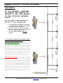
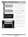
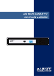
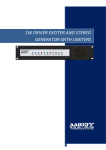
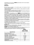
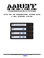
250W VHF FM TRANSMITTER SYSTEM WITH
4 WAY STACKED DIPOLE
AAREFF SYSTEMS LIMITED (UK) © 2013 - email [email protected] - web www.aareff.com
INTENDED USE
i.
The various pieces of equipment in this document are only for use permanently at a predefined location with a license or authorisation from the radio spectrum regulator of the EU
member state.
ii.
The installer must have competent RF engineering skills at their disposal, be EMC aware and
understand radio frequency systems. The final installation should be in accordance with the
site engineering document at http://www.aareff.com/ETR132.pdf . The radio station management
must assign a responsible person to the transmission equipment and installation.
PACKAGE CONTENTS
1 x STEREO CODER AUDIO LIMITER / 1 WATT FM DRIVER EXCITER 13.8V DC (ALSCB & 1WPLLB)
1 x DISTRIBUTION AMPLIFIER (4WDA19)
2 x 125W FM POWER AMPLIFIER (125WNTAP)
2 x DC LEAD TO DC LEAD (DC CONNECTIONS FROM ALSCB TO 1WPLLB TO DISTRIBUTION AMPLIFIER)
1 x MPX AUDIO LEAD (AUDIO CONNECTION FROM ALSCB TO 1WPLLB)
3 x BNC TO BNC LEAD (RF CONNECTION FROM 1WPLLB TO DISTRIBUTION AMPLIFIER TO 2 x 125WNTAP)
1 x 13.8V DC SWITCH MODE AC POWER SUPPLY (4.0 AMP)
3 x IEC AC CORD
12 x M6 SCREW, NUT AND WASHERS
2 x 19 INCH 3 x 2U CLAMPING BARS
2 x 2 WAY STACKED DIPLOE HIGH POWER ANTENNAS
2 x 50 METERS LMR400 CABLE WITH PLUGS FITTED
PRE-INSTALLATION
Before the transmitter and limiter can be used, it is necessary that the two tuned dipole antennas with
the LMR400 50 ohm coaxial cable are installed. Please ensure that all antenna connections are sound,
this is important as poor connections and soldered joints will cause severe noise to the transmission
and will use excessive RF bandwidth. IMPORTANT! PLEASE READ THE NEXT PAGE THOUGHLY
ABOUT THE ANTENNA SYSTEM.
SYSTEM SPECIFICATIONS
Power Supply
Power Amplifier RF Power Output
Freq Stability
Freq Range
Freq Adj. Accuracy
Deviation Sensitivity Stability
Spurious Emissions
Harmonic Emissions
RF Bandwidth
Output Connectors
RF Ruggedness
Audio Input Sensitivity
Audio Inputs Connector
Audio S/N Ratio
Audio Freq Response
Audio Distortion
Stereo Crosstalk
Pre-emphasis
Pilot Tone Freq
Pilot Tone Stability
Antenna Polarisation
Antenna Gain
Antenna Cable Loss
90-260 VAC 50/60 Hz
2 x 125 Watts (250 Watts Total) +/- 0.5 dB from -20 to +40 Deg C
Better than +/- 2 KHz from -20 to +40 Deg C, +/- 300 Hz typ.
100 KHz steps from 87.5 to 108 MHz
+/- 50 Hz
+/- 2 % max
Better than -75dB ref to carrier
Better than -70dB ref to carrier
200 KHz (+/-100 KHz @ -40 dB rtc)
SO239 (or optional N type)
Any VSWR, any phase, any length of time
0dBu 775 mV rms adjustable
Phono/ RCA socket
Better than 70 dB
30 Hz to 15 KHz +/- 0.5 dB
better than 0.1% at +/-75 KHz dev
35 dB
50 uS (75uS USA) or None
19 KHz
0.2 Hz
Vertical
+6 dB
-2 dB 50m LMR400 foam cable
AAREFF SYSTEMS LIMITED (UK) © 2013 - email [email protected] - web www.aareff.com
STACKED DIPOLE ANTENNA
! IMPORTANT ! PLEASE READ INSTRUCTIONS
The antenna is the most important part of the
transmission system and must be correctly installed
before proceeding further and before any
transmission equipment is connected.
Ideally this antenna should be mounted 20 meters high and clear of any surrounding objects to get
maximum range and more importantly to reduce risk of radio frequency radiation to personnel. When
mounted at 20 meters in height off ground and using 400 watts of transmitter power, power flux density
measurements made at ground level directly under the antenna show less than 1 W/m2. Several European
countries use a value for the power flux density of 10 W/m2 as a basis for considering whether or not an
area is safe. The issue of radio frequency radiation limits is a contentious one and work in this field
is continuing worldwide. Under no circumstances should the antenna be mounted and used at ground level
or within a few meters of personnel.
ANTENNA PACKAGE CONTENTS CHECKLIST
2 x Dipole (YELLOW marked cable + 53 cm RG59 cable)
1 x Dipole (RED marked cable + 53 cm RG59 cable)
8 x 65cm radiator rods
8 x Bolt, wing nut and plastic spacer
2 x RF connector 3 way junction box
4 x Mast fixing clamp
20 x Cable ties
2 x 50m Antenna Cable Phased Lengths
TO ERECT THIS ANTENNA YOU WILL NEED TO PROVIDE
1. PVC insulation tape and/or Self Amalgamating Tape
2. Tape Measure with mm
3. 10mm Spanner
4. A secure mounting mast with a diameter of 45-50mm and clear length of at least 8 meters for mounting
the dipoles to.
CONSTRUCTION
1.
Using the 8 x Bolt, wing nut and plastic spacer mount the two 65cm rods to each of the dipole
terminal boxes, make sure they are screwed tight.
2.
Mount the 4 dipoles to the mast using the clamps provided. It is IMPORTANT for correct
operation that the dimensions on the diagram are followed as closely as possible, all dipoles
must be directly above each other. A red dipole should be at the bottom, a yellow next up, a
red again next up and at the top a yellow dipole. ALL ‘TERMINAL BOXES’ MUST BE FACING THE
SAME WAY for the system to work properly and give maximum gain to the horizon.
3.
Mount one of the 3 way junction boxes between the red and the yellow dipole at the bottom.
Mount the other 3 way junction box between the red and the yellow dipole at the top.
4.
Connect the 2 x 50m phased LMR400 antenna cables to the centre of each of the two 3 way
junction boxes, MAKE SURE THE CONNECTORS ARE SCREWED PROPERLY AND TIGHT. Wrap PVC or selfamalgamating tape tightly around and all over the connectors to make them water resistant.
5.
IMPORTANT! DO NOT CUT BACK, ADD OR CHANGE THE ANY OF THE ANTENNA CABLE LENGTHS. To get
maximum radiation to the horizon it is important that the signal from each amplifier to each
dipole arrives at exactly the same time, this can only happen if the cables are exactly the
same length.
6.
Securely fix the 2 cables using PVC tape or large cable ties to the mast as shown in the
diagram. Make sure the cables are not going to flap around in the wind. Once again, do not
cut back any excess cable. To make the cabling look tidy, it is okay to coil the cable.
7.
Make sure that all fixings are tight and are not going to work loose over time with wind.
8.
On completion of the antenna installation you should have 2 x 50m cables ready to plug into
each of the large RF power amplifiers.
AAREFF SYSTEMS LIMITED (UK) © 2013 - email [email protected] - web www.aareff.com
STACKED DIPOLE ANTENNA
IMPORTANT!
DO NOT SHORTEN, LENGTHEN
OR CHANGE THE LENGTH IN
ANYWAY TO THE 50M LENGTHS
OF THE SUPPLIED ANTENNA
CABLE
FOR THIS SYSTEM TO WORK CORRECTLY AND
GIVE 1600 WATTS 1.6 KW ERP TO THE
HORIZON IT IS VERY IMPORTANT THAT:
1. THE ANTENNAS ARE MOUNTED STRAIGHT
IN A VERTICAL LINE WITH EACH OTHER
AS SHOWN IN THE DIAGRAM
2. THE RED DIPOLE IS AT THE BOTTOM,
NEXT UP YELLOW, NEXT UP RED AND AT
THE TOP THE YELLOW DIPOLE.
3. THE 50M CABLE LENGTHS ARE NOT
CHANGED
IF YOU NEED TO EXTEND THE ANTENNA CABLES
READ THE FOLLOWING CAREFULLY
THIS WILL WORK PERFECT! It is important that
the signals from the FM power amplifiers arrive at
each dipole at exactly the same time, this can
only happen if the LMR400 cables from each power
amplifier to each junction box are the exactly the
same length. It does not matter how long the
cables are, how many cables you use or how many
joins are used to connect the cables together. All
that matters is that the total lengths of cable
are exactly the same. In practice we have found
that a difference or tolerance of up to 2 cm
between each cables is acceptable, this gives a 2
to 3 degree tilt error up or down in the direction
of the horizon, any more than this and the loss of
signal to the horizon will become noticeable.
THIS WILL NOT WORK! If you choose to connect
any random lengths to extend the cables or lengths
that have not been properly and accurately
measured to be identical, then the signals will
arrive at the dipoles at different times and this
will cause a cancellation effect to the combined
signal in the air. In worst case the signal gain
to the horizon could disappear completely. In best
case some of the signal will be radiated, but it
will be very poor and inefficient. The only way to
measure the cables accurately is to lay them out
side by side on a flat road, side walk or similar.
With a person at each end, pull them tight and cut
them exactly equal with each other, then fit the
plugs. If you fit a plug incorrectly, you need to
repeat the process by cutting both again.
AAREFF SYSTEMS LIMITED (UK) © 2013 - email [email protected] - web www.aareff.com
BASIC CONNECTION SET UP
Arrange the units as shown in diagram to the
left. Use the supplied M6 screws, nuts, washers
and drilled bars to clamp the 2U 19 inch driver
and 2U 19 inch power amplifier. The power
amplifiers are much heavier, so these should be
at the bottom. The driver and distribution
amplifier are light and will suspend in the air
and do not need any support at the back.
Alternatively you can mount the units in a
professional 19 inch enclosure and integrate the
units with other equipment that you supply.
Arrange the units as shown in the picture above.
The picture shows the view of the rear panels.
It is self explanatory from the rear panel where
the power supplies plug in, DO NOT plug in
the power supplies at this stage.
1. Connect the output from each power amp to the
two 50m cables coming down from the dipole
antennas. If you find that the cables are longer
than necessary, DO NOT shorten these leads as
they are a specific phased length. It is okay to
coil and cable restrain them to make the
arrangement tidier.
2. Using the two leads supplied terminated with
BNC connectors connect the 1W input from each
power amp to the 1W driver outputs. You will
find that the supplied leads are longer than
necessary, DO NOT shorten these leads as they
are a specific phased length. It is okay to coil
and cable restrain them to make the arrangement
tidier.
3. There is a 15V DC adapter. Plug the adapter
into the ALSCB DC INPUT. Then connect the ALSCB
DC TO OTHER EQUIPMENT to 1WPLLB DC INPUT using
the short red and black DC cable. Then connect
the 1WPLLB DC AUX OUT to Distribution Amplifier
using the short red and black DC cable. Then
connect the AC mains power to the adapter.
4. Turn on the mains power to all units. The
driver will lock after a few seconds and power
amps should indicate power on the front panel
meters. The switch on the front panel of the
power amplifiers should be set to ‘FWD’
5. Provide an audio input to the ALSCB Stereo
Generator and Limiters and you are on air.
ALWAYS KEEP THE VENTS AND FANS CLEAR.
AAREFF SYSTEMS LIMITED (UK) © 2013 - email [email protected] - web www.aareff.com
REGULATORY ISSUES
EQUIPMENT COMPLIANCE
This system is:
i.
designed and tested to comply with the European Harmonised Standard for Telecommunications
ETS 300384 when used as shown in this document. It is generally considered and accepted that
harmonized standards reflect state of the art performance and a presumption of conformity.
ii.
designed to be compliant throughout its useful working life of typically 5 to 10 years.
iii.
not for use by the unqualified general market consumer.
iv.
specifically designed and only intended for installation by an engineer with other similar
apparatus in a fixed installation at a permanently pre-defined location.
ROHS
All components used in this apparatus are RoHS compliant and do not contain above the specified limits
in any of the following restricted substances:
-
Lead
Hexavalent Chromium
Mercury
Cadmium
Polybrominated Biphenyls (PBB’
Polybrominated Diphenylethers (PBDE’s)
PRODUCT END OF LIFE
This apparatus must NOT be disposed of with other domestic waste.
We are fully committed to maintaining our responsibilities to the environment. Owners of apparatus that
has reached the end of it’s useful life can return it to us for recycling, recondition, reuse or proper
disposal. You will be required to pay lowest cost postal service available to ship the apparatus to us.
Before shipping please contact us for more important information.
LEGAL ADVICE
It is the customer’s responsibility to check relevant laws, directives, regulations and licensing
requirements before putting this product into service with an antenna system. You, the customer agree to
defend, indemnify and hold harmless Aareff Systems Limited, it’s employees and agents, from and against
any claims, actions or demands, including without limitation legal and accounting fees, alleging or
resulting from improper or unlawful use of this product.
AAREFF SYSTEMS LIMITED (UK) © 2013 - email [email protected] - web www.aareff.com