1
3.2.3.2. Miscellaneous "Warts" Found
3.2.3.2.1. Atmel
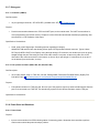
To use USB, the system designer is forced to under clock the microcontroller at 48MHz. It also doesn't have a real-time
clock (only a real-time timer). The Atmel chip was discarded early in the selection process because of USB issues (see
below).
3.2.3.2.2. Philips
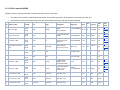
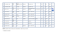
Philips was lacking in memory, and the quoted SRAM size of 40KB is deceptive. There is 32KB of SRAM for general use,
but 8KB of that is reserved for USB. That puts it on the lower limits of our memory requirements.
The Philips part exclusively uses an internal 1.8V voltage regulator, which means we can't hook up our switching power
supply. This increases the power consumption of the system.
Also, the pin multiplexing may prove troublesome. When PSAS designs a self-correcting rocket, all three PWMs will be
used on a node to control motor servos. The PWMs on the LPC2148 conflict with other devices we want to use, such as
SPI and UART0. However, this need is far in the future and we may switch to a new microcontroller before then.
3.2.3.2.3. STM
The STM part also requires the microcontroller to be run at 48MHz to use USB.
Another wart was that the ADC conversion time is listed as 1ms. This was unacceptable, considering that the other two
microcontrollers listed 2us conversion times. The PLL lock time also seemed to be a bit long; it was listed as 600us, while
Philips listed a 100us lock time. Further, the internal oscillator takes 2.5 seconds to start up. If the microcontroller has to
do a hard restart in flight, we would lose half of the apogee window to oscillator initialization.
Also, the data sheet was vague about whether the internal voltage regulator could be bypassed in Standby mode.
3.2.3.3. USB Considerations
The STM documentation for USB was severely lacking. Their datasheet did not indicate how many of each type of USB
endpoint were available. The lack of documentation made this an unacceptable choice.
The Atmel part only had four USB endpoints; two endpoints could be configured to be isochronous endpoints. They also
listed endpoint 0 as being able to send control, bulk, or interrupt transfers. This seemed to be an indication they were
doing something out of spec with their USB controller, since the USB specification clearly states that endpoint 0 must be
reserved for control transfers from the host.
The Philips chip had the best documentation of the three chips, and it had the most endpoints. The LPC2148 had 16 USB
endpoints and 4 endpoints could be configured to be isochronous endpoints.
3.2.4. Final Choice
In the end, we decided to choose the Philips LPC2148 chip because of its great documentation and USB support.