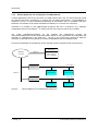
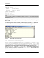
1
CAN-Ethernet-Gateway V2 System Manual Edition December 2014 SYS TEC electronic GmbH Am Windrad 2 · 08468 Heinsdorfergrund · Deutschland Telefon: +49 3765 38600-0 · Fax: +49 3765 38600-4100 Web: http://www.systec-electronic.com · Mail: [email protected] SYS TEC electronic GmbH – Systems House for Distributed Automation Status / Changes Status: released Date/ Version 16.05.2011 16.04.2012 26.04.2012 11.06.2013 Section 1.2.2 3 all 9 6.4.7 08.05.2014 03.06.2014 9 9 6.4.5 12.06.2014 9 17.09.2014 6.5, 6.6 24.11.2014 15.12.2014 6.4.1 6.4.7 9.2.1 L-1294e_10 Change Completion Updated list of CAN software Adjusted description Adjust text formatting Added section about ASCII protocol Added subsection about ASCII server configuration ASCII protocol extended ASCII format description for firmware 1.2.2 Added hint about BTP/TCP and EthCan.dll Link to ASCII parser demo added Note about INI-Format: Filter delimeter is INI file comment sign; Adjusted examples Added option UserBaud Added option Timestamp Added timestamp description Editor Stein Stein Stein Glau Stein Stein Stein Stein Stein Stein Stein Stein Stein Stein © SYS TEC electronic GmbH 2014 Product names used in this manual which are also registered trademarks have not been marked additionally. The missing © mark does not imply that the trade name is unregistered. Nor is it possible to determine the existence of any patents or protection of inventions on the basis of the names used. All the information in this manual has been checked carefully and is believed to be correct. However, it is expressly stated that SYS TEC electronic GmbH does not assume warranty or legal responsibility or any liability for consequential damages which result from the use or contents of this user manual. The information contained in this manual can be changed without prior notice. Therefore, SYS TEC electronic GmbH shall not accept any obligation. Furthermore, it is expressly stated that SYS TEC electronic GmbH does not assume warranty or legal responsibility or any liability for consequential damages which result from incorrect use of the hardware or software. The layout or design of the hardware can also be changed without prior notice. Therefore, SYS TEC electronic GmbH shall not accept any obligation. Copyright 2014 SYS TEC electronic GmbH. All rights reserved. No part of this manual may be reproduced, processed, copied or distributed in any way without prior written permission of SYS TEC electronic GmbH. Contact Address: Offer-Hotline: Technical Support: SYS TEC electronic GmbH Am Windrad 2 08468 Heinsdorfergrund GERMANY +49 3765 / 38600-2110 [email protected] +49 3765 / 38600-2140 [email protected] Fax: +49 3765 / 38600-4100 Website: http://www.systec-electronic.com L-1294e_10 © SYS TEC electronic GmbH 2014 Table of Contents TABLE OF CONTENTS 1 INTRODUCTION ...................................................................................................1 1.1 BASICS .....................................................................................................................................................1 1.2 APPLICATION AREAS ................................................................................................................................2 1.2.1 Connection of two CAN-networks via Ethernet .........................................................................2 1.2.2 Remote Diagnosis and Configuration of CAN-Networks .........................................................3 2 SCOPE OF DELIVERY .........................................................................................4 3 TECHNICAL DATA ...............................................................................................5 4 IMPLEMENTATION ..............................................................................................7 4.1 POWER SUPPLY .......................................................................................................................................7 4.2 NETWORK CONNECTION ..........................................................................................................................7 4.2.1 CAN-Bus Connection ....................................................................................................................7 4.2.2 Ethernet-Connection .....................................................................................................................7 4.2.3 USB-Device Interface....................................................................................................................8 4.3 STATUS DISPLAY .....................................................................................................................................8 4.4 BUTTONS ..................................................................................................................................................8 4.5 IMPLEMENTATION .....................................................................................................................................9 4.5.1 Standard Configuration .................................................................................................................9 4.5.2 Initial Configuration via USB-Device-Interface ..........................................................................9 4.5.3 Configuration and Operation through Telnet............................................................................12 5 DEVICE FUNCTION ............................................................................................13 5.1 OVERVIEW ..............................................................................................................................................13 5.2 INTERFACES ...........................................................................................................................................13 5.2.1 Basic Concept ..............................................................................................................................13 5.2.2 UDP/TCP-Server Interface .........................................................................................................14 5.2.3 UDP/TCP-Client Interface ..........................................................................................................14 5.2.4 CAN-Interface...............................................................................................................................14 5.2.5 Data logger-Interface ..................................................................................................................14 5.3 FILTERING ..............................................................................................................................................15 5.4 FILE SYSTEM ..........................................................................................................................................15 5.4.1 Layout ............................................................................................................................................15 5.5 DESCRIPTION OF IMPORTANT COMMANDS ............................................................................................16 5.5.1 cd ...................................................................................................................................................16 5.5.2 ls .....................................................................................................................................................16 5.5.3 rm ...................................................................................................................................................16 5.5.4 cat ..................................................................................................................................................16 5.5.5 version ...........................................................................................................................................17 5.5.6 exit .................................................................................................................................................17 5.5.7 reboot ............................................................................................................................................17 5.5.8 gatewayconfig ..............................................................................................................................17 6 GATEWAY CONFIGURATION ...........................................................................18 6.1 6.2 6.3 6.4 BASICS ...................................................................................................................................................18 SECTION [INTERFACES] .........................................................................................................................18 SECTION [CONNECTIONS] ......................................................................................................................18 SECTION [INSTANCEX] ...........................................................................................................................19 L-1294e_10 © SYS TEC electronic GmbH 2014 Table of Contents 6.4.1 Instance-Type CAN .....................................................................................................................19 6.4.2 Instance-Type DLOG ..................................................................................................................21 6.4.3 Instance-Type BTP_UDP_CAN_SRV ......................................................................................21 6.4.4 Instance-Type BTP_UDP_CAN_CLIENT ................................................................................21 6.4.5 Instance-Type BTP_TCP_CAN_SRV .......................................................................................21 6.4.6 Instance-Type BTP_TCP_CAN_CLIENT .................................................................................22 6.4.7 Instance-Type ASCII_TCP_SRV ...............................................................................................22 6.5 FILTERING ..............................................................................................................................................22 6.6 SAMPLE FOR A CUSTOMER-SPECIFIC CONFIGURATION-SCRIPT .........................................................23 6.7 CREATION OF A CONFIGURATION-SCRIPT ............................................................................................25 7 ERROR PROCESSING .......................................................................................26 7.1 7.2 7.3 8 ERROR SIGNALS OF THE CAN-ETHERNET-GATEWAY V2 ....................................................................26 ERROR MESSAGES VIA CAN .................................................................................................................27 STATUS OVERVIEW ................................................................................................................................27 SOFTWARE SUPPORT ......................................................................................28 8.1 CONNECTION OF CAN-ETHERNET-GATEWAYS V2 TO THE PC ...........................................................28 8.2 DRIVER INSTALLATION ON W INDOWS ...................................................................................................28 8.3 THE DYNAMIC LINKED LIBRARY ETHCAN.DLL ......................................................................................29 8.3.1 The Concept of EthCan.Dll .........................................................................................................29 8.3.2 The Function Interface of the EthCan.Dll .................................................................................30 8.3.2.1 8.3.2.2 8.3.2.3 8.3.2.4 8.3.2.5 8.3.2.6 8.3.2.7 8.3.2.8 8.3.3 8.3.4 8.3.5 8.3.5.1 9 EthCanGetVersion .................................................................................................................................. 30 EthCanInitHardware ............................................................................................................................... 30 EthCanDeinitHardware .......................................................................................................................... 34 EthCanReadCanMsg ............................................................................................................................. 36 EthCanWriteCanMsg ............................................................................................................................. 38 EthCanGetStatus .................................................................................................................................... 39 EthCanGetConnectionState .................................................................................................................. 41 EthCanResetCan .................................................................................................................................... 42 Description of Error Codes .........................................................................................................43 Description of CAN-Error Codes ...............................................................................................45 Application of DLL-Functions .....................................................................................................47 Demo-Project .......................................................................................................................................... 47 ASCII-PROTOCOL..............................................................................................49 9.1 ESTABLISHING CONNECTION .................................................................................................................49 9.2 TRANSMISSION FORMAT ........................................................................................................................49 9.2.1 CAN-Messages ............................................................................................................................49 10 FIRMWARE UPDATE .........................................................................................51 10.1 10.2 PREPARATION ........................................................................................................................................51 FIRMWARE DOWNLOAD .........................................................................................................................51 L-1294e_10 © SYS TEC electronic GmbH 2014 Index of Figures and Tables Index of Figures Figure 1: Transparent Connection of two CAN ............................................................ 2 Figure 2: Remote Diagnosis of CAN-Networks using a PC ......................................... 3 Figure 3: Device View .................................................................................................. 6 Figure 4: Configuration of the Tera Term (1) ............................................................. 10 Figure 5: Configuration of the Tera Term (2) ............................................................. 10 Figure 6: Start message of the CAN-Ethernet-Gateway V2 ...................................... 11 Figure 7: Checking the Current Configuration ........................................................... 12 Figure 8: Principle of the CAN-Ethernet-Gateway V2 ................................................ 13 Figure 9: Construction of the Hardware-Parameter Structure ................................... 31 Figure 10: Transfer Protocols of the CAN-Ethernet-Gateway V2 ................................ 31 Figure 11: Connection State of the CAN-Ethernet-Gateway V2 .................................. 32 Figure 12: Structure of a CAN-Message...................................................................... 37 Figure 13: Structure of the CAN-TimeStamp............................................................... 37 Figure 14: Structure of the CAN-Status-Structure ....................................................... 40 Figure 15: Desktop-Link for Demo-Program ............................................................... 48 L-1294e_10 © SYS TEC electronic GmbH 2014 Index of Figures and Tables Index of Tables Table 1: Configuration of the CAN-Plug Connection .................................................. 7 Table 2: Configuration of the Ethernet-Plug Connection ............................................ 7 Table 3: Meaning of Display Elements ....................................................................... 8 Table 4: Meaning of the Key ....................................................................................... 8 Table 5: Overview on Interfaces ............................................................................... 14 Table 6: Instance Types ........................................................................................... 18 Table 7: Options for Instance-Type CAN.................................................................. 20 Table 8: Options for Instance-Type DLOG ............................................................... 21 Table 9: Options for Instance-Type BTP_UDP_CAN_SRV...................................... 21 Table 10: Options for Instance-Type BTP_UDP_CAN_CLIENT ................................ 21 Table 11: Options for Instance-Type BTP_TCP_CAN_SRV ...................................... 21 Table 12: Options for Instance-Type BTP_TCP_CAN_CLIENT ................................ 22 Table 13: Options for Instance-Type ASCII_TCP_SRV ............................................. 22 Table 14: Construction of an Emergency-Message ................................................... 27 Table 15: Directory Structure of the CAN-Ethernet-Gateway V2l_Utility_Disk ........... 28 Table 16: Function range of software states .............................................................. 29 Table 17: Error Codes Interface Functions EthCan.Dll .............................................. 43 Table 18: CAN-Error Codes ....................................................................................... 45 L-1294e_10 © SYS TEC electronic GmbH 2014 Introduction 1 Introduction 1.1 Basics Until now the CAN-Ethernet-Gateway of the SYS TEC electronic GmbH has been the standard product for the connection of CAN-networks. Yet it had reached its capacity limit, the CAN-Ethernet Gateway V2 has been developed without these known limits. Internet communication via TCP/IP is distributing further within the industrial sector. With CANEthernet-Gateway V2, SYS TEC electronic Ltd. presents a solution which serves for interfacing CANnetworks through the Internet/Ethernet and to control the networks via remote access. The CANEthernet-Gateway V2 takes over communication and provides a transparent working application interface to the user based on CAN. A transparent, protocol-independent transmission of the CAN-Messages takes place, which serves for a large application area. Thus the CAN-Ethernet-Gateway can be applied with different CAN-protocols (e.g. CANopen, SDS, J1939, DeviceNet or company-specific protocols etc.) The CAN-Ethernet-Gateway V2 can be applied with a transfer rate up to 1MBit/s within CAN-networks according to CAN-specifications 2.0A (11-Bit CAN-identifier) ) and 2.0B (29-Bit CAN-Identifier). For each CAN-Message, a TimeStamp can be generated and transferred together with the date through the CAN-Ethernet-Gateway V2. The CAN-Ethernet-Gateway V2 can be set up via an asynchronous serial interface (UART to RS232 incl. hardware flow control) or a Telnet-connection. The user is able to adjust the functions of the CANEthernet-Gateway V2 to the particular application area. For the communication between the CAN-Ethernet-Gateways V2, an UDP/IP-based network protocol (BTP = Block Transfer Protocol) is used. Therewith CAN-Messages are transferred with a minimal time lag within the Ethernet. Time for establishing and cancelling of network connections of the TCP/IPprotocol is dropped. There is also the opportunity to transfer the CAN-Messages via TCP/IP Network-protocol. The design of the Gateway-Firmware is aligned with a high data throughput. The optimized buffer management works with a minimal effort for copying and buffering of data. Peak loads within the CANnetworks are covered. In case of a high data volume, several CAN-Messages are summarized to a UDP or TCP package and transferred in block. The CAN-Ethernet-Gateway V2 recognizes errors and sends Can-Messages (error messages) which contain the error reason. The CAN-identifier to be used for the error message) can be configured (see section 6.2). L-1294e_10 © SYS TEC electronic GmbH 2014 Introduction 1.2 Application Areas 1.2.1 Connection of two CAN-networks via Ethernet A typical application is the connection of two CAN-networks via Ethernet through great distances. There is a CAN-Ethernet-Gateway V2 processing in each CAN-network. CAN-Messages are transferred transparently between the CAN-Ethernet-Gateways V2. The CAN-Ethernet-Gateways V2 firmware allows for a filtering of CAN-Messages to be transferred, so that only relevant data are transferred via Ethernet. The principal opportunities of network configuration with CAN-Ethernet-Gateways V2 are demonstrated in Figure 1 and Figure 2 below: CAN-Device A CAN-Device B CAN - Bus 1 CAN-Ethernet Gateway V2 Ethernet Intranet Ethernet CAN-Ethernet Gateway V2 CAN - Bus 2 CAN-Device C Figure 1: L-1294e_10 CAN-Device D Transparent Connection of two CAN © SYS TEC electronic GmbH 2014 Introduction 1.2.2 Remote Diagnosis and Configuration of CAN-Networks A further application exists in the connection of a CAN-network with a PC. The user exclusively needs the network connection via Ethernet, to connect with the distant Can-network. A CAN-hardware is needed on the PC. A virtual CAN-Ethernet-Gateway as PC-software (DLL) is available under MSWindows. The interface of the virtual CAN-Ethernet-Gateway V2 conforms to a CAN-driver. Therewith it is possible to use CAN-standard programs that use a CAN-driver (e.g. CANopen configuration tools as ProCANopenTM or CAN-Tools from Port, further products upon request). The virtual CAN-Ethernet-Gateway for PC extends the CAN-network through the Internet/Intranet/Ethernet until the office and therefore allows for new opportunities of configuration and diagnosis of CAN-networks in the field level. The PC in the control level requires an Ethernetconnection to the field level by offering the comfort of established CAN and CANopen tools. Function and parameter of the Gateway can be changed remote-controlled via the Telnet-Protocol. Service PC Intranet or Internet Ethernet virtual Gateway CAN to Ethernet CAN - Bus 1 CAN-Ethernet Gateway V2 CAN-Device A Ethernet CAN - Bus 2 CAN-Ethernet Gateway V2 CAN-Device C Figure 2: L-1294e_10 CAN-Device B CAN-Device D Remote Diagnosis of CAN-Networks using a PC © SYS TEC electronic GmbH 2014 Scope of Delivery 2 Scope of Delivery The delivery of the CAN-Ethernet-Gateways V2 includes: - 3004010 CAN-Ethernet-Gateway V2 1xCAN (Standard Version) inside enclosure for carrier rail construction, incl. a 2-pin peelable bolted connection and a 2x5 pol. control spring connection 3004011 CAN-Ethernet-Gateway V2 2xCAN (Standard Version) inside enclosure for carrier rail construction, incl. a 2-pin peelable bolted connection and a 2x5 pol. control spring connection 3004013 CAN-Ethernet-Gateway V2 1xCAN (Extended Version) inside enclosure for carrier rail construction, incl. a 2-pin peelable bolted connection and a 2x5 pol. control spring connection - 3004014 CAN-Ethernet-Gateway V2 2xCAN (Extended Version) inside enclosure for carrier rail construction, incl. a 2-pin peelable bolted connection and a 2x5 pol. control spring connection - WK806 L-1314 USB-connection cable plug series - plug series B 1,8m Product insert sheet or - or - or L-1294e_10 © SYS TEC electronic GmbH 2014 Technical Data 3 Technical Data The CAN-Ethernet-Gateway V2 functionalities : 1 exhibits the following technical data and System software: Linux Control and monitor of remote CAN-networks via the internet Connection of two CAN-networks Gateway configurable via Telnet,, FTP (remote maintenance) or serial interface via USBConnector File system for configuration data Flexible configuration through implementation of several interfaces (see section 4.2) Large filter mechanisms for CAN-Messages Generation of a timestamp for CAN-Messages Connection to Windows-Application programs for CAN and CANopen Illuminating diodes (LED) for illumination of the Gateway, 8 St. in Standard Version, 12St. in Extended Version Generation of CAN-error messages High data throughput 10Base-T/100Base-TX interface (10/100Mbit/s) with RJ45-Connector 2 CAN-interfaces acc. to CiA1 102 up to 1MBit/s, Highspeed CAN acc. to ISO11898-1/2, DCcoupled 2 CAN-Bus- plug-clamping connections: 2x5-pin each acc. to CiA 102 or DeviceNet-Standard Support of 11-Bit CAN-Identifier and 29-Bit CAN-Identifier RS232-interface (type-depending) via USB-Device-connector with USB-serial converter or directly at the USB-Device interface of the CPU Power supply: 24VDC +20% -60%, reverse-polarity protected Current consumption: ca. 100mA Power-plug connector: 2-pin. drawable bolted connection Size without plug connector: 70 x 100 x 61 (L x B x H) mm³ for DIN/EN-Carrier rail construction Enclosure protection degree: IP20 Operating temperature range: 0°C bis +70°C CiA, CAN in Automation, international users and manufacturers group L-1294e_10 © SYS TEC electronic GmbH 2014 Technical Data Figure 3: Device View Types of development Basic Variant: - Power Supply CPU-Core with 32MiB SDRAM (32bit) and 4MiB Flash(16bit) Ethernet-Interface 1x or 2x CAN-Interface, DC-coupled USB-Connector connected with microcontroller-internal USB-Device-Interface 6 LEDs placed next to USB-interface Full Variant: - Parts of the Basic Variant (except LEDs) 10 LEDs placed at module front cover Real time clock with battery back-up 2kiB EEPROM for data from user-applications USB via USB-Serial Converter at DRxD/DTxD of the microcontroller L-1294e_10 © SYS TEC electronic GmbH 2014 Implementation 4 Implementation 4.1 Power Supply For the operation of the device, a direct voltage of 24V (60% to +20%) is needed. The current consumption of the device is about 100mA. Connection occurs through a 2-pin, peelable bolted connection. The connection is marked on device ("+" = "L+" / "-" = "0G"). The correct connection of the supply voltage is signalized via the voltmeter “power” . 4.2 Network Connection 4.2.1 CAN-Bus Connection For the CAN-network, two 2x5-pin peelable push terminal connectors are available. (Fitting plug: Weidmüller Minimate B2L 3.5/10). The configuration of the array equals the DeviceNet or CANopenStandard respectively. All Pins of both arrays on the plugs are connected with each other. Therefore it is possible to connect the Bus through at the module. The power supply for the CAN-Bus (Pin 5A/5B at 2x5-pol. plug connector) is disconnected within the gateway. The supply voltage of both DC-decoupled channels is energized internally via 2 DC/DCconverters. The shielded connector only serves for protection of the respective CAN-channel. There is no connection between the shield-connectors of CAN0, CAN1, USB and Ethernet. The shield therefore is to connect additionally with PE near the module. 2x5-pin. 1 2 3 4 5 Table 1: 4.2.2 Name V-(CAN_GND) CL (CAN_L) SH (CAN_SHLD) CH (CAN_H) V+ (CAN_V+) Description CAN Ground CAN_L bus line CAN Shield CAN_H bus line disconnected Configuration of the CAN-Plug Connection Ethernet-Connection The Ethernet (10Base-T/100Base-TX) is connected by means of a usual CAT 3 or CAT 5network cable with a RJ45-plug. For the direct connection (without hub or switch) of a CAN-Ethernet-Gateway V2 with a PC, a Crosslink Cable is needed. The Ethernet-connection is DC-decoupled from the CANEthernet Gateway V2. Pin 1 2 3 4 5 6 7 8 Table 2: L-1294e_10 Name TX+ TXRX+ n.c. n.c. RXn.c. n.c. Description Transmit Data + Transmit Data Receive Data + Disconnected Disconnected Receive Data + Disconnected Disconnected Configuration of the Ethernet-Plug Connection © SYS TEC electronic GmbH 2014 Implementation 4.2.3 USB-Device Interface The CAN-Ethernet-Gateway V2 features a USB Device-Interface which is connected to it via a USBplug of Type B. This interface allows for configuration of the CAN-Ethernet Gateways V2. This connection is especially made for initial configuration (see section 3.5). The USB-Device-Interface is not DC-decoupled. 4.3 Status Display To display the operating status, 10 or 8 LEDs are needed (see Table 3). The displays are summarized on the LED-board according to the CAN-nets and represent their status. Furthermore, there is a diagnosis-LED of the gateway application available. Only available at completion stage At the completion stage, both Ethernet-LEDs are available at the connector and board as well LED-Description Power/24V CAN state 0/1 CAN error 0/1 Diagnose Link Speed CAN traffic 0/1 Table 3: Definition Power Supply OK CAN-Bus 0/1 in use Error during data transfer to CAN-Bus 0/ 1 (see section 7.1) Diagnosis-LED of the gateway application Green: Ethernet-link available, Cabling OK Flashing: Ethernet-traffic Off: no Ethernet-link Orange: 100MBit/s Off: 10MBit/s Signaling of data traffic on the CAN-Bus 0/1 Meaning of Display Elements 4.4 Buttons The CAN-Ethernet-Gateway V2 has two key buttons (see Table 4), defined as follows: Key Button-No.: Description Definition 1 Reset Short press will reset the module and causes a restart 2 Boot Pressing the key during booting may cause a reset of configuration options, to ensure access to the module in emergency situations Reset includes the following: Passwords of root and gw are deleted Network configuration Gatewayconfig Table 4: L-1294e_10 Meaning of the Key © SYS TEC electronic GmbH 2014 Implementation 4.5 Implementation 4.5.1 Standard Configuration Factory-provided, the CAN-Ethernet-Gateway V2 contains the following standard configurations (preparation of a configuration-script see section 6.1): Ethernet/Internet-configurations IP-address of the CAN-Ethernet-Gateway V2: Subnet-Mask: Standard-Gateway: DNS-Server: CAN-Bus 0 UDP1-Server TCP-Server Data logger 192.168.10.49 255.255.255.0 192.168.10.1 192.168.10.5 CAN-settings CAN-Bitrate: CAN-Identifier for error messages 1Mbit/s 0xFC, but disabled Serial interface via USB-Device-connection baud rate: Data bit: Parity: Stoppbit: Protocol: 115200 Baud 8 none 1 none 4.5.2 Initial Configuration via USB-Device-Interface Prior to the transfer of CAN-Messages, the CAN-Ethernet-Gateway V2 is to configure as needed. For this purpose, the following steps are necessary: 1 Install the appropriate driver for the USB-Interface: CP210x for completion or CDC-ACM for the other case. For Linux, please use the kernel driver cp210x or cdc-acm respectively. For Windows, both drivers are installed on the CD enclosed. Both drivers provide a serial interface that can be accessed with a common terminal emulator. Connect the delivered USB-cable with the USB-Device-Interface of the CAN-Ethernet-Gateway V2 and a free USB-Interface on the PC. Please start a terminal program on your PC (the program „Terra Term“ is used in the following; in case of using another terminal program, the correct settings are to take) Set up the interface baud rate configuration (see Figure 4 and Figure 5) BTP: Block Transfer Protocol for transferring CAN-Telegrams via UDP/IP L-1294e_10 © SYS TEC electronic GmbH 2014 Implementation Figure 4: Configuration of the Tera Term (1) Figure 5: Configuration of the Tera Term (2) Please ensure that the power supply is connected correctly and switch on the supply voltage Please consider that only at the Full variant, the emulated serial interface is created with the connection of the power supply and can be used immediately. The boot messages are visible at this variant only. In the variant with CDC-ACM, the interface is not created before Linux has booted. L-1294e_10 © SYS TEC electronic GmbH 2014 Implementation Figure 6: Start message of the CAN-Ethernet-Gateway V2 In both cases, Login prompt appears directly after the boot process; Login and password are requested to access the system. The Login is gw with the standard password gw. For administrative tasks, e.g. a firmware update, the user root with the standard password root is intended. This user provides access to the whole system. Note: Take care while working as user root, as in case of non-booting, a system recovery without further support in principle is only possible at Full variant. As the CAN-Ethernet-Gateway V2 is based on Linux with a JFFS2-file system, there are different commands to work with it. The most important commands are explained in the following. Busybox is installed with a typical selection of programs that, among others, serve as navigation. These are: ls pwd cd rm sync to display the content of the current directory, to display the current directory, to change the current directory, to delete a directory/data, to ensure that all data of the JFFS2-file system have been stored in the non-volatile storage (NOR-Flash). Note: The program sync is usually not necessary, as the files are automatically fed into the flash memory after a certain time/data volume. However, Synchronizing can be enforced by means of this command. A complete list of the Busybox-Programs is available on running busybox without any arguments. For gateway configuration, the program gatewayconfig is available at /usr/sbin/. Requested without parameters, supported options as well as the current configuration is listed, e.g. L-1294e_10 © SYS TEC electronic GmbH 2014 Implementation gatewayconfig Usage: gatewayconfig <option> <value> available options: ipaddr host IP address netmask network mask dnsip DNS server IP address gatewayip gateway IP address Current configuration: ipaddr=192.168.10.49 netmask=255.255.255.0 dnsip=192.168.10.5 gatewayip=192.168.10.1 Note: gatewayip is the IP-address of the Default-IP gateway, not the one of the CAN-Ethernet gateway itself, which is ipaddr! At this point, the settings concerning IP-address, Network Mask, Gateway and DNS-Server should be set up before running the program. The IP-address 0.0.0.0 signifies automatic network configuration through DHCP. The settings will become effective after restart. For this purpose, the command reboot can be used. After the restart, please check the current configuration via the program gatewayconfig. Therewith, the network configuration is finished and the gateway can be run via Ethernet (e.g. Telnet). Figure 7: 4.5.3 Checking the Current Configuration Configuration and Operation through Telnet At current operation of the CAN-Ethernet-Gateway V2, the configuration can be carried out via Telnet (TCP-Port 23). The scope of operation is the same as with USB-Device-Interface. Access via Telnet permits the configuration of remote CAN-Ethernet-Gateways V2. For it, a one-time configuration of the IP-address (see section 4.5.3) is needed. Without this one-time configuration of the IP-address, the CAN Ethernet-Gateway V2 is accessible through its Standard-configuration (see section 4.5.1). When working on Linux, the program telnet can be used. A default windows installation already includes a Telnet-Client. This can be accessed through telnet <Address>.Alternatively the PuTTY application for the serial interface can be used. After the Login, the procedure is the same as via USB-Device. L-1294e_10 © SYS TEC electronic GmbH 2014 Device Function 5 Device Function 5.1 Overview The CAN-Ethernet-Gateway V2 contains several interfaces for operation and control. It is structured as follows: CAN Interface can0 Input filter Linux Data logger Output filter Gateway FTP CAN Interface can1 Telnet CAN Input filter Output filter File upload/ download Shell access BTP 1 ... BTP n Ethernet Figure 8: Principle of the CAN-Ethernet-Gateway V2 5.2 Interfaces 5.2.1 Basic Concept The exchange of CAN-Messages occurs through interfaces. An interface delivers the connection between the gateway and a corresponding remote station, which has a different function. Several interfaces can be enabled. The most important interfaces in this context are CAN for the CAN-Interface and BTP_UDP_CAN_SRV resp. BTP_TCP_CAN_SRV for an Ethernet-Interface according to the Block-Transfer-Protocol. While the CAN-Interface is sending and receiving messages through the hardware to a CAN-Net, the UDPInterface is responsible for the tunneling of messages via UDP/IP/Ethernet. L-1294e_10 © SYS TEC electronic GmbH 2014 Device Function Available interfaces CAN UDP-Client UDP-Server TCP-Client TCP-Server Data logger Table 5: Type CAN-Bus BTP_UDP_CAN_CLIENT BTP_UDP_CAN_SRV BTP_TCP_CAN_CLIENT BTP_TCP_CAN_SRV DLOG Overview on Interfaces The UDP-interface is transferring the CAN-Messages based on the UDP-Protocol while the TCPInterface is using TCP as transport protocol instead. Both types of interfaces are identical in their function but differ regarding their rate of transmission. The data logger-interface stores CAN-Messages into a log file to be configured. Thereby, unwanted CAN-Messages can be filtered out. All interfaces are instanceable and therefore can be used several times, if needed. 5.2.2 UDP/TCP-Server Interface The UDP-Server-Interface (BTP_UDP_CAN_SRV) waits for UDP-connection requests from another gateway and finally generates a new UDP-connection that is used for an exchange of CANMessages. According to that, the TCP-Server (BTP_TCP_CAN_SRV) waits for TCP-connection requests. To be able to react on TCP- as well as UDP-based requests, a TCP - as well as a UDP-ServerInterface - have to exist at the gateway. The creation of interfaces occurs in the configuration file (see section 6 “Gateway”). 5.2.3 UDP/TCP-Client Interface The UDP-Client Interface provides a tunnel via UDP/IP/Ethernet to enable sending and receiving of messages. At the TCP-Client Interface, the tunnel is operated via TCP/IP/Ethernet. The creation of interfaces occurs in the configuration file (see section 6 “Gateway”). 5.2.4 CAN-Interface A CAN-Interface delivers CAN-Messages to the gateway where they can be processed via Ethernet, data logger or a further CAN-Bus. The creation of interfaces occurs in the configuration file (see section 6 “Gateway”). 5.2.5 Data logger-Interface The data logger-Interface allows for storing messages into configurable data file. Depending on to location within the file system, the log file is stored temporary until the next reboot or persistent in the flash memory. L-1294e_10 © SYS TEC electronic GmbH 2014 Device Function The creation of interfaces occurs in the configuration file (see section 6 “Gateway”). 5.3 Filtering Filtering is based on the CAN-Identifiers. The CAN-Ethernet-Gateway V2 processes all sent and received data using of filter lists within the instances. Therewith, data transfer can be reduced, e.g. only messages of a special group of CAN-Identifiers (CAN-IDs) are forwarded. According to the type of instance, separated filters can be configured for receiving or sending. Furthermore, 11Bit and 29 Bit CAN-IDs are configured separately. Key names for the single instance types are described in section 6.4. The general syntax is demonstrated in section 6.5. 5.4 File System 5.4.1 Layout There is a file system integrated in the CAN-Ethernet-Gateway V2 that allows for configuration changes of the gateway regarding the operating time. Furthermore, the opportunity does exist to store files non-volatile in a NOR-flash. Structure of the file system (excerpt): . |-- bin |-- dev |-- etc | `-- ceg |-- home |-- proc |-- sbin |-- sys |-- tmp |-- usr | |-- bin | `-- sbin `-- var `-- log The tree below /home represents the users area where, among others, the gateway configuration is stored. The directories /bin and /usr/bin contain programs, the user can use at any time. Programs stored in /sbin and /usr/sbin have been installed for administration purposes. The directory /tmp is a file system that is stored in the main memory and therefore can be used for temporary data. Those data will get lost after a restart. There are several commands available for navigation within the file system (see section 5.5). L-1294e_10 © SYS TEC electronic GmbH 2014 Device Function 5.5 Description of Important Commands There is busybox available at the CAN-Ethernet-Gateway V2 with a typical selection of Unix/Linuxcommands. In most cases, the programs offer a bit less functionality than its counterpart on a Desktop-Linux. However, the most important functions are available on here as well. Some commands are described in the following, to ensure a quick introduction to the topic. 5.5.1 cd Format: cd [<dir>] Definition: Command cd serves for change to the stated directory <dir>. Thereby, .. is the parent directory. If cd is specified without an argument, a change to the user directory (/home) occurs. 5.5.2 ls Format: ls [<dir>] Definition: Command ls shows the file of the current or indicated directory. With option -l further information are displayed for each single file and directory Sample: ls -l /etc/ceg/ -rw-r--r-- 1 root root 5.5.3 578 Jun 10 2010 default.rc rm Format: rm <fname> Definition: Command rm allows for deletion of files and directories. <fname> corresponds to the name of the file to delete. Option -r (recursive) has to be specified additionally. Alternatively, rmdir can be used for deleting directories. Sample: rm /home/datei 5.5.4 deletes file file in directory /home cat Format: cat <fname> Definition: Command cat displays the content of the file <fname>. Sample: cat file displays the content L-1294e_10 © SYS TEC electronic GmbH 2014 Device Function 5.5.5 version version Format: Definition: Command version shows the version of the CAN-Ethernet-Gateway V2-Firmware. Sample: version V1.01 2010.07.0 CAN Ethernet Gateway V2 0.5.0-00042-g25ba83c U-Boot version: 2010.03-00042-gacdb25b PCB Version: 4248.1 5.5.6 exit Format: exit Definition: Command exit terminates the Telnet-session. Strg+D can be used alternatively. 5.5.7 reboot Format: /sbin/reboot Definition: Command reboot restarts the CAN-Ethernet-Gateway V2 (a software reset is asserted). The absolute path is needed, as directory /sbin does not exist in PATH for the restricted user. 5.5.8 gatewayconfig Format: /usr/sbin/gatewayconfig Definition Command gatewayconfig serves for network configuration through the bootloader. Without an argument, options available as well as the current configuration are displayed. As root rights are needed for it, this program has been installed with the SUID-Bit and can be used by everyone. L-1294e_10 © SYS TEC electronic GmbH 2014 Gateway Configuration 6 Gateway Configuration 6.1 Basics The configuration of the CAN-Ethernet-Gateway V2 can occur through different ways; via the USBInterface, with a terminal program (see section 4.5.2), a Telnet-connection via Ethernet (see section 4.5.3) or through download of the configuration file via FTP. The configuration of the CAN-Ethernet-Gateway V2 occurs through a configuration file. With just a few exceptions, the options are optional and are preset with appropriate standard values, if they have not been defined yet. The format corresponds to the Windows-INI-format. The configuration file is divided in several sections that configure different parts respectively. 6.2 Section [Interfaces] Within this section, the single interfaces or instances are defined. The key is a serial number starting at 0. The value to it is the name of the instance and the type, separated through spaces. The type is special as the name as well defines the CAN-instance of the driver. Therefore, CAN0 means CAN-Bus 0 and CAN1 uses CAN-Bus 1. Identifier type CAN DLOG BTP_UDP_CAN_SRV BTP_UDP_CAN_CLIENT BTP_TCP_CAN_SRV BTP_TCP_CAN_CLIENT Table 6: Interface type Can-Interface Data logger BTP-UDP-Server BTP-UDP-Client BTP-TCP-Server BTP-TCP-Client Instance Types Sample: [Interfaces] 0=CAN0 CAN 1=Btp BTP_UDP_CAN_SRV 2=Remote1 BTP_TCP_CAN_CLIENT 3=Dlog DLOG With this configuration, a CAN-Interface, BTP-UDP-Server, UDP-TCP-Client and a data logger are set up. Configuration to the single interfaces is described separately. 6.3 Section [Connections] In this section, the single instances are connected with each other. For each instance a list can be defined, from which other instances messages shall be received. Sample (continued): [Connections] L-1294e_10 © SYS TEC electronic GmbH 2014 Gateway Configuration CAN0=Btp DLog=CAN0 Btp Btp=CAN0 Remote1=CAN0 In this example, all messages received through the BTP-UDP-Server are sent via CAN and reversed. Additionally, messages from the CAN-Bus and BTP-UDP-Server are stored by data logger. Furthermore, the messages of the CAN-Bus are sent via BTP-TCP. 6.4 Section [InstanceX] In the sections [InstanceX] where X corresponds to the number from [Interfaces], the single instances are configured. The concrete options differ and depend on the instance type. 6.4.1 Instance-Type CAN Baudrate UserBaud CAN-baud rate in kBaud. Can be overwritten by UserBaud. Values allowed: 20, 50, 100, 125, 250, 500, 800, 1000 Standard: 125 User specified bitrate. If set, any setting in Baudrate is ignored. Standard: undefined ErrorMsgId Upon any questions about calculation or possibility of custom bitrates please contact the support at [email protected] and visit our homepage at http://www.systec-electronic.com Acceptance Code Register Standard: 0 Acceptance Mask Register Standard: 0xFFFFFFFF Size of the receive buffer in the CAN-driver: Standard: 5000 Size of the send buffer in the CAN-driver: Standard: 5000 Filter list with standard-CAN-IDs not allowed to be received Standard: <empty> Filter list containing Standard-CAN-IDs allowed to be received Standard: <empty> Filter list containing Standard-CAN-IDs that shall not be sent Standard: <empty> Filter list containing Standard-CAN-IDs that shall be sent Standard: <empty> Filter list containing extended CAN-IDs not allowed to be received Standard: <empty> Filter list containing extended CAN-IDs allowed to be received Standard: <empty> Filter list containing extended CAN-IDs that shall not be sent Standard: <empty> Filter list containing extended CAN-IDs that shall be sent Standard: <leer> Enables the Listen-only-Mode of the CAN-Controllers 0: disabled 1: enabled Standard: 0 Enables sending of CAN-Error Messages 0: disabled 1: enabled Standard: 0 CAN-ID of the CAN-Error Message L-1294e_10 © SYS TEC electronic GmbH 2014 Acr Amr LowbufRxMaxEntries LowbufTxMaxEntries FilterStdRejectIn FilterStdAllowIn FilterStdRejectOut FilterStdAllowOut FilterExtRejectIn FilterExtAllowIn FilterExtRejectOut FilterExtAllowOut ListenOnly EnableErrorMsg Gateway Configuration Only Standard-CAN-IDs supported Standard: 0xFE Table 7: L-1294e_10 Options for Instance-Type CAN © SYS TEC electronic GmbH 2014 Gateway 6.4.2 Configuration Instance-Type DLOG LogFile FilterStdReject FilterStdAllow FilterExtReject FilterExtAllow Table 8: 6.4.3 Options for Instance-Type DLOG Instance-Type BTP_UDP_CAN_SRV LocalPort Port the BTP-UDP-Server is connected to Standard: 8234 Indicates after how many ms the BTP-Transfer shall start at the latest Standard: 0 Indicates after how many CAN-Messages the BTP-Transfer shall start at the latest Standard: 1 TriggerTime TriggerCount Table 9: 6.4.4 Options for Instance-Type BTP_UDP_CAN_SRV Instance-Type BTP_UDP_CAN_CLIENT RemoteIP RemotePort ReconnectionType TriggerTime TriggerCount Table 10: 6.4.5 File name of the Log-file has to be specified here! Filter list containing Standard-CAN-IDs that shall not be saved Standard: <empty> Filter list containing Standard-CAN-IDs to be saved Standard: <empty> Filter list containing extended CAN-IDs to be saved Standard: <empty> Filter list containing extended CAN-IDs to be saved Standard: <empty> IP the BTP-UDP-Client shall connect to Standard: 0.0.0.0 Port the BTP-UDP-Client shall connect to Standard: 8234 Settings for automatic reconnection in case of connection loss 0: no reconnection 1: reconnection, if message is to be sent 2: immediate reconnection (Standard: 2) Indicates after how many ms the BTP-Transfer shall start at the latest Standard: 0 Indicates after how many CAN-Messages the BTP-Transfer shall start at the latest Standard: 1 Options for Instance-Type BTP_UDP_CAN_CLIENT Instance-Type BTP_TCP_CAN_SRV LocalPort TriggerTime TriggerCount Table 11: L-1294e_10 Port the BTP-UDP-Server is connected to Standard: 8234 Indicates after how many ms the BTP-Transfer shall start at the latest (Standard: 0) Indicates after how many CAN-Messages the BTP-Transfer shall start at the latest (Standard: 1) Options for Instance-Type BTP_TCP_CAN_SRV © SYS TEC electronic GmbH 2014 Gateway Configuration Note: For a TCP BTP connection between CAN-Ethernet-Gateway V2 and a Windows PC using EthCan.dll there can be a significant latency due to a full TCP window. To prevent this it is recommended to set TriggerTime and TriggerCount to 10 at least. 6.4.6 Instance-Type BTP_TCP_CAN_CLIENT RemoteIP RemotePort ReconnectionType TriggerTime TriggerCount Table 12: IP the BTP-UDP-Client shall connect to Standard: 0.0.0.0 Port the BTP-UDP-Client shall connect to Standard: 8234 Settings for automatic reconnection in case of connection loss 0: no reconnection 1: reconnection, if message is to send 2: immediate reconnection Standard: 2 Indicates after how many ms the BTP-Transfer shall start at the latest (Standard: 0) Indicates after how many CAN-Messages the BTP-Transfer shall start at the latest (Standard: 1) Options for Instance-Type BTP_TCP_CAN_CLIENT Note: For a TCP-BTP-connection between CAN-Ethernet-Gateway V2 and the CAN-Ethernet-Gateway V1, the result can be an overload of Gateway V1 with TCP due to performance differences. To prevent message loss and failures, it is recommended to set TriggerTime and TriggerCount to 10 at least. According to the concrete CAN-Bus-Message volume, those values may be increased further. 6.4.7 Instance-Type ASCII_TCP_SRV LocalPort Port the ASCII-TCP-Server is connected to Standard: 12000 Set to non-zero to enable sending timestamps on ASCII protocol Standard: 0 Timestamp Table 13: Options for Instance-Type ASCII_TCP_SRV 6.5 Filtering Filtering options are the same for all instances, if supported. There are separate settings for standardand extended CAN-IDs (11 or 29 Bits). Settings can be made separately for sending and receiving; e.g. which messages shall be received and which rejected. Sending and receiving may be configured different for the particular instance. Therefore receiving for the CAN-Instance means the forwarding of CAN-Messages from the CAN-Bus to the gateway. Sending means the forwarding of CAN-Messages from the Gateway to the CAN-Bus. It is therefore possible that a receiving of a message via the CAN-interface is allowed. However, the data logger may not save the message after it has been forwarded to it. For some instances, e.g. the data logger, there are only filter settings available for “receiving”, as the data logger cannot create any messages by itself. In general, there are only messages forwarded, whose ID has been accepted (Accept-Rule); but has not been rejected explicitly (reject-rule). This means that without settings, all messages are rejected. For all filters, the following syntax applies, which can be specified as value within the configuration file: <FilterList> L-1294e_10 := [<FilterEntry>[;<FilterList>]] © SYS TEC electronic GmbH 2014 Gateway Configuration <FilterEntry> <CanIdLow> <CanIdHigh> := <CanIdLow>-<CanIdHigh> lowest CAN-ID for filter area highest CAN-ID for filter area e.g. FilterStdAllowIn=0x0-0x7ff Allows for receiving of all 11Bit CAN-IDs FilterStdAllowIn=0x0-0x7ff FilterStdRejectIn="0x251-0x251;0x300-0x301" Allows for receiving of all 11Bit CAN-IDs except, 0x251 and between 0x300 and 0x301.To filter single CAN-IDs, the same value has to be set for the lowest and highest CAN-ID, e.g. "0x50-0x50;" to add CAN-ID 0x50 to the filter list. Note: Because ';' is the comment sign in the INI file format, any filter configurations must be enclosed within "" if more than one filter is used. 6.6 Sample for a Customer-Specific Configuration-Script In the following a sample configuration with explanations is shown: [Interfaces] 0=CAN0 CAN 1=Btp BTP_UDP_CAN_SRV 2=Dlog DLOG The single interfaces are entered in this area, in this case a CAN-interface for Bus 0 (refer to section 6.2). Additionally, there is a BTP-UDP-Server and a data logger. [Connections] CAN0=Btp DLog=CAN0 Btp Btp=CAN0 In this area, the single instances are connected with each other. In the following example, CAN is connected with BTP in both directions and the data logger receives all CAN-Messages from the CANBus and BTP. [Instance0] BaudRate=1000 FilterStdRejectIn="0x251-0x251; 0x300-0x301" FilterStdAllowIn=0x0-0x7ff FilterStdAllowOut=0x0-0x7ff Instance 0 refers to key 0 from [Interfaces] and therefore, a CAN-interface exists. The baud rate is set to 1000kBaud. The filters allow for a sending and receiving of all 11Bit CAN-IDs, whereas the IDs 0x251, 0x300 and 0x301 are not accepted for receiving. [Instance1] LocalPort=8234 The BTP-Server uses the UDP-Port 8234 and waits for connections. [Instance2] FilterStdAllow="0x25A-0x25A; 0x250-0x252" LogFile=/tmp/logfile.txt L-1294e_10 © SYS TEC electronic GmbH 2014 Gateway Configuration The data logger saves all data in file /tmp/logfile.txt and only saves CAN-Messages with the following IDs: 0x250, 0x251, 0x252 and 0x25a. L-1294e_10 © SYS TEC electronic GmbH 2014 Gateway Configuration 6.7 Creation of a Configuration-Script There is the opportunity to create or edit the configuration file directly within the Linux console. For this purpose, access via the serial console or Telnet is necessary. The text editors vi (a reduced variant within the busybox) and nano are installed on the module and can be used as preferred. For further information it is referred to the particular websites (http://www.vim.org/docs.php, http://www.nano-editor.org/docs.php). As an alternative, the configuration can be created or edited on your PC as well and can be copied to the gateway via FTP. For an introduction, the standard file that is available can be copied from /etc/dec/default.rc to /home/ceg/default.rc and edited there. Note: The configuration file must have the Unix-end of line (linefeed only) in either case. L-1294e_10 © SYS TEC electronic GmbH 2014 Error Processing 7 Error Processing 7.1 Error Signals of the CAN-Ethernet-Gateway V2 Errors are signalized through LED-light up or through a n entry written in the systemlog. This can be found at /var/log/messages. The following errors are indicated: Link connection impossible via BTP-Interface Possible causes: No connection to the configured server possible or connection has been declined Gateway: Entry in the systemlog CAN-RxBuffer-overflow, loss of CAN-Message Possible causes: CAN-Busload too high Receive buffer selected too small (for settings see section 5.2.4) Gateway: CAN-Error-LED lights up shortly CAN-TxBuffer-overflow CAN-Messages are enqueued too fast in the CAN-send buffer (e.g. through high busload and low priority of CAN-IDs to be sent) Appropriate CAN-Message is rejected Gateway: CAN-Error-LED lights up shortly BTP-TxBuffer-overflow no CANtoBTP-buffer available -> loss of CAN-Messages Gateway: Entry in the systemlog BTP-RxBuffer-overflow no BTPtoCAN-Buffer available -> loss of CAN-Messages Gateway: Entry in the systemlog Error during sending or receiving via BTP e.g. if the receiver has no free buffer or in case of a timeout general: CAN to TCP/IP-send buffer is rejected -> loss of CAN-Messages Gateway: Entry in the systemlog CAN-Busoff Error possible causes: CAN-Bus-cabling, wrong CAN-Bitrate, Hardware-error Gateway: CAN-Error LED lights up as long as the CAN-telegram has been sent or received successfully. L-1294e_10 © SYS TEC electronic GmbH 2014 Error Processing 7.2 Error Messages via CAN To evaluate the state of the CAN-net gateway, sending of error messages (Emergency-messages) according to the CANopen standard is possible Via the option EnableErrorMsg ErrorMsgId during the configuration of the CAN-interface sending of error messages can be enabled with the appropriate identifier in the CAN-Ethernet-Gateway V2. In the standard configuration sending is disabled. The format of the error message is specified as follows: Byte 0 1 Content EmergencyCode Table 14: 2 ErrorRegister 3 Interface number 4 5 Error-Code 6 reserved 7 reserved Construction of an Emergency-Message The Emergency-Code can consist of the following values: 0x1000: 0x8140: 0x0000: if a new, general error has occurred Node comes from the CAN-Busoff Device has no errors The error register is 0x80, in case that no further errors exist. The error register is 0x80, if errors do exist and 0x00, if all errors have been fixed. In the following, the number of interface, where the error has occurred and a bitmask that indicates which errors exist are indicated. In case of a 2-byte-long code (Byte 0,1 and 4,5), the higher part is sent last, e.g. 00 10 for 0x1000. The following bits of the error code are defined: 0x0000 Error-free 0x0001 Buffer overflow while receiving 0x0002 Buffer overflow while sending 0x0004 Buffer overflow in the CAN-Controller 0x0008 CAN-ACK-error (Acknowledge error) 0x0010 CAN-Warning-Limit is reached 0x0020 CAN-Passive mode is reached 0x0040 Devices in CAN-Busoff 0x0080 Error while message is sent 0x0100 Error while message is received 0x0400 Common error of the CAN-Controller, internal Hardware error of the SJA-1000 (StuffError, Form-Error, CRC-Error) 7.3 Status Overview Script support-info at /usr/sbin/ is for support inquiries. It provides an overview on the configuration and error messages that is saved in file /tmp/support-info.txt. This file is included in deliveries concerning support inquiries. Additionally, information is displayed on the text console as well. To access the script, the user has to log in via Telnet or the serial console. The command supportinfo has to be executed. All information displayed can be copied directly from the terminal or Telnet program. Alternatively, the file support-info.txt can be downloaded from the board directly using FTP. L-1294e_10 © SYS TEC electronic GmbH 2014 Software Support 8 Software Support 8.1 Connection of CAN-Ethernet-Gateways V2 to the PC For the Connection of the CAN-Ethernet-Gateway V2 to the PC, a WIN32-DLL is available, which offers a number of different export functions. This DLL allows for the development of own applications on Windows. The CAN-Ethernet-Gateway V2 can be accessed via this Driver-DLL directly from the PC via Ethernet. 8.2 Driver Installation on Windows Previously, the installation of the Driver-DLL for Windows is necessary. You will find the related setupprogram on the website. Please start the downloaded setup-program and follow the instructions as displayed. The installation by default occurs into the following directory: C:\Program Files\SYSTEC-electronic\CAN-Ethernet-Gateway V2l_Utility_Disk The path for installation can be changed as desired. Note: Please ensure that administrator rights are needed for an installation under Windows 2000 and Windows XP! During the installation, the driver-DLL (EthCan.Dll) is copied into the particular Windows-SystemDirectory. Furthermore, the Setup-program in the installation directory, based on the default-installation path, generates the following directory structure: Subdirectory Demo.Prj Docu Include Lib Table 15: Content „C“-Demo in Source for MSVC 5.0 or 6.0 System-Manual CAN-Ethernet-Gateway V2 „C“-Header-file for the EthCan.Dll EthCan.Lib and EthCan.Dll Directory Structure of the CAN-Ethernet-Gateway V2l_Utility_Disk Directory „LIB” contains the library as well as the related DLL. In directory „Include“ you find the Header-file belonging to „EthCan.Dll“, which contains all prototypes of the PUBLIC-functions of the DLL as well as any other data structures used. The Header-file is to include into the development project for own applications based on the DLL. Directory „Doku“ contains the System-Manual of the CAN-Ethernet-Gateways V2 as PDF-file. Directory „Demo.Prj“ offers a Demo-Project in form of a Visual-Studio-Project. It contains a „C“Source-File as well as a relating Header-File, which shows the application of the DLL-functions in form of a Demo-Program. L-1294e_10 © SYS TEC electronic GmbH 2014 Software Support 8.3 The Dynamic Linked Library EthCan.Dll Die Dynamic Linked Library (EthCan.Dll) is a function library for application programs. It serves as interface between the Windows-Socket and an application program. It is further responsible for managing connected CAN-Ethernet-Gateways V2 as well as for transmission of CAN-Messages in IPpackets and reversed. For the inclusion of the DLL into an own project, the EthCan.Lib can be added to the project. Thereby, the DLL is loaded automatically, when the application program is started. In case the LIB is not directly linked to the Project, the DLL has to be loaded with the Windows-Function LoadLibrary () and the library functions have to be added including the function GetProcAdress (). The STDCALL-Directive of the request functions of the DLL serves for a standard request interface to the user. It is thereby ensured that also applicants of other programming languages (e.g. Pascal) are able to use those functions. 8.3.1 The Concept of EthCan.Dll With file EthCan.Dll a maximum of 5 CAN-Ethernet-Gateways V2 can be requested within an application at the same time. Furthermore, the application can access a maximum of 5 further CANEthernet-Gateways V2 that have the same remote-addresses as in application 1 as several interfaces can be connected to the CAN-Ethernet-Gateway V2. So a multiple connection from different applications is possible. However, it is not possible to establish several connections to the same CANEthernet-Gateway V2 from one application only. Through the use of this DLL two states exist for each CAN-Ethernet-Gateway V2 for the software. After starting the application program and loading the DLL, the software is in state DLL_INIT. Thereby, all necessary resources for the DLL have been created. If library-function EthCanInitHardware () is accessed, the software changes to HW_INIT. Here, all resources are applied, that are necessary for communication with the CAN-Ethernet-Gateway V2. A call of library function EthCanDeinitHardware () effects a change of state from HW_INIT back to DLL_INIT. Only now the application program can be terminated. State DLL_INIT Function Range EthCanGetVersion () EthCanInitHardware () HW_INIT EthCanGetVersion () EthCanGetStatus () EthCanDeinitHardware () EthCanRreadCanMsg() EthCanWriteCanMsg() EthCanResetCan() EthCanGetConnectionState() Table 16: Function range of software states If several CAN-Ethernet-Gateway V2 are used within an application, the states are considered valid for each CAN-Ethernet-Gateway V2. While the first CAN-Ethernet-Gateway V2 is in state DLL_INIT, the second can indicate state HW_INIT. L-1294e_10 © SYS TEC electronic GmbH 2014 Software 8.3.2 Support The Function Interface of the EthCan.Dll This chapter describes the interface functions of the CAN-Ethernet-DLL in its tasks, application and return values. The use of functions is shown through Code-Examples. All parameter values of the functions are chosen in order that the DLL can be applied with program languages as Pascal or Visual Basic as well. 8.3.2.1 EthCanGetVersion Syntax: DWORD STDCALL EthCanGetVersion (void); Application: DLL_INIT, HW_INIT Definition: Function returns the software version number of the EthCan.Dll Parameter: none Return Value: The return value is the software version number in format DWORD. It is constructed as follows: Bit 0 to 7: higher version number in binary format Bit 8 to 15: lower version number in binary format Bit 16 to 31: Release-version number in binary format Application sample: DWORD dwVersion; char szVersion[16]; ... // get version number dwVersion = EthCanGetVersion (); // change into string wsprintf( szVersion, „V%d.%02d.r%d“, (dwVersion&0xff), (dwVersion&0xff00)>>8, dwVersion>>16); 8.3.2.2 EthCanInitHardware Syntax: DWORD STDCALL EthCanInitHardware( tEthCanHandle* pEthCanHandle_p, tEthCanHwParam* pEthCanHwParam_p, tEthCanCbConnectFct fpEthCanCbConnectFct_p LPARAM pArg_p); Application: DLL_INIT Definition: This function installs all necessary data structures and establishes a connection to the addressed CAN-Ethernet-Gateway V2. The parameters needed for it, as for example IP-address, port-number L-1294e_10 © SYS TEC electronic GmbH 2014 Software Support etc. are transferred as address on a hardware parameter structure (parameter 2). While applying the function, it is in general differed between two request modes: 1. Function works in the so-called „Blocked Mode“, if a NULL-Pointer is given as Pointer for the callback-function (parameter 3) It does not return before a successful connection could be established to the CAN-Ethernet-Gateway V2 or if an error, e.g. a timeout, has occurred. 2. Function works in the so-called „Nonblocked Mode“, if a valid address has been given to a callback-function. Thereby, the function initiates all necessary data structures and serves for a link connection, without waiting for a successful completion. The state of connection occurs via the callback-function that has to be set up within the application list. It delivers the current connection state and is called from the DLL, if the state of connection has changed. It can therefore be responded appropriately to possible connection losses within the application. Parameter: pEthCanHandle_p: Address of the Instance-Handle of the CAN-Ethernet-Gateways V2 This variable is a pointer of type tEthCanHandle. In case of a successful initializing, this address contains a valid hardware-handle, which serves as an instance-handle. This instance-handle has to be saved and when calling any further functions, to be indicated to this instance as parameter value. pEthCanHwParam_p: Address to the structure of the hardware parameter This variable is an address to a hardware-parameter structure of type tEthCanHwParam. It is constructed as follows: typedef struct { DWORD WORD tUsedProtocol DWORD DWORD DWORD m_dwIpAddress; m_wPort; m_UsedProtocol; m_dwReconnectTimeout; m_dwConnectTimeout; m_dwDisconnectTimeout; //IP-address //Port-Number //Protokoll (UDP oder TCP) //Timeout für “Reconnect” //Timeout für “Connect” //Timeout für “Disconnect” } tEthCanHwParam; Figure 9: Construction of the Hardware-Parameter Structure This structure has to be completed accordingly before transferring to the function. The IP-address and the Port-Number correspond to the remote-address (IP-address of the CAN-Ethernet-Gateways V2), to which a connection shall be established. They are to indicate in the following format: #define IP_ADDR_DEFAULT ((192 << 0)+(168 << 8)+ (10 << 16)+(111 << 24)) #define IP_PORT_DEFAULT (8234) There is UDP and TCP available for the transfer protocol to be used: typedef enum { kUseTCP = 0x00, kUseUDP = 0x01 }tUsedProtocol; Figure 10: L-1294e_10 // TCP Protocol // UDP Protocol Transfer Protocols of the CAN-Ethernet-Gateway V2 © SYS TEC electronic GmbH 2014 Software Support The Member-Variable m_dwReconTime after a connection loss specifies the time to wait until an automatic connection shall be started. If this time is 0, no further connection will be established. Member-Variable m_dwConnectTimeout is only significant if the Init-function in the „Blocked Mode“ is called. It specifies the time period after which the Init-function returns, if no successful connection could be established. If this time period is 0, a default-timeout of 5 seconds is set up. The same applies for the member-variable m_dwDisconnectTimeout, which defines the timeout for the DeinitFunction, after which an existing connection shall be disconnected at the latest. fpEthCanCbConnectFct_p: Address to select the callback-function for connection states of the CAN-Ethernet-Gateways V2. This value can be 0 during transfer to the Init-function, which means that no callback-function is provided. If a callback-function shall respond to the change of connection status, it is to define as follows: void PUBLIC EthCanConnectControlFct( tEthCanHandle EthCanHandle_p, DWORD dwConnectionState_p, LPARAM pArg_p); Thereby, the same callback-function can be defined during initializing of different instances. An evaluation, for which instance the connection state has changed, occurs through the instance-handle (EthCanHandle_p) that was passed to the callback-function. However, there is the opportunity to define a separate callback-function for each initialised instance. Note: If there is a callback-function defined for each instance, please make sure to assign different function names to avoid compiler- and link errors. Parameter dwConnectionState_p specifies the current connection state and can take the following values, which are defined, via type tConnectionState: typedef enum { kConnecting = 0, kEstablished = 1, kClosing = 2, kClosed = 3, }tConnectionState; Figure 11: pArg_p: // Connecting // Connection established // Connection is being closed // Connection closed Connection State of the CAN-Ethernet-Gateway V2 Address to argument for the callback-function At this point, an argument can be passed that is returned out of the DLL while calling the callbackfunction. For example, transfer of the address is possible to an instance of the CAN-EthernetGateways V2, if several gateways, which are administered within a table of instances, are to address from one single application. If only one callback-function has been selected for several instances, it can be decided with the help of the argument pointer and its access to the elements of the table of instances, for which instance the callback-function has been called. Given that the parameter value pArg_p is of type LAPARAM, parameters of each type can be defined at this point. This depends on the application in the first instance. L-1294e_10 © SYS TEC electronic GmbH 2014 Software Support Return values: (see section 8.3.3) ETHCAN_SUCCESSFULL ETHCAN_ERR_RESOURCE ETHCAN_ERR_ILLHANDLE ETHCAN_ERR_ILLPARAM ETHCAN_ERR_HWINUSE ETHCAN_ERR_HWCONNECT_FAILD ETHCAN_ERR_MAXMODULES ETHCAN_ERR_SAL ETHCAN_ERR_IFBTP Sample: #define IP_ADDR_DEFAULT ((192 << 0)+(168 << 8)+ (10 << 16)+(111 << 24)) #define IP_PORT_DEFAULT (8234) DWORD dwRetcode; tEthCanHandle EthCanHandle; tEthCanHwParam EthCanHwParam; EthCanHwParam.m_dwReconnectTimeout EthCanHwParam.m_dwIpAddress EthCanHwParam.m_wPort EthCanHwParam.m_dwConnectTimeout EthCanHwParam.m_dwDisConnectTimeout = = = = = 120000;//120s IP_ADDR_DEFAULT; IP_PORT_DEFAULT; 5000;//5s 5000;//5s without callback-function: // Initializing CAN-Ethernet-Gateway V2 without callback-function dwRetcode = EthCanInitHardware (&EthCanHandle,&EthCanHwParam,NULL,NULL); with callback-function: void PUBLIC EthCanConnectControlFct (tEthCanHandle EthCanHandle_p, DWORD dwConnectionState_p, LPARAM pArg_p) { switch(dwConnectionState_p) { //Connecting case kConnecting:……………………… break; //Connection established case kEstablished:…………………… break; //Connection is being closed case kClosing:……………………………… break; //Connection closed case kClosed:………………………………… break; } } //Initializing CAN-Ethernet-Gateway V2 with callback-function dwRetcode = EthCanInitHardware (&EthCanHandle, &EthCanHwParam, EthCanConnectControlFct,NULL); L-1294e_10 © SYS TEC electronic GmbH 2014 Software Support 8.3.2.3 EthCanDeinitHardware Syntax: DWORD STDCALL EthCanDeinitHardware ( tEthCanHandle EthCanHandle_p); Application: HW_INIT Definition: This function is the complement to the initialisation function EthCanInitHardware(). The function works in the „Blocked Mode“ as well as in the „Nonblocked Mode“. The request mode is defined through the request mode of the initialisation function; therefore an equivalent is always existent. It is the functions role to close a connection and to cause a deinitialization of data structures of the instance. The transfer parameter EthCanHandle_p describes the instance to be disconnected. 1. In the „Blocked Mode“, disconnection is started and its close is awaited. The function does not return until the connection has been closed or in case of an error or timeout. 2. In the „Nonblocked Mode“ only disconnection is started but a close is not awaited. The function returns immediately. If connection state changes, the callback-function is called from the DLL that delivers the current connection state. Parameter: EthCanHandle_p: Instance-handle of the CAN-Ethernet-Gateways V2 Return values: (see section 8.3.3) ETHCAN_SUCCESSFUL ETHCAN_ERR_ILLHANDLE ETHCAN_ERR_ILLPARAM ETHCAN_ERR_HWNOINIT ETHCAN_ERR_HWDISCONNECT_FAILD ETHCAN_ERR_SAL ETHCAN_ERR_IFBTP ETHCAN_ERR_RESOURCE Note: Function EthCanDeinitHardware() is to call as often as an error-free call of function EthCanInitHardware() has occurred. If the functions were called in the “Nonblocked Mode“, it is to ensure that the disconnection was signalled via the callback-function before terminating the application. Not till then the Process-Thread in the DLL is closed. Sample: Both samples show the use of the function in blocked and nonblocked mode. L-1294e_10 © SYS TEC electronic GmbH 2014 Software Support Blocked mode #define IP_ADDR ((192 << 0)+(168 << 8)+ (10 << 16)+(111 << 24)) #define IP_PORT (8234) void main (void) { DWORD dwRetcode; tEthCanHandle EthCanHandle; tEthCanHwParam EthCanHwParam; EthCanHwParam.m_IpAdress = IP_ADDR; EthCanHwParam.m_wPort = IP_PORT; EthCanHwParam.m_UsedProtocol = kUseTCP; dwRetcode = EthCanInitHardware(&EthCanHandle,&EthCanHwParam,NULL,NULL); if (dwRetcode == ETHCAN_SUCCESSFUL) { printf("\n*** Successfully initialised! ***\n"); } else { goto Exit; } . dwRetcode = EthCanDeinitHardware(EthCanHandle); if (dwRetcode == ETHCAN_SUCCESSFUL) { printf("\n*** Successfully closed! ***\n", } Exit: return (dwRetcode); } Nonblocked Mode //Callback-function for connection state void PUBLIC EthCanConnectControlFct (tEthCanHandle EthCanHandle_p, DWORD dwConnectionState_p, void* pArg_p) { switch(dwConnectionState_p) { case kEstablished:…………………… EthCanInst_g[EthCanHandle_p].fConnected = TRUE; break; case kConnecting:……………………… case kClosing:……………………………… case kClosed:………………………………… EthCanInst_g[EthCanHandle_p].m_fConnected = FALSE; break; } } void main (void) { DWORD dwRetcode; ..tEthCanHandle EthCanHandle; //Initializing a CAN-Ethernet-Gateway V2 with callback-function dwRetcode = EthCanInitHardware (&EthCanHandle, &EthCanHwParam, EthCanConnectControlFct,NULL); L-1294e_10 © SYS TEC electronic GmbH 2014 Software Support if(dwRetcode == ETHCAN_SUCCESSFUL) { printf ("\n*** Successfully initialised! ***\n", } . . . . dwRetcode = EthCanDeinitHardware(EthCanHandle); if (dwRetcode == ETHCAN_SUCCESSFUL) { printf ("\n*** Successfully closed! ***\n"); } //Waiting for disconnection, signalized trough callback-function do { Sleep(10); }while (EthCanInst_g[EthCanHandle].m_fConnected); //End application return(dwRetcode); } 8.3.2.4 EthCanReadCanMsg Syntax: BYTE STDCALL EthCanReadCanMsg( tEthCanHandle EthCanHandle_p, tCANMsg* pRcvCanMsg_p tCANTimestamp* pRcvTime_p); Application: HW_INIT Definition: This function reads a CAN-Message from the receive buffer of the DLL. The CAN-Message is thereby deleted from the receive buffer. If there is no message in the receive buffer, the function delivers return value ETHCAN_CANERR_QRCVEMPTY. Parameter: EthCanHandle_p: Instance-Handle of the CAN-Ethernet-Gateways V2 pRcvCanMsg_p: Address to a CAN-Message structure This address is not allowed to be NULL! The CAN-Message is structured as follows: L-1294e_10 © SYS TEC electronic GmbH 2014 Software Support typedef struct { DWORD m_dwID; BYTE m_bMsgType; BYTE m_bLen;; BYTE m_bData[8]; // CAN-Identifier // CAN-Frame-Format // CAN-Data length // CAN-Data (8 Byte max.) }tCANMsg; Figure 12: Structure of a CAN-Message For a CAN-Message, different format types can be distinguished. Therefore CAN-Messages with 11Bit Identifier (Standard-CAN-Frame and CAN-Messages with 29-Bit Identifier (Extended CAN-Frame) are supported. This applies for so-called Remote-Frames (RTR-Frames) in the Standard- or Extended-CAN-Frame format. The format of the CAN-Message relates to a Bit-combination that is defined as follows: //Standard CAN-Frame #define ETHCAN_MSGTYPE_STANDARD 0x00 //Remote Frame (11 Bit und 29 Bit CAN-ID) #define ETHCAN_MSGTYPE_RTR 0x01 //Extended CAN Frame 2.0 B Frame (29 Bit CAN-ID) #define ETHCAN_MSGTYPE_EXTENDED 0x02 For a CAN-Message as RTR-Frame in the Extended-Format, values are to combine accordingly and to enter as message format into the CAN-Message structure. pRcvTime_p: Address to a TimeStamp-Structure of a CAN-Message This address is not allowed to be NULL! The TimeStamp-Structure is defined as follows: typedef struct { DWORD m_dwMilliSec; WORD m_wMilliSec_Overflow; WORD m_wMicroSec; //Milliseconds //Milliseconds-overflow //Microseconds }tCANTimestamp; Figure 13: Structure of the CAN-TimeStamp Member-Variable m_dwMilliSec contains the number of milliseconds that have passed since the hardware system start of the CAN-Ethernet-Gateways V2. The distance between two CAN-Messages is the difference of both millisecond values. Note: The member variables m_wMilliSec_Overflow and m_wMicroSec of the Timestamp-Structure are not applied at current and therefore ever contain value 0. Return value: (see section 8.3.3 and 8.3.4) ETHCAN_SUCCESSFUL ETHCAN_ERR_ILLPARAM ETHCAN_ERR_ILLHANDLE L-1294e_10 © SYS TEC electronic GmbH 2014 Software Support ETHCAN_ERR_HWNOINIT ETHCAN_ERR_HWNOTCONNECTED ETHCAN_CANERR_QRCVEMPTY ETHCAN_CANERR_QOVERRUN Sample: tEthCanHandle tCANMsg tCANTimestamp DWORD EthCanHandle; RecvCanMsg; RecvTime; dwRetcode; //read CAN-Message dwRetcode = EthCanReadCanMsg(EthCanHandle,&RecvCanMsg,&RecvTime); if(dwRetcode == ETHCAN_SUCCESSFUL) { //CAN-Message received } else if(dwRetcode & ETHCAN_CANERR_ QRCVEMPTY) { //no CAN-Message in the message buffer } else { //Error while receiving the CAN-Message } 8.3.2.5 EthCanWriteCanMsg Syntax: DWORD STDCALL EthCanWriteCanMsg( tEthCanHandle EthCanHandle_p, tCANMsg* pSendCanMsg_p, tCANTimestamp* pSendTime_p); Application: HW_INIT Definition: This function writes a CAN-Message in the send buffer that is established within EthCan.Dll . If the CAN-Message could not be stored in the send buffer (e.g. buffer overflow), function returns with error code ETHCAN_CANERR_QXMTFULL which means that a buffer overflow has occurred. Parameter: EthCanHandle_p: Instance-Handle of the CAN-Ethernet-Gateways V2 pSendCanMsg_p: Address to a CAN-Message Structure This address is not allowed to be NULL! pSendTime_p: Address to a TimeStamp-Structure This address is not allowed to be NULL! Parameter value pSendCanMsg_p relates to an address to the structure of a CAN-Message, as already defined for function EthCanReadCanMsg() (see section 8.3.2.4). Depending on which CANL-1294e_10 © SYS TEC electronic GmbH 2014 Software Support Message (29-Bit,11-Bit, RTR) is to be sent, the message format has to be defined accordingly.(see section 8.3.2.4). Parameter value pSendTime_p is an address to a TimeStamp-Structure. This parameter is currently not significant for the function; however, the address assigned is not allowed to be NULL. The structure elements are to initialise with 0. Return values: (see section 8.3.3 and 8.3.4) ETHCAN_SUCCESSFUL ETHCAN_ERR_ILLPARAM ETHCAN_ERR_ILLHANDLE ETHCAN_ERR_HWNOINIT ETHCAN_ERR_HWNOTCONNECTED ETHCAN_CANERR_QXMTFULL Sample: tEthCanHandle tCANMsg tCANTimestamp DWORD EthCanHandle; CanMsg; SendTime; dwRetcode; //Initialisation of CanMsg.m_dwId = CanMsg.m_bMsgType = CanMsg.m_bLen = Standard-RTR-Frames 0x180; //CAN-ID ETHCAN_MSGTYPE_STANDARD & ETHCAN_MSGTYPE_RTR; 8;//8 Byte requested data length SendTime.m_dwMillis = 0; //sending of CAN-Message dwRetcode = EthCanWriteCanMsg(EthCanHandle,&CanMsg,&SendTime); if(dwRetcode == ETHCAN_SUCCESSFUL) { //CAN-Message successfully sent! } else if(dwRetcode & ETHCAN_CANERR_ QXMTFULL) { //Send buffer overflow } else { //Error during sending CAN-Message } 8.3.2.6 EthCanGetStatus Syntax: DWORD STDCALL EthCanGetStatus( tEthCanHandle EthCanHandle_p, tStatus* pStatus_p); Application: HW_INIT Definition: L-1294e_10 © SYS TEC electronic GmbH 2014 Software Support The function returns the error status of the CAN-driver as well as the Ethernet connection state of the CAN-Ethernet-Gateways. If a CAN-error occurs on the CAN-Ethernet-Gateway V2 (e.g. send- or receive buffer overflow), this status is transferred via Ethernet and can be requested through this function. In addition to the CAN-status, the current connection state of the Ethernet between PC and the CAN-Ethernet-Gateway V2 is returned. This function has to be called from time to time to be able to respond to possible CAN-errors. Parameter: EthCanHandle_p: Instance-Handle of the CAN-Ethernet-Gateways V2 pStatus_p: Address to a Status-Structure This address is not allowed to be NULL! This status structure is defined as follows: typedef struct { WORD m_wCanStatus; WORD m_wConnectionStatus; } tStatus; Figure 14: // Current CAN-Status // Current Connection Status Structure of the CAN-Status-Structure Return values: (see section 8.3.3) ETHCAN_SUCCESSFUL ETHCAN_ERR_ILLHANDLE ETHCAN_ERR_ILLPARAM ETHCAN_ERR_HWNOINIT ETHCAN_ERR_HWNOTCONNECTED Sample: tEthCanHandle EthCanHandle; tStatus Status; DWORD dwRetcode; //Reading CAN-Message dwRetcode = EthCanGetStatus(EthCanHandle,&Status); if(dwRetcode == ETHCAN_SUCCESSFUL) { if(Status.m_wCanState & ETHCAN_CANERR_OVERRUN) { //Overrun occured } } else { //Error while reading CAN-Status } L-1294e_10 © SYS TEC electronic GmbH 2014 Software Support 8.3.2.7 EthCanGetConnectionState Syntax: DWORD PUBLIC EthCanGetConnectionState( tEthCanHandle EthCanHandle_p, tConnectionState* pState_p); Application: HW_INIT Parameter: EthCanHandle_p: Instance-Handle of the CAN-Ethernet-Gateways V2 pState_p: Address to connection state-variable This address is not allowed to be NULL! Definition: This function delivers the current connection state of the CAN-Ethernet-Gateway V2. If no callbackfunction was defined during initialisation of the gateways, which is called during change of connection state, the connection state can be requested with the help of this function in the polling mode. Applying this function is recommended if initialisation and deinitialization routines were called in the “Blocked Mode“. Parameter pState_p delivers the current connection state after calling the function and can adopt the values previously explained in figure 11. Return values: (see section 8.3.3) ETHCAN_SUCCESSFUL ETHCAN_ERR_ILLHANDLE ETHCAN_ERR_ILLPARAM ETHCAN_ERR_HWNOINIT Sample: tEthCanHandle EthCanHandle; tConnectionState ConnectionState; DWORD dwRetcode; //Read connection state dwRetcode = EthCanGetStatus(EthCanHandle,&ConnectionState); if(dwRetcode == ETHCAN_SUCCESSFUL) { if(ConnectionState == kConnecting) { //Executing code } if(ConnectionState == kEstablished) { //Executing code } . . . } else L-1294e_10 © SYS TEC electronic GmbH 2014 Software Support { //Error while reading connection state } 8.3.2.8 EthCanResetCan Syntax: DWORD PUBLIC EthCanResetCan( tEthCanHandle, dwResetCode_p) Application: HW_INIT Parameter: EthCanHandle_p: Instance-Handle of the CAN-Ethernet-Gateways V2 dwResetCode_p: Reset-Code for CAN Definition: This function serves for reset of the CAN-communication of the CAN-Ethernet-Gateways V2 and the DLL in case of a CAN-Error due to buffer overflows or faults of the CAN-Bus. It is defined via Parameter dwResetCode_p, if only the send- and receive buffers in the DLL or as well the send- and receive buffers of the CAN-Ethernet-Gateways and its CAN-Interface (CAN-Controller) are to reset. The following parameter values can be given for the Reset-Code: //Deletion of the send buffer for CAN-Messages in the DLL #define RESET_TRANSMIT_QUEUE 0x00 //Deletion of receive buffer for CAN-Messages in the DLL #define RESET_RECEIVE_QUEUE 0x01 //Deletion of the send- and receive buffer for CAN-Messages in the DLL. #define RESET_ALL_QUEUES 0x02 // Deletion of the send- and receive buffer for CAN-Messages on the Gateway and reset of the CANController #define RESET_CAN_CONTROLLER 0x04 These constants can be combined bit by bit so that a reset of defined or all CAN-components is possible as desired. Note: During a reset of the CAN-Interface or deletion of the buffers, no CAN-Messages can be sent or received! L-1294e_10 © SYS TEC electronic GmbH 2014 Software Support Return values: (see section 8.3.3) ETHCAN_SUCCESSFUL ETHCAN_ERR_ILLHANDLE ETHCAN_ERR_ILLPARAM ETHCAN_ERR_HWNOINIT ETHCAN_ERR_HWNOTCONNECTED Sample: tEthCanHandle EthCanHandle; DWORD dwResetCode; DWORD dwRetcode; //Reset of all buffers and reset of the CAN-Interface //of the CAN-Ethernet-Gateways V2 dwResetCode = (RESET_ALL_QUEUES & RESET_CAN_CONTROLLER); //Reset of CAN-Interface dwRetcode = EthCanResetCan(EthCanHandle,dwResetCode); if(dwRetcode == ETHCAN_SUCCESSFUL) { //CAN-Interface successfully reset! } else { //Error while resetting the CAN-Interface } 8.3.3 Description of Error Codes The functions of the EthCan.Dll return an error code in form of a DWORD. Each return value relates to an error. The following table shows all error codes and their numerical values. Error Code ETHCAN_SUCCESSFUL ETHCAN_ERR_ILLPARAM ETHCAN_ERR_ILLPARAMVAL ETHCAN_ERR_ILLHANDLE ETHCAN_ERR_HWNOINIT ETHCAN_ERR_HWINUSE ETHCAN_ERR_HWNOTCONNECTED ETHCAN_ERR_HWCONNECT_FAILED ETHCAN_ERR_HWDISCONNECT_FAILED ETHCAN_ERR_MAXMODULES ETHCAN_ERR_SAL ETHCAN_ERR_IFBTP ETHCAN_ERR_RESOURCE Table 17: Numerical Value 0x0 0x1 0x2 0x3 0x4 0x5 0x6 0x7 0x8 0x9 0xA 0xB 0xC Error Codes Interface Functions EthCan.Dll ETHCAN_SUCCESSFUL Function executed successfully. L-1294e_10 © SYS TEC electronic GmbH 2014 Software Support ETHCAN_ERR_ILLPARAM Illegal parameter was transferred to the called function. Most common is the transfer of a Null-pointer in this case. ETHCAN_ERR_ILLPARAMVAL Invalid parameter value was transferred to the called function. ETHCAN_ERR_ILLHANDLE An invalid instance-handle was transferred to the called function. One reason is the transfer of an instance-handle with an invalid instance number, e.g. 0. A further reason is that the driver is supporting not more than 5 instances of the CAN-Ethernet-Gateways V2, which means that a transfer of an instance-handle higher than 5 leads to the same error. ETHCAN_ERR_HWNOINIT This function was called with an instance-handle for which the relating initialization function of the hardware has not been called yet. Therefore, function EthCanInitHardware() is to call which returns a valid instance-handle after a successful connection. ETHCAN_ERR_HWINUSE Function EthCanInitHardware() was called with an instance-handle for which the initialization routine has been called successfully. To process a further initialization with probably changed parameter values, reinitialization function EthCanDeinitHardware() is to call in either case before reinitialization can take place. ETHCAN_ERR_HWNOTCONNECTED The function has been called for which there was no connection of the CAN-Ethernet-Gateways V2 when the call occurred. One reason could be a connection loss due to a loss of the physical network connection (Ethernet cable was disconnected). If a callback-function has been specified during initialization, a reaction to the connection loss is immediately possible. The send- and receive functions for CAN-Messages shall not be called until connection state is in the kEstablished state. If a callback-function has been defined, the connection state can be polled via function EthCanGetConnectionState() and after a successful „Reconnect“, a call of the function can be repeated. ETHCAN_ERR_HWCONNECT_FAILED This error code is only returned by function EthCanInitHardware() , if it is called in the blocked mode , i.e. without specifying a callback-function. The reason is that no connection to the given remoteaddress could be established within a timeout that was passed to the parameter-structure during initialization. The Default-Timeout in the Header-File EthCan32.h is set to 5s. If a specific timeoutvalue was passed during initialization it has to be checked whether the timeout is sufficient for a successful link connection (depending on distance and network topology). The given parameters, e.g. IP-Address and Port-Number are to be checked for correctness and whether the remote-address is accessible through the Ethernet-connection. ETHCAN_ERR_HWDISCONNECT_FAILED This error code is only returned from function EthCanDeinitHardware if it is called in the blocked mode . The reason is that within the timeout, which has been passed to the parameter-structure during initialization, the connection to the given route-address could not be closed. The Default-Timeout in the L-1294e_10 © SYS TEC electronic GmbH 2014 Software Support Header-File EthCan32.h is set to 5s. If a specific timeout-value was passed during initialization it has to be checked whether the timeout is sufficient for a successful link connection (depending on distance and network topology). ETHCAN_ERR_MAXMODULES The maximum number of CAN-Ethernet-Gateways V2 supported by DLL has been reached. Initialization of a further instance is impossible. Please reinitialize possible instances that are no longer needed and then recall the Init-Function. ETHCAN_ERR_SAL An error has occurred during initialization or reinitialization of the SAL (Stack-Abstraction-Layer) for TCP or UDP. Reasons for this error might be: Installation or closing of the Windows-Socket-Interface could not be executed due to missing resources or a non-supported version of the Windows-Socket. A call of WIN32-Functions used for the Windows-Socket, e.g. Connect(), Bind(), Accept(), Send() and Recv() returned an error due to invalid parameters. ETHCAN_ERR_IFBTP An error occurred during initialization or reinitialization of the BTP-Interfaces (Block Transfer Protocol) for UDP or TCP. ETHCAN_ERR_RESOURCE A resource could not be generated. The term “resources” includes storage standards, handles or threads that are assigned by Windows. 8.3.4 Description of CAN-Error Codes The CAN-error code that is returned through the functions EthCanReadCanMsg(), EthCanWriteCanMsg() and EthCanGetStatus(), relates to a bit combination from error codes shown in table 12. Thereby, several error states can be indicated. CAN-Error-Code ETHCAN_CANERR_OK ETHCAN_CANERR_XMTFULL ETHCAN_CANERR_OVERRUN ETHCAN_CANERR_BUSLIGHT ETHCAN_CANERR_BUSHEAVY ETHCAN_CANERR_BUSOFF ETHCAN_CANERR_QRCVEMPTY ETHCAN_CANERR_QOVERRUN ETHCAN_CANERR_QXMTFULL ETHCAN_CANERR_REGTEST ETHCAN_CANERR_MEMTEST Numerical Value 0x0000 0x0001 0x0002 0x0004 0x0008 0x0010 0x0020 0x0040 0x0080 0x0100 0x0200 Table 18: CAN-Error Codes ETHCAN_CANERR_OK No CAN-Error occurred. L-1294e_10 © SYS TEC electronic GmbH 2014 Software Support ETHCAN_CANERR_XMTFULL The send buffer in the CAN-Controller of the CAN-Ethernet-Gateways V2 has reached the maximum number of CAN-messages. ETHCAN_CANERR_OVERRUN The receive buffer in the CAN-Controller of the CAN-Ethernet-Gateways V2 has reached the maximum number of CAN-Messages. ETHCAN_CANERR_BUSLIGHT The error counter in the CAN-Controller has reached Warning-Limit 1. Please refer to the CANController SJA 1000 Manual for further information. ETHCAN_CANERR_BUSHEAVY The error counter in the CAN-Controller has reached Warning-Limit 2. Please refer to the CANController SJA 1000 Manual for further information. ETHCAN_CANERR_BUSOFF The CAN-Controller changed to state BUS_OFF due to the error counters to avoid a further interference of the CAN-Bus. ETHCAN_CANERR_QRCVEMPTY The receive queue for CAN-Messages within the DLL does not contain CAN-Messages, i.e. all CANMessages were read-out or no further CAN-Messages have been received. ETHCAN_CANERR_QOVERRUN There is an overflow in the receive queue for CAN-messages. Thereby, CAN-Messages could be lost. ETHCAN_CANERR_QXMTFULL There is an overflow of the send queue for CAN-messages in the DLL. Thereby, CAN-Messages could be lost. ETHCAN_CANERR_REGTEST The register test for the SJA1000 has failed. Please refer to the Manual for the CAN-Controller SJA 1000 for further information. ETHCAN_CANERR_MEMTEST The storage test of the SJA1000 has failed. Please refer to the Manual for the CAN-Controller SJA 1000 for further information. L-1294e_10 © SYS TEC electronic GmbH 2014 Software 8.3.5 8.3.5.1 Support Application of DLL-Functions Demo-Project As described in chapter 8.2, a Demo-Project is designed in the installation path. This project contains a “C”-source-code file Demo.c as well as the related header-file Demo.h and shows the application of the DLL-interface function. Thereby, the EthCan.Dll is loaded dynamically to the running time through function LoadLibrary() and the functions pointers are determined through function GetProcAddress(). The Demo-Program is based on a WIN32-console application and is restricted to the support of an instance of the CAN-Ethernet-Gateways V2. After starting the program and loading of the EthCan.Dll a connection is established to CAN-Ethernet-Gateway V2 addressed via the IP-address and portnumber. If the connection could be established successfully, a CAN-Message is sent periodically with CAN-ID 0x180. For checking the reception of a CAN-Message via Ethernet and the following sending of the CANMessage on the CAN-Bus of the Gateway, an analyzing tool (e.g. PCAN Explorer by Peak) that is connected to the CAN-Bus of the CAN-Ethernet-Gateways V2 shall be used. Sending of CAN-Messages on the CAN-Bus of the CAN-Ethernet-Gateways V2 can occur as well by an analyzing tool or a further CAN-Hardware connected to it. Receiving of a CAN-Message on the PC by the CAN-Ethernet-Gateway V2 is confirmed in the console window of the Demo-application through the CAN-ID, the CAN-Message length as well as the data contained. L-1294e_10 © SYS TEC electronic GmbH 2014 Software Support Figure 15: Desktop-Link for Demo-Program Starting Demo-Program The Demo-Program needs different prompt parameters for calling, e.g. IP-address and the port number of the gateway as well as the transfer protocol used (TCP or UDP). For starting the DemoProgram, two different options are available: 1. Please open a command-shell and change to the directory of the executing file EthCanDemo.exe that has been specified during installation. For starting the Demo-Program please specify at the input prompt the name of the program to be executed as well as IPaddress, port number and the transfer protocol required. Two samples for a call are demonstrated: Sample 1: ...\Release\EthCanDemo.exe 192.168.010.111 8234 TCP Sample 2: ...\Release\EthCanDemo.exe 192.168.010.111 8234 UDP The single parameters are separated through spaces. Through confirmation via key, the demo application is started. the enter 2. The second opportunity exists in creating a link on the desktop as shown in Figure 15. Please go to the desktop and create a new link. Afterwards please direct the target range to the directory, where the executing program is stored. Following the target directory, the IP-address, port number and the transfer protocol are to specify, separated through spaces. L-1294e_10 © SYS TEC electronic GmbH 2014 ASCII-Protocol 9 ASCII-Protocol In order to provide more flexibility in the corresponding counterpart to the CAN-Ethernet-Gateway V2, the ASCII protocol support has been added. The data format was designed in a way that it allows for manual interpretation of the transmitted data. 9.1 Establishing Connection The ASCII protocol is based on the TCP protocol and uses port 12000 by default. This pre-assigned port can be changed using appropriate configuration. When multiple ASCII instances are being used, a different TCP port must be used for each instance. As soon as a TCP connection has been established ASCII messages can be transmitted over the CAN-Ethernet-Gateway V2. The CANEthernet-Gateway V2 will also start transmitting messages if new data are available through its interface. 9.2 Transmission Format All ASCII messages start with character $ and are terminated by using the # character. It is also possible to send multiple ASCII messages in a "bulk transmission" given the presence of the start and end character. To provide easier manual data interpretation it is allowed to add a 'carraige return' symbol (CR, \r or 0xd) and/or a'new line' symbol (NL, \n or 0xa) between the end character of one message and the start character of the following message. However, this procedure is not mandatory. The CAN-Ethernet-Gateway V2 will automatically attach these symbols automatically to an ASCII message. All elements of the ASCII message are separated by a ";" and there cannot be any spaces, carriage returns or other non-compliant characters within each ASCII message. Messages with syntactical errors or incorrect content will be discarded without system interruption or notification. Principal format: $<Typ>;<type-specific contents>;# 9.2.1 CAN-Messages CAN messages will be transmitted as ASCII messages which have the following Format: $CAN;<Timestamp><ID-Typ>;<Frame-Typ>;<CAN-ID>;<DLC>;<DataBytes>;# The following values are allowed for each of the available elements: Element Timestamp ID-Type Frame-Type CAN-ID L-1294e_10 Valid Values Will only be sent, if enabled for this instance, see 6.4.7 Format: "<Time>;" Time base is 1ms "S": Standard CAN-ID "E": Extended CAN-ID "D": Data Frame "R": RTR-Frame Value of the actual CAN-ID. The prefixes 0x for hexadecimal and 0 for octal are supported. Any value without a prefix is interpreted as decimal value. Please note that depending on the ID-Type different value ranges © SYS TEC electronic GmbH 2014 ASCII-Protocol DLC are valid. The number corresponding to the Data Length Code of the CAN message. Valid Values: 0, 1, 2, 3, 4, 5, 6, 7, 8 <Data-Bytes> is a list of numbers (separated by semicolon) that correspond to the CAN message data bytes. Similar to the CAN-ID the prefixes for hexadecimal (0x) and for octal (0) are supported. The data bytes are in the order starting with data byte 0 followed by data byte 1 and so forth. The maximum number of data bytes is 8. It is important to note and make sure that the actual number of data bytes must correspond to the number provided in the element "DLC". The only exception is RTR frames which do not have actual data bytes but a DLC value greater than 0. Note: Beginning with firmware version 1.2.2 the gateway will generate all DLC and data bytes using the format 0x00. Also the CAN-ID will be in format 0x7ff resp. 0x1fffffff. This allows an easier parsing as the length of the elements is fixed. A demo implementation of an ASCII parser can be found at http://www.systec-electronic.com/canethernet in the tab "Downloads". Use the download "CAN-Ethernet Gateway V2 - ASCII parser example" Note: Beginning with firmware version 1.2.4 the gateway is able to send and receive timestamps. This feature is optional and disabled by default to be compatible with current implementations. Regardless of the configuration reception of ASCII frames including the timestamp is always possible. L-1294e_10 © SYS TEC electronic GmbH 2014 Firmware Update 10 Firmware Update To make a Firmware-update, the new firmware has to be loaded onto the gateway via FTP. An update is started via Telnet or the USB-Interface. Thereby, the new software is written into the non-volatile program memory (flash). This process needs an existing Ethernet-connection between the gateway and the PC. On the PC, a FTP-client and a terminal program are needed. 10.1 Preparation The following steps are necessary for arranging the firmware update: 1. Please connect the voltage supply to the CAN-Ethernet-Gateway V2. 2. After booting has finished, establish a connection to the gateway via FTP. 3. Please establish a connection to the console via the terminal program or a Telnet-client; log in as root. 10.2 Firmware Download Please copy the new firmware to /tmp onto the gateway via FTP. Afterwards, a FTP-connection is no longer needed and can be disconnected. Now start the update program gatewayupdate. Therefore, the new firmware is to specify as argument, e.g. gatewayupdate /tmp/V1.01_update.tar.gz. After the Firmware-Update is completed, the gateway has to be restarted through command reboot. L-1294e_10 © SYS TEC electronic GmbH 2014 Firmware Update L-1294e_10 © SYS TEC electronic GmbH 2014 Index Index 29-Bit CAN-Identifier ......................... 1, 5 EthCanInitHardware ................... 30, 44 EthCanReadCanMsg ........................ 36 EthCanResetCan ............................... 42 EthCanWriteCanMsg ........................ 38 Ethernet-Connection ............................. 7 exit ...................................................... 18 Extended CAN-Frame ........................ 37 A F Application area ..................................... 1 Application of DLL-Functions .............. 47 ASCII-Protocol..................................... 49 Filter .................................................... 16 Filtering ............................................... 16 Firmware Download.......................... 51 Firmware Update ................................ 51 FTP ....................................................... 5 Function Interface EthCan.Dll ............. 30 1 10Base-T ........................................... 5, 7 11-Bit CAN-Identifier ......................... 1, 5 2 B Blocked Mode .................................... 44 BTP ....................................................... 1 C CAN_GND ............................................. 7 CAN_H .................................................. 7 CAN_L ................................................... 7 CAN-Bitrate ........................................... 1 CAN-Bus-Connection ........................ 5, 7 CAN-Error Codes ................................ 45 CAN-Interface........................................ 5 CAN-Message Format .................. 37, 39 CANopen ............................................... 1 Carrier Rail Construction ....................... 5 cat........................................................ 17 CAT 3 .................................................... 7 CAT 5 .................................................... 7 cd......................................................... 17 Command Shell ................................... 48 Crosslink-Cable ..................................... 7 Current Consumption ............................ 5 I Interface .............................................. 14 Interface, CAN .............................. 15, 27 Interface, TCP-Client .......................... 15 Interface, TCP-Server ......................... 15 Interface, UDP-Client .......................... 15 Interface, UDP-Server ........................ 15 IP-Address .......................................... 13 J J1939 .................................................... 1 L LED ....................................................... 5 LIB....................................................... 28 ls 17 O Operating Temperature Range ............. 5 D P Description of Error Codes .............. 43 DeviceNet .............................................. 1 Direct Voltage ........................................ 7 Driver Installation .............................. 28 Dynamic Link Library ........................... 29 Plug Connector ..................................... 5 Power ................................................ 7, 8 Power Supply ........................................ 5 Provisions ......................................... 51 E Error Message ....................................... 1 EthCan.Dll ............................... 28, 29, 38 EthCan.Lib ........................................... 29 EthCanDeinitHardware ............... 34, 44 EthCanGetConnectionState ....... 41, 44 EthCanGetStatus ............................... 39 EthCanGetVersion............................. 30 L-1294e_10 R Register Structure ............................... 28 Remote-Frame.................................... 37 reset .................................................... 18 RJ45-Plug ............................................. 7 rm ........................................................ 17 RS232 ............................................... 1, 5 © SYS TEC electronic GmbH 2014 Index S SDS ....................................................... 1 Size........................................................ 5 Software Support .............................. 28 Standard CAN-Frame ......................... 37 Starting the Demo-Program ............. 48 Supply Voltage ...................................... 7 T TCP ................................................. 9, 15 TCP/IP ............................................. 1, 15 Technical Data ...................................... 5 L-1294e_10 Telnet ........................................ 5, 12, 13 The Concept of EthCan.Dll .............. 29 U UART .................................................... 1 UDP ................................................ 9, 15 UDP/IP ............................................ 1, 15 USB-Device .......................................... 8 USB-Device-Interface ......................... 10 V version ................................................ 18 © SYS TEC electronic GmbH 2014 Suggestions for Improvement Document: Document number: CAN-Ethernet-Gateway V2 L-1294e_10, Edition December 2014 How would you improve the document? Did you find any mistakes in this manual? Submitted by: Costumer number: Name: Company: Address: Please fax or mail to: +49 3765 / 38600-4100 SYS TEC electronic GmbH Am Windrad D-08468 Heinsdorfergrund GERMANY page Published by © SYS TEC electronic GmbH Best.-Nr. L-1294e_10 Printed in Germany