1
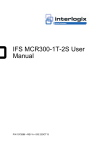
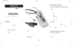
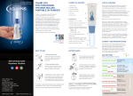
10/100/1000Base-T to Dual 1000Base-X SFP Media Converter GT-1205A User’s Manual Trademarks Copyright © PLANET Technology Corp. 2011. Contents subject to which revision without prior notice. PLANET is a registered trademark of PLANET Technology Corp. All other trademarks belong to their respective owners. Disclaimer PLANET Technology does not warrant that the hardware will work properly in all environments and applications, and makes no warranty and representation, either implied or expressed, with respect to the quality, performance, merchantability, or fitness for a particular purpose. PLANET has made every effort to ensure that this User’s Manual is accurate; PLANET disclaims liability for any inaccuracies or omissions that may have occurred. Information in this User’s Manual is subject to change without notice and does not represent a commitment on the part of PLANET. PLANET assumes no responsibility for any inaccuracies that may be contained in this User’s Manual. PLANET makes no commitment to update or keep current the information in this User’s Manual, and reserves the right to make improvements to this User’s Manual and/or to the products described in this User’s Manual, at any time without notice. If you find information in this manual that is incorrect, misleading, or incomplete, we would appreciate your comments and suggestions. FCC Warning This device has been tested and found to comply with the limits for a Class B digital device, pursuant to Part 15 of the FCC Rules. These limits are designed to provide reasonable protection against harmful interference when the equipment is operated in a commercial environment. This equipment generates, uses, and can radiate radio frequency energy and, if not installed and used in accordance with the Instruction manual, may cause harmful interference to radio communications. Operation of this equipment in a residential area is likely to cause harmful interference in which case the user will be required to correct the interference at whose own expense. CE Mark Warning This is a Class B product. In a domestic environment, this product may cause radio interference, in which case the user may be required to take adequate measures. Energy Saving Note of the Device This power required device does not support Standby mode operation. For energy saving, please remove the DC-plug to discon-nect the device from the power circuit. Without removing the DC-plug or switch off the device, the device will still consume power from the power source. In the view of Saving the Energy and reduce the unnecessary power consuming, it is strongly suggested to power off or to remove the DC-plug for the device if this device is not intended to be active. WEEE Warning To avoid the potential effects on the environment and human health as a result of the presence of hazardous substances in electrical and electronic equipment, end users of electrical and electronic equipment should understand the meaning of the crossed-out wheeled bin symbol. Do not dispose of WEEE as unsorted municipal waste and have to collect such WEEE separately. Revision PLANET Gigabit Ethernet Redundant Media Converter User’s Manual FOR MODEL: GT-1205A Revision: 1.0 (Augest, 2011) Part No.: 2350-AA4530-000 Table of Contents 1. Introduction...................................................................... 5 1.1 Check List................................................................... 5 1.2 Introduction To GT-1205A............................................. 5 1.3 Key Features............................................................... 6 2. Product Specification.......................................................... 6 2.1 Functional Specifications............................................... 6 2.2 LED Indicator.............................................................. 7 3. Installation........................................................................ 8 3.1 Product Outlook........................................................... 8 3.2 Stand-alone Installation................................................ 9 3.3 Chassis Installation And Rack Mounting....................... 11 3.4 Din-Rail Installation.................................................... 11 4. Appendix A..................................................................... 12 A.1 Device’s RJ-45 Pin Assignments.................................. 12 A.2 RJ-45 Cable Pin Assignment....................................... 12 A.3 Fiber Optical Cable Connection Parameter.................... 13 A.4 Power Information..................................................... 14 A.5 Available Modules...................................................... 15 1. Introduction 1.1 Check List Check the contents of your package for following parts: ll GT-1205A x 1 ll 5V / 2A AC-DC Power Adapter x 1 ll User’s Manual x 1 Note GT-1205A is with two vacant SFP module slot. The 1000Base-X SFP module is not bundled with in the package 1.2 Introduction To GT-1205A Thank you for choosing the 10/100/1000Base-T 1000Base-X SFP Media Converter. to Dual The GT-1205A is a 3-Port Media Converter which supports conversion between 10/100/1000Base-T and 1000Base-X network. Different with the other one-port channel media converter, the Media Converter is designed for critical networks that require fiber or copper link, such as ISP, telecom, hospital, banking and enterprise. PLANET 3-Port Gigabit Media converter is shown as following: With the 3-Port switch mode, they work in high performance Store and Forward mechanism; also can prevent packet loss with IEEE 802.3x Flow Control (Full-Duplex) and Back Pressure (Half-Duplex). With 1000Base-X SFP ports, the GT-1205A is with high reliability and flexibility to extend the distance up to 550m, 10Km, 20Km, or longer. The Media Converter can be used as a stand-alone unit or as a slide-in module to the PLANET Media Converter Chassis (MC-700 and MC-1500 series), it could be hot swappable in MC-Chassis. 5 1.3 Key Features Standard ll Complies with IEEE 802.3, IEEE 802.3u, IEEE 802.3ab 10/100/1000Base-T, IEEE 802.3z, 1000Base-SX / LX ll IEEE 802.3x Full-Duplex Flow-Control, Back-Pressure in Half-Duplex eliminate packets loss Interface ll Dual 1000Base-SX / LX SFP Fiber optic, One 10/100/1000Base-T Copper ll Auto-Negotiation for 10/100Base-TX Half-Duplex or 10/100/1000Base-T Full-Duplex ll Auto MDI/MDI-X Mechanical ll 5V/2A DC power supply ll LED indicators for easy network diagnose ll Co-work with PLANET MC family Media Chassis (MC-700/1500/1500R/1500R48) 2. Product Specification 2.1 Functional Specifications Model Ports Optic Interface 6 GT-1205A Copper 1 x 10/100/1000Base-T port Fiber 2 x 1000Base-X SFP interfaces SFP Twisted-pair 10Base-T: 2-Pair UTP CAT. 3, 4, 5, up to 100 meter 100Base-TX: 2-Pair UTP CAT. 5, 5e up to 100 meter 1000Base-T: 4-Pair UTP CAT. 5e, 6 up to 100 meter Fiber-optic cable 50/125μm or 62.5/125μm multi-mode fiber cable, up to 220 & 550 meters 9/125μm single-mode cable, provide long distance for 10/15/20/30/40/50/60/70/120km or longer (vary on SFP module) Cable Switch Processing Scheme Store-and-Forward Switching Fabric 6Gbps / non-blocking LED indicator System: One Power LED TP Port: One Speed, One LNK/ACT Fiber Port: Two LNK/ACT Dimension (W x D x H) 94 x 70 x 26 mm Weight 191g (device only) Power Requirement 5V DC, 2A max. Power Consumption 5.4Watts / 18.5 BTU per hour max. Standards IEEE IEEE IEEE IEEE IEEE 802.3, 10Base-T 802.3u, 100Base-TX 802.3ab, 1000Base-T 802.3z, 1000Base-SX / LX 802.3x, Flow Control 2.2 LED Indicator The LED indicators give you instant feedback on status of the converter: 7 System LED PWR Color Green Function Lit: Power on. GT-1205A -10/100/1000Base-T Port LED 1 2 Color Green Green Function Lit Indicate that the fiber optical port is link up. Blink Indicate that the converter is actively sending or receiving data over that port. Off Indicate that the fiber optical port is link down. Lit Indicate that the fiber optical port is link up. Blink Indicate that the converter is actively sending or receiving data over that port. Off Indicate that the fiber optical port is link down. Lit Indicate that the copper port is link up. LNK/ Indicate that the converter is actively sending Orange Blink ACT or receiving data over that port. Off Indicate that the copper port is link down. Lit Indicate that the copper port is operating at 1000Mbps. Off Indicate that the copper port is link down or 10/100Mbps. 1000 Green 3. Installation 3.1 Product Outlook Front Panel 8 ll Port-1 1000Base-X SFP slot ll Port-2 1000Base-X SFP slot ll Port-3 10/100/1000Base-T copper connector Rear Panel ll One DC jack for DC 5V / 2A power input. 3.2 Stand-alone Installation GT-1205A is with high reliability and flexibility to extend the distance up to 550m and 10/15/20/30/40/50/60/70/120km. It depends on the 1000Base-SX / LX SFP transceiver modules. The SFP transceiver is hot-pluggable and hot-swappable. You can plug-in and out the transceiver to / from any SFP port without having to power down the converter. To install a GT-1205A stand-alone, on a desktop or shelf, simply complete the following steps: Step 1: Turn off the power of the device/station in a network to which the GT-1205A will be attached. Step 2: Ensure that there is no activity in the network. Step 3: Slot in the 1000Base-X SFP. Make sure both side of the SFP transceiver are with the same media type, for example: 1000Base-SX / 550m multi-mode to 1000Base-SX / 550m multi-mode, 1000Bas-LX / 10km single mode to 1000Base-LX / 10km single mode. 9 1000Base-X SFP Transceiver 10/100/1000Base-T UTP 1000Base-X LC Fiber 1000Base-X LC Fiber 5V DC power Figure 3-1: GT-1205A Media Converter Stand Alone Installation Step 4: Connect the fiber cable. Attach the duplex LC connector on the network cable into the SFP transceiver. Step 5: Attach fiber cable from the GT-1205A to the fiber network. TX, RX must be paired at both ends. Step 6: Connect the 5V DC power adapter to the GT-1205A and verify that the Power LED lights up. Step 7: Turn on the power of the device/station; the LINK LED should light when all cables are well attached. Note 10 1. It is recommends using PLANET MGB series SFP modules for the converter. If you insert a SFP trans-ceiver that is not supported, the converter will not recognize it. Please check appendix or go visit our WEB site for details specification information. http://www.planet.com.tw 2. To prevent from optic acceptor malfunction, check the both wires / transmitter before power on the con-verter. 3. To remove the SFP module, please remove the fiber connectors in advanced and push the belt or letch of the module. Pull out the module with violent may damage the module and the converter. 3.3 Chassis Installation And Rack Mounting To install the media converter in a 10-inch or 19-inch with standard rack, follow the steps described below. Step 1: Find an available slot from your PLANET MC Chassis. Step 2: Follow Figure 3-2, carefully slide in the converter fully and firmly fitted to the slot of the chassis. The Power LED of the converter will turns ON. Note Figure 3-2: Insert GT-1205A Media Converter into an available slot 1. Never push the converter into the slot with violent, it could damage the chassis. 2. The Media Converter Chassis supports hotswap, there is no need to turn off the whole chassis before slide in the new converter. 3.4 Din-Rail Installation The GT-1205A also supports din-rail installation, the option kit RKE-DIN can help to mount the converter to the Rail system, please follow the steps below. Step 1: Use the bundled screw to fix the RKE-DIN to the converter. Step 2: Hook the converter to the DIN-Rail. Note You must use the screws supplied with the RKE-DIN. Damage caused to the parts by using incorrect screws would invalidate your warranty. 11 4. Appendix A A.1 Device’s RJ-45 Pin Assignments 1000Mbps, 1000Base T RJ-45 Connector pin assignment Contact MDI MDI-X Contact 1 BI_DA+ BI_DB+ 5 BI_DC- MDI BI_DD- MDI-X 2 BI_DA- BI_DB- 6 BI_DB- BI_DA- 3 BI_DB+ BI_DA+ 7 BI_DD+ BI_DC+ 4 BI_DC+ BI_DD+ 8 BI_DD- BI_DC- 10/100Mbps, 10/100Base-TX RJ-45 Connector pin assignment Contact MDI Media Dependant Interface MDI-X Media Dependant Interface-Cross 1 Tx + (transmit) Rx + (receive) 2 Tx - (transmit) Rx - (receive) 3 Rx + (receive) Tx + (transmit) 4, 5 6 7, 8 Not used Rx - (receive) Tx - (transmit) Not used A.2 RJ-45 Cable Pin Assignment The standard RJ-45 receptacle/connector There are 8 wires on a standard UTP/STP cable and each wire is color-coded. The following shows the pin allocation and color of straight cable and crossover cable connection: 12 Straight Cable 1 2 3 4 5 6 7 8 SIDE 1 1 2 3 4 5 6 7 8 SIDE 2 SIDE 1 1 = White/Orange 2 = Orange 3 = White/Green 4 = Blue 5 = White/Blue 6 = Green 7 = White/Brown 8 = Brown SIDE 2 1 = White/Orange 2 = Orange 3 = White/Green 4 = Blue 5 = White/Blue 6 = Green 7 = White/Brown 8 = Brown SIDE 1 SIDE 2 1 = White/Green 2 = Green 3 = White/Orange 4 = Blue 5 = White/Blue 6 = Orange 7 = White/Brown 8 = Brown Cross Over Cable 1 2 3 4 5 6 7 8 SIDE 1 1 2 3 4 5 6 7 8 SIDE 2 1 = White/Orange 2 = Orange 3 = White/Green 4 = Blue 5 = White/Blue 6 = Green 7 = White/Brown 8 = Brown Figure A-1: Straight-Through and Crossover Cable Please make sure your connected cables are with same pin assignment and color as above picture before deploying the cables into your network. A.3 Fiber Optical Cable Connection Parameter The wiring details are as below: Fiber Optical patch Cables: Diameter (micron) Modal Max. Bandwidth Distance (MHz * km) (meters) 1000Base-SX Multi-mode 62.5 62.5 50 50 100 200 400 500 220 275 500 550 62.5 50 50 5 4 5 550 Multi-mode N/A 5000* Standard 1000Base-LX Fiber Single-mode 9 13 Note The IEEE 1000Base-LX standard supports up to 5000 meters, however, with various SFP modules the actual link distance may vary. Please check appendix for the available modules. A.4 Power Information The power jack of the Gigabit Media Converter is with 2.5mm in the central post and required +5V DC power input. It will conform to the bundled AC-DC adapter and PLANET’s Media Chassis. If you have issue to make the power connection, please contact with your local sales dealer. Please keep the AC-DC adapter as spare parts when your Media Converter is installed to a Media Chassis. 2.5mm DC Receptacle 2.5mm +5V for each slot DC receptacle is 2.5mm wide that conforms to and matches the Media Converter 2.5mm DC jack’s central post. Do not install any improper unit, model of the Media Converter 14 A.5 Available Modules The following list the available Modules for GT-1205A MGB-GT SFP-Port 1000Base-T mini-GBIC module MGB-SX SFP-Port 1000Base-SX mini-GBIC module 550meters MGB-LX SFP-Port 1000Base-LX mini-GBIC module - 10km MGB-L30 SFP-Port 1000Base-LX mini-GBIC module - 30km MGB-L50 SFP-Port 1000Base-LX mini-GBIC module - 50km MGB-L70 SFP-Port 1000Base-LX mini-GBIC module - 70km MGB-L120 SFP-Port 1000Base-LX mini-GBIC module - 120km MGB-LA10 SFP-Port 1000Base-LX mini-GBIC module LC WDM (TX: 1310nm), SM, 10km MGB-LB10 SFP-Port 1000Base-LX mini-GBIC module LC WDM (TX: 1550nm), SM, 10km MGB-LA20 SFP-Port 1000Base-LX mini-GBIC module LC WDM (TX: 1310nm), SM, 20km MGB-LB20 SFP-Port 1000Base-LX mini-GBIC module LC WDM (TX: 1550nm), SM, 20km MGB-LA40 SFP-Port 1000Base-LX mini-GBIC module LC WDM (TX: 1310nm), SM, 40km MGB-LB40 SFP-Port 1000Base-LX mini-GBIC module LC WDM (TX: 1550nm), SM, 40km MGB-TSX SFP-Port 1000Base-SX mini-GBIC module 550meters (-40~75°C) MGB-TLX SFP-Port 1000Base-LX mini-GBIC module - 10km (-40~75°C) MGB-TL30 SFP-Port 1000Base-LX mini-GBIC module - 30km (-40~75°C) MGB-TL70 SFP-Port 1000Base-LX mini-GBIC module - 70km (-40~75°C) 15 EC Declaration of Conformity For the following equipment: *Type of Product *Model Number : 10/100/1000Base-T to Dual 1000Base-X SFP Media Converter (1 TP, 2 SFP) GT-1205A : * Produced by: Manufacturer‘s Name : Planet Technology Corp. Manufacturer‘s Address : 10F., No.96, Minquan Rd., Xindian Dist., New Taipei City 231, Taiwan (R.O.C.). is herewith confirmed to comply with the requirements set out in the Council Directive on the Approximation of the Laws of the Member States relating to Electromagnetic Compatibility Directive on (2004/108/EC). For the evaluation regarding the EMC, the following standards were applied: EN 55022 EN 61000-3-2 EN 61000-3-3 EN 55024 IEC 61000-4-2 IEC 61000-4-3 IEC 61000-4-4 IEC 61000-4-5 IEC 61000-4-6 IEC 61000-4-8 IEC 61000-4-11 (CLASS A: 2006 + A1:2007) (2006 + A2:2009) (2008) (1998+A1:2001+A2:2003) (2008) (2008) (2004) (2005) (2008) (2009) (2004) Responsible for marking this declaration if the: Manufacturer Authorized representative established within the EU Authorized representative established within the EU (if applicable): Company Name: Planet Technology Corp. Company Address: 10F., No.96, Minquan Rd., Xindian Dist., New Taipei City 231, Taiwan (R.O.C.) Person responsible for making this declaration Name, Surname Kent Kang Position / Title : Product Manager Taiwan Place 30, Sep., 2011 Date Legal Signature PLANET TECHNOLOGY CORPORATION e-mail: [email protected] http://www.planet.com.tw 10F., No.96, Minquan Rd., Xindian Dist., New Taipei City, Taiwan, R.O.C. Tel:886-2-2219-9518 Fax:886-2-2219-9528