1
November, 7th 2004
Version 001.0
Peter Göttlicher
DESY-FEB
Fast Pulse Masker
– User manual –
Abstract:
For beam studies at VUVFEL it is required to kick out individual bunches. For these
short time periods signals from a few photomultiplier has to be disabled. The basic
functionalities of the electronics are:
- Masking the signal for a period of 500ns after a rising edge of a TTL-input
- Forbidding a second trial of masking during the next 90ms
- Keeping the mean level of the input signal from the period (t=3.3ms) before the
masking during the short term of the masking.
- Slow drifting of the output to a 20mV level with opposite polarity, if a failure in
the digital electronics keeps the masking for long periods.
- (Pseudo-) differential analogue input to avoid ground loops,
- Differential analogue output with gain 1, to reduce common mode currents and to
keep the difference small between plugging the ‘Fast-pulse-masker’ into the cable
from the photo multiplier to the following electronics or leaving it out.
- 100 W differential techniques for usage of LAN cables or twisted pair flat cables.
Outline:
1.
2.
3.
4.
The Crate
The Gate_and_Busy_Logic
The Analogue Board: The Analog_Pulse_Masker
Summary of Parameters and Pulse sequences
Page 1 of 16
November, 7th 2004
Version 001.0
Peter Göttlicher
DESY-FEB
Page 2 of 16
November, 7th 2004
Version 001.0
Peter Göttlicher
DESY-FEB
1. The Crate
The crate has to be supplied with the analogue signal from the PMT’s or any other
(pseudo-)differential signal source and a digital pulse, which starts the period,
during which the analogue input is masked out.
The digital behaviour of the gating is described in chapter 2.
The analogue functionality is described in chapter 3.
Chapter 4 summarises the basic parameters and contains examples of pulse
sequences.
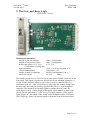
The construction is made around a standard 3-HE Euro-Crate, which houses:
- the cabling – halogen free.
- a power supply for +15V and -15V, Kniehl: CPM 101/PFS , DESY: 27168
- One board “Gate and Busy logic”, DESY board: 7760-00
- Up to 5 boards “Pulse_masker_analog”, each handling a single analogue
channel, DESY board 7750-00
Only half of the crate is in use. The rest can be equipped with other upgrade
projects.
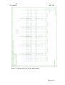
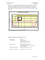
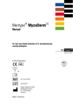
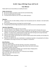
The cabling is summarized in picture 1.1 . This picture includes also the ferrites to
reduce the ripple from the switching power supply near to the power supply itself.
Since the crate is needed only once, the backbone is set up by wires and power
bars. The backbone distributes the power ("15V) to each slot and connects the
pulse for masking between all slots in a differential mode (RS422). The masking
pulse has to be driven through the backbone from slot 2 with the module “Gate
and busy Logic”. The analogue boards can be installed into the slots 3 to 7. From
these five slots the analogue inputs and outputs are wired to the connectors on the
rear side of the crate following the connectors and pin-configuration of the beamloss-monitor:
sub-D 9-pol,
input is male, output is female
pin 1 is positive input, pin 6 negative input
pin 9 is shield (close to GND)
cables eith 100W-impedance are used for the analogue signals.
Details of the signal behaviours are described on the involved boards in the next
chapters. Pulse sequences are illustrated afterwards in chapter 4.
Page 3 of 16
November, 7th 2004
Version 001.0
Peter Göttlicher
DESY-FEB
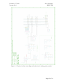
Figure 1.1: Wiring of the crate for the “Pulse masker”
Page 4 of 16
November, 7th 2004
Version 001.0
Peter Göttlicher
DESY-FEB
2. The Gate_and_Busy_Logic
PCB: DESY 7760-00
Fundamental parameter:
Length of gate for masking:
Length of busy and veto time:
Rising edge detect (Vlow, Vhigh)
Configurable to falling edge
Input impedance
Current comsumption
Output of mask to backplane
Quiescent current
500ns (configurable)
90ms (configurable)
0.5V, 2.1V
10pF, 1mA at true low/high level
15mA from +15V
RS422 with impedance 100 W
@+15V
20mA
The module responses on a TTL-level input pulse from a LEMO-connector on the
front panel. This signal is supplied to the internal circuit with high impedance. A
second LEMO-connector allows a passive daisy-chain to other modules or a
termination with 50W. After a detection of a rising edge the module changes into
the busy state and sends the masking signal for the time tmask to the backplane
connector. The length of the masking signal is configured to be 500ns. By
replacing R1, R16 or C14 the length of the signal can be adapted to other needs
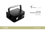
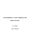
(check with the data sheet of 74-HCT-221). The logic sequence of the applied
input “trigger in” , the output of the “mask”to the backplane and the front panel
LED “illegal try” and a few internal signals is sketched in the following picture:
Page 5 of 16
November, 7th 2004
Version 001.0
Peter Göttlicher
DESY-FEB
The busy state keeps for an internally set time period. As default after delivery the
board is configured to 90ms. It can be configured by a monostable multivibrator
or a more accurate oscillator based timing circuit followed by a divider. The
second solution is the default setting at time of production and for long periods the
more stable solution. The busy time can be configured by the following jumpers
and the following formula:
Tbusy = 100ns C (n - s/2) C m C 10k
‘m’ and ‘k’ are defined by the chip ‘8640BN’, which divides the base
frequency of 10MHz by the factors m and 10k :
m
1
2
3
4
5
6
10
12
LB14
open
open
open
close
close
close
open
close
LB15
open
close
close
open
open
close
open
close
LB16
open
open
close
open
close
open
close
close
k
1
2
3
4
5
6
7
8
9
LB19
open
open
open
open
close
close
close
open
close
LB17
open
open
close
close
open
open
close
open
close
LB18
open
close
open
close
open
close
open
close
close
Page 6 of 16
November, 7th 2004
Version 001.0
Peter Göttlicher
DESY-FEB
‘s’ is set by jumper
LB1
closed from 2 to 3 : s=1 (default)
closed from 1 to 2 : s=0
Technically it decides between rising and falling edge of the
signal produced by the divider (8640BN)
‘n’ is set by closed one and only one jumper out of the following list.
This is realized by a shift register, which divides the frequency
after the 8640BN by the number of used flip-flops by querying
the nth register to get .true. :
LB4 n=1 (only allow, if LB1 is closed from 2 to 3)
LB5 n=1
LB6 n=2
LB7 n=3
LB8 n=4
LB9 n=5
LB10 n=6
LB11 n=7
LB12 n=8 (default)
LB13 used monostable multivibrator instead
The remaining jumpers have the following meaning:
LB2 closed from 1 to 2 (standard): Mask the time interval tmask
closed from 2 to 3 : Mask all the time except the interval tmask
LB3 closed from 1 to 2 : Use rising edge to trigger the masking
closed from 2 to 3: Use falling edge to trigger the masking
LB20 closed (default): The second LEMO connector allows the
daisy-chain/termination otherwise the second LEMO
connector is not connected at all.
LB21 closed (default): The shield from the LEMO is connected to electronic
ground. Open avoids a ground loop, but reply on an
other ground connection to the pulse source.
LB22 no function , just solder points
The status of the module is indicated by three LED’s on the front panel:
green
Power is supplied (+15V)
yellow
A edge for the masking is detected and the module is in the
‘busy’-state
red
A second edge for masking is detected while the module is in
the ‘busy’-state. The LED is kept on until the ‘busy’-state
ends.
Page 7 of 16
November, 7th 2004
Version 001.0
Peter Göttlicher
DESY-FEB
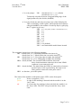
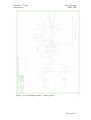
Picture 2.1 : Top level diagram for the Gate and Busy logic
Page 8 of 16
November, 7th 2004
Version 001.0
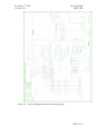
Picture 2.2 :
Peter Göttlicher
DESY-FEB
Circuit diagram for the block “Power” (2) in the
“Gate and Busy logic”
Page 9 of 16
November, 7th 2004
Version 001.0
Peter Göttlicher
DESY-FEB
3. The Analogue Board: Analogue pulse masker
PCB: DESY 7752-00
Basic parameters:
Analogue input signal:
Analogue output signal:
Digital input (mask)
Quiescent power
additional
Pseudo-Differential
100W differential termination
common mode: -7V to +5V
differential: "5.4V
Differential "5.4V into 100W
Rise/fall times: 10ns
Delay: 3.3ns from electronic card
(5ns together with cables in crate)
RS422 level
@+15V
90mA
@-15V
70mA
50mA for drive of 5V input 100W.
All signal input and outputs are located on the backplane connector.
The digital input switches between a usual mode and the masking mode.
In the ‘usual mode’ the input is driven to the output, keeping the differential gain
close to 1, but rejecting the common mode.
In the ‘masking mode’ the level of the convolution of the input with a exponential
function e(-t/t) with t=3.3ms before switching to the masking is kept. With a
longer time constant of 33ms the output drifts to a differential 20ms, opposite to
the expected input signal polarity. This allows to cause in the VUVFEL-BLM
system to gives alarms via the HV-channel, if electronic faults causes long
masking periods.
Page 10 of 16
November, 7th 2004
Version 001.0
Peter Göttlicher
DESY-FEB
The output is configured to drive a 100W cable. For this a backward termination is
applied.
On the front panel the status of both supply voltages are displayed and during the
masking period a lightened red LED indicates that status. For short pulses the
period of illuminating is elongated to eye visible periods.
green +15V
yellow -15V
red
masking active
Page 11 of 16
November, 7th 2004
Version 001.0
Peter Göttlicher
DESY-FEB
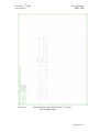
Figure 3.1: Top level of the circuit diagram for the board ‘Analog_pulse_masker’
Page 12 of 16
November, 7th 2004
Version 001.0
Peter Göttlicher
DESY-FEB
Figure 3.2: Circuit diagram of the block 2 “Power”
Page 13 of 16
November, 7th 2004
Version 001.0
Peter Göttlicher
DESY-FEB
Figure 3.3: Circuit diagram of the 3 “Analog_chain”
Page 14 of 16
November, 7th 2004
Version 001.0
Peter Göttlicher
DESY-FEB
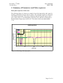
4. Summary of Parameters and Pulse sequences
Basic pulse sequences of the crate:
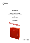
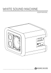
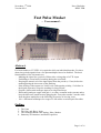
The following figure 4.1 shows an example of two fast input pulses and a gate for
masking, which starts between the two pulses. The analogue signals are measured
with a differential probe. This picture illustrates that the first pulse passes with a
gain 1 and a delay of 3.3ns through the electronic card, while the second pulse is
masked and the output stays close to 0V. The cables of the crate adds another
1.7ns
making pulses
6
input
output
gate
voltage diff [V]
4
2
0
-2
-4
-6
0
50
100
150
200
time [ns]
Figure 4.1: Masking a fast input pulse
Page 15 of 16
November, 7th 2004
Version 001.0
Peter Göttlicher
DESY-FEB
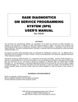
In picture 4.2 a long input pulse together with a DC-level is applied to the input.
During the masking period of 500ns after the rising edge the DC-level is kept
while the pulse amplitude is masked out. After the 500ns the level of the long
pulse reappears. This plot includes the delays of the electronic card and the cables
of the crate.
masking part of long pulse
6
4
voltage diff [V]
input
output
2
gate
0
-2
-4
-6
0.0
200.0
400.0
600.0
800.0
time [ns]
Figure 4.2: Masking of a single long input pulse
The basic parameters of the complete crate are:
Power supply :
analogue input:
230V AC
differential "5.4V
common mode –7V to +5V
differential impedance 100W
analogue output:
maximum output swing:
differential gain 1 into 100W
differential output "5.4V in linear range.
common mode 0V
single ended without load "10V.
gate input for masking:
rising edge from <0.5V to > 2.1V
Page 16 of 16