1
Wireless 802.11 B/G/N
ADSL2/2+ Modem Router
User Manual
Contents
1.
2.
3.
Introduction..........................................................................................................3
1.1
General Description .................................................................................3
1.2
Specifications ............................................................................................3
1.2.1
ADSL Standard ............................................................................3
1.2.2
Wireless Features .........................................................................3
1.2.3
Software Features ........................................................................3
1.2.4
Management .................................................................................3
Hardware Installation .........................................................................................4
2.1
Packet content ..........................................................................................4
2.2
Hardware Setup Procedures ...................................................................4
Software Configuration .......................................................................................5
3.1
Quick Start................................................................................................6
3.2
Interface Setup .......................................................................................10
3.2.1
Internet Settings .........................................................................10
3.2.2
LAN Settings...............................................................................11
3.2.3
Wireless LAN Settings ...............................................................13
3.3
Advanced Setup......................................................................................15
3.3.1
Firewall .......................................................................................15
3.3.2
Routing........................................................................................15
3.3.3
NAT .............................................................................................16
3.3.4
QoS (Quality of Service).........................................................18
3.3.5
VLAN ..........................................................................................20
3.3.6
ADSL...........................................................................................21
3.4
Access Management...............................................................................21
3.4.1
ACL .............................................................................................21
3.4.2
IP Filter .......................................................................................22
3.4.3
SNMP ..........................................................................................23
3.4.4
UPnP............................................................................................23
3.4.5
DDNS...........................................................................................24
3.4.6
CWMP ........................................................................................24
3.5
Maintenance ...........................................................................................25
3.5.1
Administration ...........................................................................25
3.5.2
Time Zone ...................................................................................25
3.5.3
Firmware ....................................................................................25
3.5.4
SysRestart ...................................................................................26
3.5.5
Diagnostics ..................................................................................26
3.6
Status .......................................................................................................27
3.6.1
Device Info ..................................................................................27
3.6.2
System Log..................................................................................28
3.6.3
Statistics ......................................................................................28
1. Introduction
1.1 General Description
The ADSL2+ Wireless Router is a high-speed ADSL2+ Ethernet/Wireless router that is
specifically designed to connect to the Internet and to directly connect to your local area
network (LAN) via high-speed 10/100 Mbps Ethernet, or wireless LAN (WLAN). The
ADSL2+ modem is compatible with the latest ADSL standards, including ADSL2 and
ADSL2+, and supports up to 24 Mbps downstream and 1.5 Mbps upstream to deliver true
broadband speed and throughput. The DSL router supports wireless 802.11b/g/n and the
following security protocols: WEP, WPA, WPA2, and PSK. To ensure fully compatibility, the
DSL device was tested with all major DSLAMs, and support standard 10/100 Mbps Base-T
Ethernet interface Auto MDI/MDIX 10/100 Switch function allowing user easily to link to PC
or other Switches/Hubs. The DSL device is an idea solution for multi-users utilizing build-in
channel mode (PPPoE, PPPoA, IPoA, RFC1483), IP routing, NAT functionalities sharing the
ADSL link. The DSL device is also a perfect solution for the residential users, it supports the
users with bridge mode in host based PPPoE Client.
1.2 Specifications
1.2.1
ADSL Standard
ITU-T G.992.1(G.dmt)
ANSI T1.413 Issue 2
G.992.2 (G.lite)
G.994.1 (G.hs)
Auto-negotiating rate adaptation
ADSL2 G.dmt.bis (G.992.3)
ADSL2 G.lite.bis (G.992.4)
ADSL2+ (G.992.5)
1.2.2
Wireless Features
Compliant with IEEE 802.11 B/G/N
Up to 150 Mbps wireless operation rate
64/128 bits WEP for security
WPA support
ACL (MAC address Filtering)
1.2.3
Software Features
RFC-1483/2684 LLC/VC-Mux bridged/routed mode, RFC-1577 Classical IP over ATM,
RFC-2516 PPPoE, RFC-2364 PPPoA, ITU-T 1.610 F4/F5 OAM send and receive loop-back,
802.1d Spanning-Tree Protocol, DHCP Client/Server/Relay ,NAT, RIP v1/v2, DNS Relay
Agent, DMZ support, IGMP Proxy/Snooping, Stateful Packet Inspection, IP Packet Filtering ,
QoS, Dynamic DNS, UPnP support.
1.2.4
Management
Web-based Configuration Menu-driven Command-line Interpreter Telnet Remote
Management SNMP v1/v2/Trap Firmware upgrade through FTP, TFTP and HTTP
Configuration backup/restore Diagnostic Tool
2. Hardware Installation
2.1 Packet content
ADSL2+ Router * 1
Dedicated Power Adaptor *1
RJ-45 Ethernet cable*1
RJ-11 telephone cable*1
Manual CD*1
Antenna*1
2.2 Hardware Setup Procedures
1. Connect RJ-11 line from ADSL2+ Wireless Router WAN port to DSLAM.
2. Connect the SMA from Antenna.
3. Connect RJ-45 line from your PC to ADSL2+ Wireless Router LAN1-4 port.
4. Connect the Power Adaptor from power jack to power outlet.
5. Push the power switch in “ON” mode.
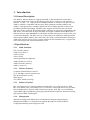
3. Software Configuration
The DSL device is an ADSL2+ wireless router. When you power on the device, the system
will boot up and connect to ADSL automatically. The default configurations for the system
are listed below.
LAN IP address: 192.168.1.1,
NetMask:255.255.255.0
Wireless SSID: ADSL_Modem_Router
User can change settings via WEB browser. The following sections describe the set up
procedures. Please set your PC’s Ethernet port as follow:
IP address: 192.168.1.XXX
NetMask:255.255.255.0
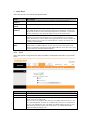
Start your web browser. Type the Ethernet IP address of the modem/router on the address bar
of the browser. Default IP address is 192.168.1.1. The Enter Network Password dialog box
appears. Type the user name and password and then click OK.(default user name : admin;
default password : admin) Once you have connected to ADSL2+ router. You will see the
status page.
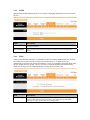
This page displays the ADSL modem/router’s current status and settings.
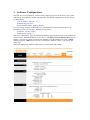
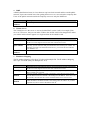
3.1 Quick Start
The Quick Start Wizard is a useful and easy utility to help setup the device to quickly connect
to your ISP (Internet Service Provider) with only a few steps required. It will guide you step
by step to configure the password, time zone, and WAN settings of your device. The Quick
Start Wizard is a helpful guide for first time users to the device.
¾ Click RUN WIZARD to move on:
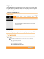
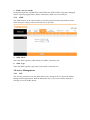
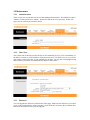
¾ Run Wizard
The Wizard will guide you through these four quick steps. Begin by clicking on NEXT.
Step 1. Set your new password
Step 2. Choose your time zone
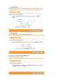
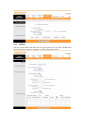
Step 3. Set your Internet connection
a. Dynamic IP Address
Choose this option to obtain an IP address automatically from your ISP.
b. Static IP Address
Choose this option to set static IP information provided to you by your ISP.
c. PPPoE/PPPoA
Choose this option, if your ISP uses PPPoE/PPPoA. (For most DSL users)
d. Bridge Mode
Choose this option, if your ISP uses Bridge Mode.
Step 4. Save settings of this ADSL Router
Click NEXT to save the settings
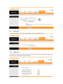
3.2 Interface Setup
3.2.1
Internet Settings
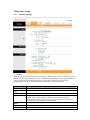
a. ATM VC
ATM settings are used to connect to your ISP. Your ISP provides VPI, VCI settings to you. In
this Device, you can totally setup 8 VCs on different encapsulations, if you apply 8 different
virtual circuits from your ISP. You need to activate the VC to take effect. For PVCs
management, you can use ATM QoS to setup each PVC traffic line's priority.
Item
Description
Virtual Circuit
Select the VC number you want to setup.
VPI
Virtual Path Identifier.
VCI
Virtual Channel Identifier.
ATM QoS
Select the Quality of Service types for this Virtual Circuit. The ATM QoS types
include CBR (Constant Bit Rate), VBR (Variable Bit Rate) and UBR
(Unspecified Bit Rate). These QoS types are all controlled by the parameters
specified below, including PCR, SCR and MBS.
PCR
Peak Cell Rate.
SCR
Sustained Cell Rate.
MBS
Maximum Burst Size.
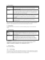
b. Encapsulation
Item
Description
Select this option if your ISP provides you an IP address automatically. This
Dynamic IP
Static IP
PPPoA/PPPoE
Bridge Mode
option is typically used for Cable services. Please enter the Dynamic IP
information accordingly.
Select this option to set static IP information. You will need to enter in the
Connection type, IP address, subnet mask, and gateway address, provided to you
by your ISP. Each IP address entered in the fields must be in the appropriate IP
form, which is four IP octets separated by a dot (x.x.x.x). The Router will not
accept the IP address if it is not in this format.
Select this option if your ISP requires you to use a PPPoE connection. This
option is typically used for DSL services. Select Dynamic PPPoE to obtain an IP
address automatically for your PPPoE connection. Select Static PPPoE to use a
static IP address for your PPPoE connection. Please enter the information
accordingly.
The modem can be configured to act as a bridging device between your LAN
and your ISP. Bridges are devices that enable two or more networks to
communicate as if they are two segments of the same physical LAN. Please set
the Connection type.
c. NAT
Select this option to Activate/Deactivated the NAT (Network Address Translation) function
for this VC. The NAT function can be activated or deactivated per PVC basis.
d. Default Route
If enable this function, the current PVC will be the default gateway to internet from this
device.
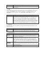
e. Dynamic Route
Item
Description
Select
this option to specify the RIP version,
RIP
(Routing
Information
protocol)
RIP Direction
including RIP-1, RIP-2M and RIP-2B. RIP-2M and RIP-2B are both sent in
RIP-2 format; the difference is that RIP-2M using Multicast and RIP-2 using
Broadcast format.
Select this option to specify the RIP direction. None is for disabling the RIP
function. Both means the ADSL Router will periodically send routing
information and accept routing information then incorporate into routing
table. IN only means the ADLS router will only accept but will not send RIP
packet. OUT only means the ADLS router will only send but will not accept
RIP packet.
f. Multicast
IGMP (Internet Group Multicast Protocol) is a session-layer protocol used to establish
membership in a multicast group. The ADSL ATU-R supports IGMP version 1
(IGMP-v1), IGMP-v2 and IGMP-v3. Select Disabled to disable it.
g. MAC Spoofing
Internet MAC Spoofing.
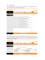
3.2.2
LAN Settings
These are the IP settings of the LAN interface for the device. These settings may be referred
to as Private settings. You may change the LAN IP address if needed. The LAN IP address is
private to your internal network and cannot be seen on the Internet.
a. DHCP Server
DHCP stands for Dynamic Host Control Protocol. The DHCP Server gives out IP addresses
when a device is booting up and request an IP address to be logged on to the network. That
device must be set as a DHCP client to obtain the IP address automatically. By default, the
DHCP Server is enabled. The DHCP address pool contains the range of the IP address that
will automatically be assigned to the clients on the network.
Item
Starting IP
Address
IP Pool Count
Lease Time
Description
The starting IP address for the DHCP server's IP assignment.
The max user pool size.
The length of time for the IP lease.
b. DHCP Relay
A DHCP relay is a computer that forwards DHCP data between computers that request IP
addresses and the DHCP server that assigns the addresses. Each of the device's interfaces can
be configured as a DHCP relay. If it is enable, the DHCP requests from local PCs will
forward to the DHCP server runs on WAN side. To have this function working properly,
please run on router mode only, disable the DHCP server on the LAN port, and make sure the
routing table has the correct routing entry.
Item
DHCP Server
IP for relay
agent
Description
The DHCP server IP Address runs on WAN side.
c. DNS Relay
The DNS Configuration allows the user to set the configuration of DNS
Item
Description
If user want to disable this feature, he just need to set both Primary and
DNS Relay
secondary DNS IP to 0.0.0.0.Using DNS relay, users can setup DNS server IP to
selection
192.168.1.1 on their Computer. If not, device will perform as no DNS relay.
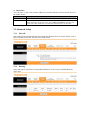
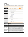
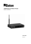
3.2.3
Wireless LAN Settings
Item
SSID
Broadcast
Description
The SSID is a unique name to identify the ADSL Router in the wireless LAN.
Wireless clients associating to the ADSL Router must have the same SSID.
Select No to hide the SSID such that a station can not obtain the SSID through
passive scanning. Select Yes to make the SSID visible so a station can obtain the
SSID
Channel ID
SSID through passive scanning.
The range of radio frequencies used by IEEE 802.11b/g wireless devices is
called a channel.
a. WEP
WEP (Wired Equivalent Privacy) encrypts data frames before transmitting over the wireless
network. Select Disable to allow all wireless computers to communicate with the access
points without any data encryption. Select 64-bit WEP or 128-bit WEP to use data
encryption.
Item
Key#1~Key#4
Description
The WEP keys are used to encrypt data. Both the ADSL Router and the wireless
clients must use the same WEP key for data transmission. If you chose 64-bit
WEP, then enter any 10 hexadecimal digits ("0-9", "A-F") preceded by 0x for
each key (1-4). If you chose 128-bit WEP, then enter 26 hexadecimal digits
("0-9", "AF") preceded by 0x for each key (1-4).The values must be set up
exactly the same on the Access Points as they are on the wireless client stations.
The same value must be assigned to Key 1 on both the access point (your ADSL
Router) and the client adapters, the same value must be assigned to Key 2 on
both the access point and the client stations and so on, for all four WEP keys.
b. WPA-PSK
Wi-Fi Protected Access, pre-shared key. Encrypts data frames before transmitting over the
wireless network.
Item
Pre-shared
Key
Description
The Pre-shared Key is used to encrypt data. Both the ADSL Router and the
wireless clients must use the same WPA-PSK key for data transmission.
c. Advanced setting
Item
Description
The Beacon Interval value indicates the frequency interval of the beacon. Enter a
Beacon
value between 20 and 1000. A beacon is a packet broadcast by the Router to
Interval
RTS Threshold
Fragment
Threshold
DTIM
synchronize the wireless network.
The RTS (Request To Send) threshold (number of bytes) for enabling RTS/CTS
handshake. Data with its frame size larger than this value will perform the
RTS/CTS handshake. Setting this attribute to be larger than the maximum
MSDU (MAC service data unit) size turns off the RTS/CTS handshake. Setting
this attribute to zero turns on the RTS/CTS handshake. Enter a value between 0
and 2432.
The threshold (number of bytes) for the fragmentation boundary for directed
messages. It is the maximum data fragment size that can be sent. Enter a value
between 256 and 2432.
This value, between 1 and 255, indicates the interval of the Delivery Traffic
Indication Message (DTIM).
d. MAC Filter
You can allow or deny a list of MAC addresses associated with the wireless stations access to
the ADSL Router.
Item
Description
Use the drop down list box to enable or disable MAC address filtering.
Status
Select Deny Association to block access to the router, MAC addresses not listed
Action
will be allowed to access the router. Select Allow Association to permit access
to the router, MAC addresses not listed will be denied access to the router.
3.3 Advanced Setup
3.3.1
Firewall
Select this option can automatically detect and block Denial of Service (DoS) attacks, such as
Ping of Death, SYN Flood, Port Scan and Land Attack.
3.3.2
Routing
Select this Option will list the routing table information. You can also Add/Edit/Drop the
static route.
a. Static Route
Select this option to set static Routing information.
Item
Destination IP
Address
IP Subnet
Mask
Gateway IP
Address
Metric
Announced in
RIP
3.3.3
Description
This parameter specifies the IP network address of the final destination.
Enter the subnet mask for this destination.
Enter the IP address of the gateway. The gateway is an immediate neighbor of
your ADSL Router that will forward the packet to the destination. On the LAN,
the gateway must be a router on the same segment as your Router; over Internet
(WAN), the gateway must be the IP address of one of the remote nodes.
Metric represents the "cost" of transmission for routing purposes. IP Routing
uses hop count as the measurement of cost, with a minimum of 1 for directly
connected networks. Enter a number that approximates the cost for this link. The
number need not to be precise, but it must between 1 and 15. In practice, 2 or 3
is usually a good number.
This parameter determines if the ADSL router will include the route to this
remote node in its RIP broadcasts. If set to Yes, the route to this remote node
will be propagated to other hosts through RIP broadcasts. If No, this route is kept
private and is not included in RIP broadcasts.
NAT
Select this option to setup the NAT (Network Address Translation) function for your ADSL
router.
Item
Virtual Circuit
NAT Status
Number of IPs
Description
Enter Virtual Circuit Index that you plan to setup for the NAT function
This field shows the current status of the NAT function for the current VC.
This field is to specify how many IPs are provided by your ISP for current VC. It
can be single IP or multiple IPs.
Note: for VCs with single IP, they share the same DMZ and Virtual servers; for
VCs with multiple IPs, each VC can set DMZ and Virtual servers. Furthermore,
for VCs with multiple IPs, they can define the Address Mapping rules; for VCs
with single IP, since they have only one IP, there is no need to individually
define the Address Mapping rule.
a. DMZ
A DMZ (demilitarized zone) is a host between a private local network and the outside public
network. It prevents outside users from getting direct access to a server that has company data.
Users of the public network outside the company can access only the DMZ host.
Item
DMZ Host IP
Address
Description
Enter the specified IP Address for DMZ host on the LAN side.
b. Virtual Server
The Virtual Server is the server or server(s) behind NAT (on the LAN), for example, Web
server or FTP server, that you can make visible to the outside world even though NAT makes
your whole inside network appear as a single machine to the outside world.
Item
Rule Index
Start & End
port number
Local IP
Address
Description
The Virtual server rule index for this VC. You can specify 10 rules in maximum.
All the VCs with single IP will use the same Virtual Server rules.
Enter the specific Start and End Port number you want to forward. If it is one
port only, you can enter the End port number the same as Start port number. For
example, you want to set the FTP Virtual server, you can set the start and end
port number to 21.
Enter the IP Address for the Virtual Server in LAN side.
c. IP Address Mapping
The IP Address Mapping is for those VCs that with multiple IPs. The IP Address Mapping
rule is per-VC based. (Only for Multiple IPs' VCs).
Item
Rule Index
Rule Type
Local Start &
End IP
Public Start &
End IP
Description
The Virtual server rule index for this VC. You can specify 10 rules in maximum.
All the VCs with single IP will use the same Virtual Server rules.
There are four types of one-to-one, Many-to-One, Many-to-Many Overload and
Many-to-Many No-overload.
Enter the local IP Address you plan to mapped to. Local Start IP is the starting
local IP address and Local End IP is the ending local IP address. If the rule is for
all local IPs, then the Start IP is 0.0.0.0 and the End IP is 255.255.255.255.
Enter the public IP Address you want to do NAT. Public Start IP is the starting
public IP address and Public End IP is the ending public IP address. If you have
a dynamic IP, enter 0.0.0.0 as the Public Start IP.
3.3.4
QoS
(Quality of Service)
This option will provide better service of selected network traffic over various technologies.
a. 802.1p
Select this option to Activate/Deactivated the 802.1p IEEE 802.1p establishes eight levels of
priority (0 ~ 7). Although network managers must determine actual mappings, IEEE has made
broad recommendations. Seven is the highest priority which is usually assigned to
network-critical traffic such as Routing Information Protocol (RIP) and Open Shortest Path
First (OSPF) table updates. Five and six are often for delay-sensitive applications such as
interactive video and voice. Data classes four through one range from controlled-load
applications such as streaming multimedia and business-critical traffic - carrying SAP data,
for instance - down to "loss eligible" traffic. Zero is used as a best-effort default priority,
invoked automatically when no other value has been set.
b. IP QoS
Select this option to Activated/Deactivated the IP QoS on different types (IP ToS and
DiffServ). IP QoS function is intended to deliver guaranteed as well as differentiated Internet
services by giving network resource and usage control to the Network operator.
c. Applications QoS
Select this option to Activated/Deactivated the different application packets prioritized on the
queues.
d. VLAN Group QoS
Select this option to Activated/Deactivated the 4094 VID on the 4 different queues. VID
(VLAN ID) is the identification of the VLAN, which is basically used by the standard 802.1Q.
It has 12 bits and allow the identification of 4096 (2^12) VLANs. Of the 4096 possible VIDs,
a VID of 0 is used to identify priority frames and value 4095 (FFF) is reserved, so the
maximum possible VLAN configurations are 4,094.
3.3.5
VLAN
Virtual LAN (VLAN) is a group of devices on one or more LANs that are configured so that
they can communicate as if they were attached to the same wire, when in fact they are located
on a number of different LAN segments. Because VLANs are based on logical instead of
physical connections, it is very flexible for user/host management, bandwidth allocation and
resource optimization.
1.Port-Based VLAN: each physical switch port is configured with an access list
specifying membership in a set of VLANs.
2.ATM VLAN - using LAN Emulation (LANE) protocol to map Ethernet packets into
ATM cells and deliver them to their destination by converting an Ethernet MAC address
into an ATM address.
The key for the IEEE 802.1Q to perform the above functions is in its tags. 802.1Q-compliant
switch ports can be configured to transmit tagged or untagged frames. A tag field containing
VLAN (and/or 802.1p priority) information can be inserted into an Ethernet frame. If a port
has an 802.1Q-compliant device attached (such as another switch), these tagged frames can
carry VLAN membership information between switches, thus letting a VLAN span multiple
switches. However, it is important to ensure ports with non-802.1Q-compliant devices
attached are configured to transmit untagged frames. Many NICs for PCs and printers are not
802.1Q-compliant. If they receive a tagged frame, they will not understand the VLAN tag and
will drop the frame. Also, the maximum legal Ethernet frame size for tagged frames was
increased in 802.1Q (and its companion, 802.3ac) from 1,518 to 1,522 bytes. This could cause
network interface cards and older switches to drop tagged frames as "oversized."
a. PVID ( Port VLAN ID)
Each physical port has a default VID called PVID (Port VID). PVID is assigned to untagged
frames or priority tagged frames (frames with null (0) VID) received on this port.
3.3.6
ADSL
The ADSL feature can be selected when you meet the physical connection problem. Please
check the proper settings with your Internet service provider.
a. ADSL Mode
Select the ADSL operation mode which your ADSL connection uses.
b. ADSL Type
Select the ADSL operation type which your ADSL connection uses.
3.4 Access Management
3.4.1
ACL
The user may remotely access the ADSL Router once setting his IP as a Secure IP Address
through selected applications. With the default IP 0.0.0.0, any client would be allowed to
remotely access the ADSL Router.
3.4.2
IP Filter
The user can set different IP filter rules of a given protocol (TCP, UDP or ICMP) and a
specific direction (incoming, outgoing, or both) to filter the packets.
3.4.3
SNMP
Simple Network Management Protocol is used for exchanging information between network
devices.
Item
Description
Get Community
Select to set the password for the incoming Get- and GetNext requests from the
management station.
Set Community
Select to set the password for incoming Set requests from the management
station.
3.4.4
UPnP
UPnP (Universal Plug and Play) is a distributed, open networking standard that uses TCP/IP
for simple peer-to-peer network connectivity between devices. A UPnP device can
dynamically join a network, obtain an IP address, convey its capabilities and learn about other
devices on the network. In turn, a device can leave a network smoothly and automatically
when it is no longer in use. UPnP broadcasts are only allowed on the LAN.
Item
Description
Auto-Configure UPnP network devices can automatically configure network addressing,
announce their presence in the network to other UPnP devices and enable
exchange of simple product and service descriptions.
3.4.5
DDNS
The Dynamic Domain Name System lets you use a static host name with a dynamic IP
address. User should type the host name, user name and password assigned to your ADSL
Router by your Dynamic DNS provider. User also can decide to turn on DYNDNS Wildcard
or not.
3.4.6
CWMP
It is description for CWMP.
3.5 Maintenance
3.5.1
Administration
There is only one account that can access Web-Management interface. The default account is
"admin", and the password is "admin". Admin has read/write access privilege. In this web
page, you can set new password for admin.
3.5.2
Time Zone
The system time is the time used by the device for scheduling services. You can manually set
the time or connect to a NTP (Network Time Protocol) server. If a NTP server is set, you will
only need to set the time zone. If you manually set the time, you may also set Daylight Saving
dates and the system time will automatically adjust on those dates.
3.5.3
Firmware
You can upgrade the firmware of the Router in this page. Make sure the firmware you want to
use is on the local hard drive of the computer. Click on Browse to browse the local hard drive
and locate the firmware to be used for upgrade.
3.5.4
SysRestart
User can restart the device with current settings or factory default settings.
3.5.5
Diagnostics
The Diagnostic Test page shows the test results for the connectivity of the physical layer and
protocol layer for both LAN and WAN sides.
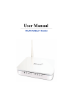
3.6 Status
3.6.1
Device Info
This page displays the current information for the ADSL Router. It will display the Firmware
version, LAN, WAN, and MAC address information.
Item
Description
Line State
This field displays the ADSL connection process and status.
Modulation
This field displays the ADSL modulation status for G.dmt or T1.413.
Annex Mode
This field displays the ADSL annex modes for Annex A or Annex B.
Max Tx Power
This field displays the transmit output power level of the ADSL Router.
SNR Margin
Amount of increased noise that can be tolerated while maintaining the designed
BER (bit error rate). The SNR Margin is set by Central Office DSLAM. If the
SNR Margin is increased, bit error rate performance will improve, but the data
rate will decrease. Conversely, if the SNR Margin is decreased, bit error rate
performance will decrease, but the data rate will increase.
Line
Attenuation
Attenuation is the decrease in magnitude of the ADSL line signal between the
transmitter (Central Office DSLAM) and the receiver (Client ADSL Modem),
measured in dB. It is measured by calculating the difference in dB between the
signal power level received at the Client ADSL Router and the reference signal
power level transmitted from the Central Office DSLAM.
Data Rate
This field displays the ADSL data rate.
3.6.2
System Log
The ADSL Router keeps a running log of events and activities occurring on the Router. If the
device is rebooted, the logs are automatically cleared.
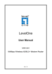
3.6.3
Statistics
The ADSL Router keeps statistic of traffic that passes through it. You are able to view the
amount of packets that pass through the Router on both the WAN port and the LAN port. The
traffic counter will reset if the device is rebooted. You can select Ethernet/ADSL to view the
statistics report of LAN/WAN.