1
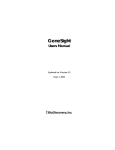
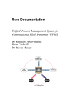
Pipeline Current Mapper User Guide
Section 1
PCM Transmitter Functions
The PCM transmitter is housed in a rugged
waterproof case which can be opened easily by
applying a slight pressure to the top of the case just
above the clips. The clips will then open freely.
In certain situations the air pressure within the
case may need to be equalised by unscrewing
the small knob located by the handle.
The case needs to remain open during
operation to allow the heat sink to cool.
When closing case ensure connection cables
are kept away from the heat sink and the
support strut.
PCM-Tx
Serial No.
Output OK
1 .00
Temerature
Over Temperature
Power Limit
Output Current (A)
The three-position rotary switch selects the applied
mapping frequencies as follows:
Voltage Limit
Output Voltage Level
1A
600 mA
ELF
ELF
LF
2A
300 mA
Frequency Select
The 4 Hz output current is shown on the LCD.
100 mA
3A
Output Level
TRANSMISSION LINES
ELF maximum range.
• 35% 4 Hz
• 65% ELF (128 Hz or 98 Hz)
TRANSMISSION AND DISTRIBUTION LINES
ELF current direction, medium range.
• 35% 4 Hz
• 30% 8 Hz (current direction)
• 35% ELF (128 Hz or 98 Hz)
Frequency Select
DISTRIBUTION LINES
LF current direction, alternative frequency.
• 35% 4 Hz
• 30% 8 Hz (current direction)
• 35% LF (640 Hz or 512 Hz)
PCM-Tx
Serial No.
Output OK
1 .00
Over Temerature
Power Limit
Output Current (A)
Voltage Limit
Output Voltage Level
600 mA
1A
ELF
ELF
2A
300 mA
100 mA
3A
Output Level
Page 4
The 4 Hz mapping frequency is always present.
The operator has a choice of selecting the locate
frequency and current direction indication if
required for identification in congested areas or for
fault finding.
LF
Current Select
The six position Current Select rotary switch
selects the following rms 4 Hz current settings: 100
mA, 300 mA, 600 mA, 1 A, 2 A, 3 A.
When the PCM Transmitter is in operation, the
selected current will remain at a constant level,
unless input power supply limit is reached.
Frequency Select