1
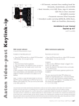
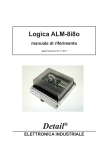
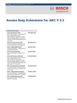
RS485 MODBUS Module 8I8O
Expansion Module – 8 digital inputs, 8 digital outputs
Version 2.2 — 12/01/2014
User Manual
Manufactured for
RS485 MODBUS Module 8I8O
SfAR
User Manual
Thank you for choosing our product.
This manual will help you with proper support and proper operation of the device.
The information contained in this manual have been prepared with utmost care by our
professionals and serve as a description of the product without incurring any liability for
the purposes of commercial law.
This information does not release you from the obligation of own judgment and
verification.
We reserve the right to change product specifications without notice.
Please read the instructions carefully and follow the recommendations contained
therein.
WARNING!
Failure to follow instructions can result in equipment damage or impede
the use of the hardware or software.
Expansion Module– 8 digital inputs, 8 digital outputs
User Manual
© SfAR 2011-2014. All rights reserved.
Version 2.2 - 12/01/2014
2 / 17
RS485 MODBUS Module 8I8O
SfAR
User Manual
1. Safety rules
•
Before first use, refer to this manual
•
Before first use, make sure that all cables are connected properly
•
Please ensure proper working conditions, according to the device specifications
(eg: supply voltage, temperature, maximum power consumption)
•
Before making any modifications to wiring connections, turn off the power supply
2. Module Features
2.1. Purpose and description of the module
8I8O Module is an innovative device that provides a simple and cost-effective
extension of the number of lines of input and output in popular PLCs.
The module has 8 digital inputs with configurable timer/counter option and 8
digital outputs. In addition, terminals IN1 and IN2 and IN3 and IN4 can be used to
connect two encoders. All inputs and outputs are isolated from the logic of using
optocouplers. Each channel can be individually configured in one of several modes.
This module is connected to the RS485 bus with twisted-pair wire.
Communication is via MODBUS RTU or MODBUS ASCII. The use of 32-bit ARM
core processor provides fast processing and quick communication. The baud rate is
configurable from 2400 to 115200.
The module is designed for mounting on a DIN rail in accordance with
DIN EN 5002.
The module is equipped with a set of LEDs used to indicate the status of inputs
and outputs useful for diagnostic purposes and helping to find errors.
Module configuration is done via USB by using a dedicated computer program.
You can also change the parameters using the MODBUS protocol.
Expansion Module– 8 digital inputs, 8 digital outputs
User Manual
© SfAR 2011-2014. All rights reserved.
Version 2.2 - 12/01/2014
3 / 17
RS485 MODBUS Module 8I8O
SfAR
User Manual
2.2. Technical Specifications
Power Supply
Digital Inputs
Digital Outputs
Counters
Temperature
Connectors
Size
Interface
*
Voltage
12-24 V DC ± 20%
Maximum Current
200 mA @ 12V / 100 mA @ 24V
No of inputs
8
Voltage range
0 – 36V
Low State „0”
0 – 3V
High State „1”
6 – 36V
Input impedance
4kΩ
Isolation
1500 Vrms
Input Type
PNP or NPN
No of outputs
8
Max Voltage
30V
Max current
500mA
Output Type
PNP
Output protection
4A polymer fuse
No
8
Resolution
32 bits
Frequency
1kHz (max)
Impulse Width
500 μs (min)
Work
-10 °C - +50°C
Storage
-40 °C - +85°C
Power Supply
2 pin
Communication
3 pin
Inputs
10 pin
Outputs
10 pin
Quick connector
IDC10
Configuration
Mini USB
Height
120 mm
Length
101 mm
Width
22,5 mm
RS485
Up to 128 devices
*
Maximum current with active Modbus transmission, all outputs on and high state on all inputs
Expansion Module– 8 digital inputs, 8 digital outputs
User Manual
© SfAR 2011-2014. All rights reserved.
Version 2.2 - 12/01/2014
4 / 17
SfAR
RS485 MODBUS Module 8I8O
User Manual
2.3. Dimensions of the product
Look and dimensions of the module are shown below. The module is mounted
directly to the rail in the DIN industry standard. Power connectors, communication and
IOs are at the bottom and top of the module. USB connector configuration and
indicators located on the front of the module.
Expansion Module– 8 digital inputs, 8 digital outputs
User Manual
© SfAR 2011-2014. All rights reserved.
Version 2.2 - 12/01/2014
5 / 17
RS485 MODBUS Module 8I8O
SfAR
User Manual
3. Communication configuration
3.1. Grounding and shielding
In most cases, IO modules will be installed in an enclosure along with other
devices which generate electromagnetic radiation. Examples of these devices are relays
and contactors, transformers, motor controllers etc. This electromagnetic radiation can
induce electrical noise into both power and signal lines, as well as direct radiation into
the module causing negative effects on the system. Appropriate grounding, shielding
and other protective steps should be taken at the installation stage to prevent these
effects. These protective steps include control cabinet grounding, module grounding,
cable shield grounding, protective elements for electromagnetic switching devices,
correct wiring as well as consideration of cable types and their cross sections.
3.2. Network Termination
Transmission line effects often present a problem on data communication
networks. These problems include reflections and signal attenuation.
To eliminate the presence of reflections from the end of the cable, the cable must
be terminated at both ends with a resistor across the line equal to its characteristic
impedance. Both ends must be terminated since the direction of propagation is bidirectional. In the case of an RS485 twisted pair cable this termination is typically
120 Ω.
3.3. Setting Module Address in RS485 Modbus Network
The following table shows how to set switch to determine the address of the
module. The module address is set with the switches in the range of 0 to 31. Addresses
From 32 to 255 can by set via RS485 or USB.
Adr SW5 SW4 SW3 SW2 SW1
Adr SW5 SW4 SW3 SW2 SW1
Adr SW5 SW4 SW3 SW2 SW1
0
OFF OFF OFF OFF OFF
11
OFF
ON
OFF
ON
ON
22
ON
OFF
ON
ON
OFF
1
OFF OFF OFF OFF
ON
12
OFF
ON
ON
OFF OFF
23
ON
OFF
ON
ON
ON
2
OFF OFF OFF
ON
OFF
13
OFF
ON
ON
OFF
ON
24
ON
ON
OFF OFF OFF
3
OFF OFF OFF
ON
ON
14
OFF
ON
ON
ON
OFF
25
ON
ON
OFF OFF
ON
4
OFF OFF
ON
OFF OFF
15
OFF
ON
ON
ON
ON
26
ON
ON
OFF
ON
OFF
5
OFF OFF
ON
OFF
ON
16
ON
OFF OFF OFF OFF
27
ON
ON
OFF
ON
ON
6
OFF OFF
ON
ON
OFF
17
ON
OFF OFF OFF
ON
28
ON
ON
ON
OFF OFF
7
OFF OFF
ON
ON
ON
18
ON
OFF OFF
ON
OFF
29
ON
ON
ON
OFF
ON
8
OFF
ON
OFF OFF OFF
19
ON
OFF OFF
ON
ON
30
ON
ON
ON
ON
OFF
9
OFF
ON
OFF OFF
ON
20
ON
OFF
ON
OFF OFF
31
ON
ON
ON
ON
ON
10
OFF
ON
OFF
OFF
21
ON
OFF
ON
OFF
ON
Expansion Module– 8 digital inputs, 8 digital outputs
User Manual
ON
© SfAR 2011-2014. All rights reserved.
Version 2.2 - 12/01/2014
6 / 17
RS485 MODBUS Module 8I8O
SfAR
User Manual
3.4. Types of Modbus Registers
There are 4 types of variables available in the module
Type
Beginning
address
1
00001
Digital Outputs
Bit
1, 5, 15
Read & Write
2
10001
Digital Inputs
Bit
Read
2
3
30001
Input Registers
Registered
Read
3
4
40001
Output Registers
Registered
4, 6, 16
Read & Write
Variable
Modbus
Command
Access
3.5. Communication settings
The data stored in the modules memory are in 16-bit registers. Access to
registers is via MODBUS RTU or MODBUS ASCII.
3.5.1. Default settings
You can restore the default configuration by the switch SW6 (see 3.5.2 - Restore
the default configuration)
Baud rate
19200
Parity
No
Data bits
8
Stop bits
1
Reply Delay [ms]
0
Modbus Type
RTU
3.5.2. Restore the default configuration
To restore the default configuration:
•
turn off the power
•
turn on the switch SW6
•
turn on the power
•
when power and communication LED flash turn off the switch SW6
Caution! After restoring the default configuration all values stored in the registers will
be cleared as well.
Expansion Module– 8 digital inputs, 8 digital outputs
User Manual
© SfAR 2011-2014. All rights reserved.
Version 2.2 - 12/01/2014
7 / 17
RS485 MODBUS Module 8I8O
SfAR
User Manual
3.5.3. Configuration registers
Modbus
Dec
Hex
Address
40003
2
0x02
Name
Baud rate
0 – 2400
1 – 4800
2 – 9600
3 – 19200
4 – 38400
5 – 57600
6 – 115200
other – value * 10
0 – none
1 – odd
2 – even
3 – always 1
4 – always 0
40005
4
0x04
Parity
40004
3
0x03
Stop Bits LSB
1 – one stop bit
2 – two stop bits
40004
3
0x03
Data Bits MSB
7 – 7 data bits
8 – 8 data bits
40006
5
0x05
Response delay
40007
6
0x06
Modbus Mode
Expansion Module– 8 digital inputs, 8 digital outputs
User Manual
Values
Time in ms
0 – RTU
1 – ASCII
© SfAR 2011-2014. All rights reserved.
Version 2.2 - 12/01/2014
8 / 17
RS485 MODBUS Module 8I8O
SfAR
User Manual
4. Indicators
Outputs state 1 – 8
Power Supply
Communication
Inputs State 1 – 8
Indicator
Power supply
Description
LED indicates that the module is correctly powered.
Communication The LED lights up when the unit received the correct packet and sends the answer.
Inputs state
Outputs state
LED indicates that on the input is high state.
LED indicates that the output is on.
Expansion Module– 8 digital inputs, 8 digital outputs
User Manual
© SfAR 2011-2014. All rights reserved.
Version 2.2 - 12/01/2014
9 / 17
RS485 MODBUS Module 8I8O
SfAR
User Manual
5. Module Connection
SUPPLY
MAX 30V
V+
Output 1
Output 2
Output 3
Output 4
Output 5
Output 7
Output 6
V+
Output 8
V-
MAX
50 VDC
Supply
12/24 VDC
± 20%
COM
COM
Input 8
Input 7
Input 6
Input 5
Input 4
Input 3
Input 2
Input 1
IN 1
IN 2
IN 3
IN 4
IN 5
IN 6
IN 7
IN 8
COM
COM
VCC
GND
GND
RS485 -
RS485 +
INPUTS IMPEDANCE 4kΩ
LOW: 0 - 3 V
HIGH: 6 - 36V
SfAR
MAX 0.5A
D+
D-
SHIELD
V-
Quick
connector
RS-485
RS485 MODBUS Module 8I8O
VV+
OUT 8
OUT 7
OUT 6
OUT 5
OUT 4
OUT 3
OUT 2
OUT 1
V-
The ability to connect
up to two encoders
IN1 - A1
IN2 - B1
IN3 - A2
IN4 - B2
V+
POWER
SUPPLY
10-30V
Expansion Module– 8 digital inputs, 8 digital outputs
User Manual
© SfAR 2011-2014. All rights reserved.
Version 2.2 - 12/01/2014
10 / 17
RS485 MODBUS Module 8I8O
SfAR
User Manual
6. Switches
Switch
Function
1
Module address +1
2
Module address +2
3
Module address +4
4
Module address +8
5
Module address +16
6
Restoring default settings
Description
Setting module address from 0 to 31
Restoring default settings
(see 3.5.1 - Default settings and 3.5.2 - Restore the
default configuration).
Expansion Module– 8 digital inputs, 8 digital outputs
User Manual
© SfAR 2011-2014. All rights reserved.
Version 2.2 - 12/01/2014
11 / 17
RS485 MODBUS Module 8I8O
SfAR
User Manual
7. Modules Registers
7.1. Registered access
Modbus Dec Hex
Register Name
Access
Description
30001
0
0x00 Version/Type
Read
Version and Type of the device
30002
1
0x01 Switches
Read
Switches state
40003
2
0x02 Baud rate
Read & Write
RS485 baud rate
40004
3
0x03 Stop Bits & Data Bits
Read & Write
No of Stop bits & Data Bits (see 3.5.3)
40005
4
0x04 Parity
Read & Write
Parity bit
40006
5
0x05 Response Delay
Read & Write
Response delay in ms
40007
6
0x06 Modbus Mode
Read & Write
Modbus Mode (ASCII or RTU)
40009
8
0x08 Watchdog
Read & Write
Watchdog
40013
12 0x0C Default Output State
Read & Write
Default output state (after power on or
watchdog reset)
40033
32
0x20 Received packets MSB Read & Write
40034
33
0x21 Received packets LSB
Read & Write
40035
34
0x22 Incorrect packets MSB
Read & Write
40036
35
0x23 Incorrect packets LSB
Read & Write
40037
36
0x24 Sent packets MSB
Read & Write
40038
37
0x25 Sent packets LSB
Read & Write
30051
50
0x32 Inputs
Read
Inputs state
40052
51
0x33 Outputs
Read & Write
Output state
40053
52
0x34 Counter 1 MSB
Read & Write
40054
53
0x35 Counter 1 LSB
Read & Write
40055
54
0x36 Counter 2 MSB
Read & Write
40056
55
0x37 Counter 2 LSB
Read & Write
40057
56
0x38 Counter 3 MSB
Read & Write
40058
57
0x39 Counter 3 LSB
Read & Write
40059
58
0x3A Counter 4 MSB
Read & Write
40060
59
0x3B Counter 4 LSB
Read & Write
40061
60 0x3C Counter 5 MSB
Read & Write
40062
61 0x3D Counter 5 LSB
Read & Write
40063
62
0x3E Counter 6 MSB
Read & Write
40064
63
0x3F Counter 6 LSB
Read & Write
40065
64
0x40 Counter 7 MSB
Read & Write
40066
65
0x41 Counter 7 LSB
Read & Write
40067
66
0x42 Counter 8 MSB
Read & Write
Expansion Module– 8 digital inputs, 8 digital outputs
User Manual
No of received packets
No of received packets with error
No of sent packets
32-bit counter 1
32-bit counter 2
32-bit counter 3
32-bit counter 4
32-bit counter 5
32-bit counter 6
32-bit counter 7
32-bit counter 8
© SfAR 2011-2014. All rights reserved.
Version 2.2 - 12/01/2014
12 / 17
RS485 MODBUS Module 8I8O
SfAR
User Manual
Modbus Dec Hex
Register Name
Access
Description
40068
67
0x43 Counter 8 LSB
Read & Write
40085
84
0x54 CCounter 1 MSB
Read & Write
40086
85
0x55 CCounter 1 LSB
Read & Write
40087
86
0x56 CCounter 2 MSB
Read & Write
40088
87
0x57 CCounter 2 LSB
Read & Write
40089
88
0x58 CCounter 3 MSB
Read & Write
40090
89
0x59 CCounter 3 LSB
Read & Write
40091
90
0x5A CCounter 4 MSB
Read & Write
40092
91
0x5B CCounter 4 LSB
Read & Write
40093
92 0x5C CCounter 5 MSB
Read & Write
40094
93 0x5D CCounter 5 LSB
Read & Write
40095
94
0x5E CCounter 6 MSB
Read & Write
40096
95
0x5F CCounter 6 LSB
Read & Write
40097
96
0x60 CCounter 7 MSB
Read & Write
40098
97
0x61 CCounter 7 LSB
Read & Write
40099
98
0x62 CCounter 8 MSB
Read & Write
40100
99
0x63 CCounter 8 LSB
Read & Write
40117
116 0x74 Counter Config 1
Read & Write
40118
117 0x75 Counter Config 2
Read & Write
40119
118 0x76 Counter Config 3
Read & Write
40120
119 0x77 Counter Config 4
Read & Write
40121
120 0x78 Counter Config 5
Read & Write
40122
121 0x79 Counter Config 6
Read & Write
40123
122 0x7A Counter Config 7
Read & Write
40124
123 0x7B Counter Config 8
Read & Write
40133
132 0x84 Catch
Read & Write
Catch counter
40134
133 0x85 Status
Read & Write
Captured counter
Expansion Module– 8 digital inputs, 8 digital outputs
User Manual
32-bit value of captured counter 1
32-bit value of captured counter 2
32-bit value of captured counter 3
32-bit value of captured counter 4
32-bit value of captured counter 5
32-bit value of captured counter 6
32-bit value of captured counter 7
32-bit value of captured counter 8
Counter Configuration
+1 – time measurement (if 0 counting
impulses)
+2 – autocatch counter every 1 sec
+4 – catch value when input low
+8 – reset counter after catch
+16 – reset counter if input low
+32 – encoder (only for counter 1 and 3)
© SfAR 2011-2014. All rights reserved.
Version 2.2 - 12/01/2014
13 / 17
RS485 MODBUS Module 8I8O
SfAR
User Manual
7.2. Bit access
Modbus
Dec
Hex
Address Address Address
Register name
Access
Description
193
192
0x0C0 Default state of output 1 Read & Write
Default state of output 1
194
193
0x0C1 Default state of output 2 Read & Write
Default state of output 2
195
194
0x0C2 Default state of output 3 Read & Write
Default state of output 3
196
195
0x0C3 Default state of output 4 Read & Write
Default state of output 4
197
196
0x0C4 Default state of output 5 Read & Write
Default state of output 5
198
197
0x0C5 Default state of output 6 Read & Write
Default state of output 6
199
198
0x0C6 Default state of output 7 Read & Write
Default state of output 7
200
199
0x0C7 Default state of output 8 Read & Write
Default state of output 8
10801
800
0x320 Input 1
Read
Input 1 state
10802
801
0x321 Input 2
Read
Input 2 state
10803
802
0x322 Input 3
Read
Input 3 state
10804
803
0x323 Input 4
Read
Input 4 state
10805
804
0x324 Input 5
Read
Input 5 state
10806
805
0x325 Input 6
Read
Input 6 state
10807
806
0x326 Input 7
Read
Input 7 state
10808
807
0x327 Input 8
Read
Input 8 state
817
816
0x330 Output 1
Read & Write
Output 1 state
818
817
0x331 Output 2
Read & Write
Output 2 state
819
818
0x332 Output 3
Read & Write
Output 3 state
820
819
0x333 Output 4
Read & Write
Output 4 state
821
820
0x334 Output 5
Read & Write
Output 5 state
822
821
0x335 Output 6
Read & Write
Output 6 state
823
822
0x336 Output 7
Read & Write
Output 7 state
824
823
0x337 Output 8
Read & Write
Output 8 state
2113
2112
0x840 Capture 1
Read & Write
Capture counter 1
2114
2113
0x841 Capture 2
Read & Write
Capture counter 2
2115
2114
0x842 Capture 3
Read & Write
Capture counter 3
2116
2115
0x843 Capture 4
Read & Write
Capture counter 4
2117
2116
0x844 Capture 5
Read & Write
Capture counter 5
2118
2117
0x845 Capture 6
Read & Write
Capture counter 6
2119
2118
0x846 Capture 7
Read & Write
Capture counter 7
2120
2119
0x847 Capture 8
Read & Write
Capture counter 8
2129
2120
0x848 Captured 1
Read & Write
Captured value of counter 1
Expansion Module– 8 digital inputs, 8 digital outputs
User Manual
© SfAR 2011-2014. All rights reserved.
Version 2.2 - 12/01/2014
14 / 17
RS485 MODBUS Module 8I8O
SfAR
User Manual
Modbus
Dec
Hex
Address Address Address
Register name
Access
Description
2130
2129
0x849 Captured 2
Read & Write
Captured value of counter 2
2131
2130
0x84A Captured 3
Read & Write
Captured value of counter 3
2132
2131
0x84B Captured 4
Read & Write
Captured value of counter 4
2133
2132
0x84C Captured 5
Read & Write
Captured value of counter 5
2134
2133
0x84D Captured 6
Read & Write
Captured value of counter 6
2135
2134
0x84E Captured 7
Read & Write
Captured value of counter 7
2136
2135
0x84F Captured 8
Read & Write
Captured value of counter 8
Expansion Module– 8 digital inputs, 8 digital outputs
User Manual
© SfAR 2011-2014. All rights reserved.
Version 2.2 - 12/01/2014
15 / 17
SfAR
RS485 MODBUS Module 8I8O
User Manual
8. Configuration software
Modbus Configurator is software that is designed to set the module registers
responsible for communication over Modbus network as well as to read and write the
current value of other registers of the module. This program can be a convenient way to
test the system as well as to observe real-time changes in the registers.
Communication with the module is done via the USB cable. The module does
not require any drivers.
Configurator is a universal program, whereby it is possible to configure all available
modules.
Expansion Module– 8 digital inputs, 8 digital outputs
User Manual
© SfAR 2011-2014. All rights reserved.
Version 2.2 - 12/01/2014
16 / 17
SfAR
RS485 MODBUS Module 8I8O
User Manual
Table of content
1. Safety rules.......................................................................................................................................3
2. Module Features...............................................................................................................................3
2.1. Purpose and description of the module.....................................................................................3
2.2. Technical Specifications...........................................................................................................4
2.3. Dimensions of the product........................................................................................................5
3. Communication configuration..........................................................................................................6
3.1. Grounding and shielding...........................................................................................................6
3.2. Network Termination................................................................................................................6
3.3. Setting Module Address in RS485 Modbus Network...............................................................6
3.4. Types of Modbus Registers.......................................................................................................7
3.5. Communication settings...........................................................................................................7
3.5.1. Default settings.................................................................................................................7
3.5.2. Restore the default configuration......................................................................................7
3.5.3. Configuration registers......................................................................................................8
4. Indicators..........................................................................................................................................9
5. Module Connection........................................................................................................................10
6. Switches..........................................................................................................................................11
7. Modules Registers..........................................................................................................................12
7.1. Registered access....................................................................................................................12
7.2. Bit access................................................................................................................................14
8. Configuration software...................................................................................................................16
Expansion Module– 8 digital inputs, 8 digital outputs
User Manual
© SfAR 2011-2014. All rights reserved.
Version 2.2 - 12/01/2014
17 / 17
Manufactured for:
Aspar s.c.
ul. Kapitańska 9
81-331 Gdynia
Poland
[email protected]
www.ampero.eu
Tel. +48 58 351 39 89; +48 58 732 71 73