1
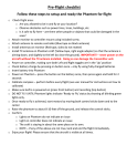
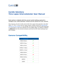
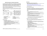
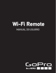
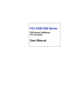
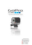
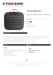
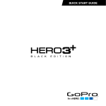
CamDo Solutions Motion Detector GoPro Controller MD-003. Revised February, 2015 This is the operating manual for the newer, MD-003 version of the controller board sold after March 17, 2013. If you have an earlier version of the product, please refer to the appropriate manual. Compatibility Camera Compatibility ( Y / N ) HERO4 Black ✔* HERO4 Silver ✔* HERO (2014) ✘ HERO3+ Black ✔ HERO3+ Silver ✔ HERO3 Black ✔ HERO3 Silver ✘ HERO3 White ✔ HERO2 ✔ HERO ✔ * NOTE: HERO4 compatibility can only be achieved through a custom >irmware modi>ication to the camera. The >irmware modi>ication is explained in detail here. The Motion Controller is used to take videos or still photographs when motion is detected by the passive infra-red (PIR) detector or the X-Band doppler radar detector. The controller is the same one used for time lapse photography, but the starting and stopping of the camera is based on the motion detector instead of the elapsed time. Both functions are available on the board you have received. Operation depends on the setting of the switches on the back of the board. The Motion Controller is compatible with the HD HERO, HERO2, HERO3 Black and White, HERO3+, and HERO4 cameras from GoPro. Before using the controller it is necessary to set the camera type as the operation of the HERO3 Black (or HERO3+/HERO4) cameras are different from previous models. Setting the Camera Type The HERO3 Black, HERO3+, and HERO4 cameras operate differently from the previous versions of GoPro cameras and requires a change in the way the controller operates. If the controller is set to operate a HERO3 Black, HERO3+, or HERO4 camera, it will turn on the HERO2 or other cameras, but won't turn it off. By default, the controller is configured for the HERO3 Black (or HERO3+/HERO4). To change camera types, set the dipswitches to 0011 and plug the controller board into the back of the camera. The green LED on the controller will flash twice to indicate that it is now configured to operate a HERO2 camera. Unplug the controller and reset the dipswitches to the desired operating mode. To change the configuration to HERO3 Black (or HERO3+/HERO4), set the switches to 0011 and plug the controller into the back of the camera. The LED will flash 3 times to indicate it is now configured to operate the HERO3 Black, HERO3+, and HERO4 cameras. Each time the controller is plugged in with the dipswitches set to 0011 the configuration will toggle between HERO2 and HERO3 modes of operation. Note that the HERO3 White camera works like a HERO2 camera. Select mode 2 for the HERO3 White Edition. All references to HERO2 in this document also refer to the HERO3 White Edition camera. Likewise, all references to HERO3 Black in this document also refer to HERO3+ and HERO4 cameras. Telling the camera what to do The controller turns the camera on. What the camera does is determined by the camera settings and, in the case of the HERO3 Black, by the script placed on the SD card. Before proceeding to set up the controller card, set up the camera and test it by pressing the MODE/POWER button to turn the camera on. Observe that it is doing what you expect it to do. HERO3 White and HERO2 cameras will remain on because the CamDo controller board will turn them off. HERO3 Black cameras will be turned off by the script, if that is what you have set them up to do. Setting GoPro One Button Mode The CamDo controller can only turn the camera on and off. It has no control over the shutter. To use the controller, the GoPro camera must be set to operate in One Button Mode. In One Button Mode, turning the camera on causes the camera to immediately begin taking photos or recording video without pressing the shutter. HD HERO. To use One Button Mode on the HD HERO, scroll through the settings and change OnF (the default) to OnO. Next, choose the default operating mode at power up, choose F for video (film), P for single shot, 3 for triple shot, or PES for sequential shots every few seconds. Skip several settings and choose from P1, P2, P5, P30 or P60 for one photo every 1,2,5,30 or 60 seconds while the camera is on. HERO2. To use One Button Mode on the GoPro HERO2, scroll through the settings and change One Button Mode to On and press the shutter button to confirm. Next, choose the default operating mode at power up, choose Video for video, Photo for single shot, Burst for triple shot, or Time Lapse for sequential shots every few seconds. Skip several settings and choose from the Time Lapse Modes for 0.5, 1,2,5,30 or 60 seconds while the camera is on. HERO3 White. To use One Button Mode on the GoPro HERO3 White, the WiFi must be disabled. Until GoPro releases a firmware updated, WiFi and One Button Mode cannot be used at the same time. The menu settings are the same as the HERO2, above. HERO3 Black/HERO3+. One Button Mode should be turned off and the camera is operated by the Super One Button Mode scripts which control the camera actions and the time the camera is turned off. The script can turn WiFi on, if needed. HERO4. One Button Mode should be turned off and the camera is operated by theCSI HERO4 Scripts which control the camera actions and the time the camera is turned off. The script can turn WiFi on, if needed. There are numerous videos on YouTube showing how to set up and use One Button Mode for each camera. Motion Detector Operation 0110. Set the switches on the back of the controller card to off-on-onoff 0110 to operate the controller as a motion detector which turns the camera on when there is motion. Turn off the camera. Plug the board into back of the camera. The camera will probably come on for a few seconds as the motion detector initiates. The PIR detector takes up to 5 minutes to adjust itself to the "no motion" state. During that time, it may fire off randomly. Ideally, no motion should occur in front of the detector during this learning period. The X-Band detector settles in a few seconds. Once settled, the detector will start the camera when motion is detected. The range depends on the conditions and the type of motion that occurs. Generally, people moving within 25 feet of the detector will set it off. The camera will begin recording when it first sees motion and continue to record for the programmed shoot time after the last motion occurs. Refer to the Time Lapse Intervalometer Operating Manual to adjust the shoot time. The default is 5 seconds. The HERO3 Black will remain on for the length of time defined in the Super One Button Mode script. If the camera turns off while there is still motion being detected, it will turn back on again and repeat the script. Care in siting the motion detector can help alleviate false positive triggers. The PIR motion detector responds to movement of warmth across its field of view. Sudden changes in sun and shade in front of the detector, such as the sun falling through leaves which are moving in the wind can create an effect which triggers the detector. Indoors, watch out for fans blowing warm or cold air across the detector's viewing angle. The green LED on the controller will be solid when the detector is detecting motion and for a few seconds afterwards. The sensor hold delay is set by the orange adjustment resistor on the PIR device. If your PIR has 2 adjustments, the left one determines the sensitivity of the detector (range) and the right one determines the hold time after sensing motion. Any programmed controller delay is added to the sensor hold time and is indicated by the flashing LED counting the seconds. The green LED will blink once per second as the controller counts down the shooting interval from last motion to camera turn-off. Motion Detection with Delayed Sense 0001. Motion Detection with fewer false triggers. This setting is the same as the 0110 setting above, but requires that the motion detector fire multiple times within 30 seconds before triggering the camera. This reduces the number of false triggers caused by the movement of branches, small birds, etc. It is designed to be useful for the detection of larger animals and people. It will probably be necessary to experiment to determine which setting is more appropriate for your application. The PIR detector sensor hold delay adjustment needs to be set to near minimum to make this setting useful. Otherwise, the detector's stretched output will be interpreted as an extended period of motion. Time Lapse Triggered by Motion 1110. Time lapse operation will be triggered by motion or external input. If the dipswitches are set to 1110, the controller will operate in time lapse mode only if there is an input sensed from the motion detector. The time lapse shoot time and cycle time can be programmed by the user. The default is a 5 second shot once every minute. Mixed Time Lapse with Motion Detection 1100. The mixed mode combines time lapse photography with motion detection. For example, if you wish to take a photograph once an hour regardless of whether there is any motion in front of the camera and you also want photographs when there is motion detected, this mode will do that. You can set the frequency of the photographs when motion is detected using the camera settings (up to 60 seconds between shots). The time lapse shots when there is no motion will be taken according the schedule programmed into the board following the instructions in the Time Lapse Intervalometer Operating Manual. Motion Detector Testing 0010 If the switches are set to off-off-on-off, the controller will enter a test mode. The green LED on the controller card will come on when motion is detected. This is handy for checking if you suspect a problem with the motion detector or the wiring, or for experimenting with the detector without triggering the camera. The HD HERO must be ON to use this test. With the HERO2 or 3 it doesn't matter if the camera is on or off. Motion Detector Connections The Rev 4 board does not require a separate battery or power source. Power is provided to the motion detector using the on-board power supply. The PIR detector is very efficient and battery life with no motion detected should be several weeks. The X-Band detector is an active device and will reduce battery life to about 3 days (HERO2) without an external power source. See below for how to add external power via the board or use the camera USB charging input to keep the battery charged. Connections between the Rev 4 Controller and the Motion Detectors Troubleshooting If there appears to be a problem, check the following: • • • • • • Make sure the switches are set to 0110 for motion detection. Check the SD card in the camera -‐ if there is no card, or the card is full, the camera will not respond in the normal way to turn on and turn off signals. Check the camera battery. If the battery is low, the camera can behave erratically. Check that the controller card is Cirmly seated in the socket on the camera. Check that the connectors in the cable are connected. Make sure the camera Cirmware is up to date. Triggering with Other Devices The motion detector control board can be triggered using other motion detectors, intervalometers,accelerometers, timers, computers, temperature sensors, radio or infra-red remote controls, and custom electronic circuits. The trigger input is an LTV-817 optoisolator with a 1K current limiting resistor. A signal from 3 volts to 20 volts between IN- and IN+ will trigger the controller to start the camera. The on time interval begins when the signal stops. Essentially, any device which will light an LED can trigger the controller. More technical information on using the controller with other devices is contained in the Application Notes for Advanced Users. Switching lights or other devices when the camera is on The controller board can turn on lights or trigger other devices when the camera is on during time lapse, or when triggered by the motion detector. Instructions for connecting external devices to the output of the controller are discussed in the Application Notes for Advanced Users. To save power, this function is not normally enabled. The 1011 switch setting will enable the function when you plug the board into a camera which is already turned on. The setting will be remembered until you disable it using the reset. To reset all settings to the factory defaults, set the switches to 1010, turn on the camera, then plug the board into the camera. Timer Controller The timer controller is used to take time lapse photographs and control the times the camera is off and on. No batteries are required. The negligible amount of power required is provided by the camera battery. All of the features of the Time Lapse Intervalometer product are available on the Motion Detector board. Unplug the motion detector from the board if you are only using the Time Lapse features. This will maximize battery life. Time Lapse Operation 1111. When you receive the controller it will be pre-programmed for one photo every 60 seconds. 4. 1.Use the menus to set up One Button Mode P2 (Time Lapse 2 seconds) on the camera. 2.Turn the camera OFF. 3.Set the dip switches on the controller board to 1111 -‐ all 4 switches ON. Insert the board in the socket on the back of the camera. If the camera comes on when you insert the board, do not turn it off manually. Allow the controller board to take control and turn off the camera. The default cycle is 60 seconds. The camera will come on, take a picture and turn off again. A minute later, it will repeat this process. When you are done, simply remove the controller from the camera. The timing cycle can be custom programmed. Changing the Shoot Time and Repeat Cycle Time. Consult the complete Operating Manual for the Time Lapse Intervalometer for details on the settings available and videos demonstrating how to change the shoot time and cycle time. Optional External Power for Prolonged Operation For time lapse photography extending over several months, or when recording long video clips on each shoot interval, power can be applied to the +5 and GND connections on the board for charging the camera battery between shots and maintaining the battery while shooting. The HERO3+ Black can be powered by the USB connector on the side of the camera and also through a battery eliminator. The HERO4 can be powered by the USB connector on the side of the camera and also through a HERO4 compatible battery eliminator. HERO2 and HERO3 White You can use the normal mini-USB charging jack on the side of the camera or for the HERO2 only power can be applied to the +5 and GND connections on the PC board, which allows you to run the cable from the back of the camera and use the normal GoPro housing with the LCD skeleton bacpac. The power supply must never exceed 5.5 volts. The power supply should be rated at a minimum of 1 amp (1000 mA). More details are shown in the Application Notes Notes Timing is approximate because the camera startup time varies from shot to shot. In addition, the controller clock timing will vary slightly with camera battery voltage and the ambient temperature. Please suggest new features and tell us about anything you find difficult to follow in the instructions so we can improve the manual for future users. DIP Function 0110 Turn camera on when motion is sensed. 0001 Turn camera on when motion is sensed multiple times within 30 seconds. 1110 Shoot time lapse when motion is sensed. 1100 Mixed time lapse and motion detection mode. 0010 Test external input by lighting LED when input is triggered. 1111 Normal time lapse using SHOOT time and CYCLE time. 0000 Program a new SHOOT time and CYCLE time. DIP Function 0101 Program a new SHOOT time and CYCLE time x60. 0100 Program a new SHOOT time and CYCLE time x600. 0111 Time lapse with light sensor enabled (insert with camera off). 0111 Set light sensor threshold (insert with camera on). 1000 Delayed start of length WAIT time. Single cycle of SHOOT time. 1001 Automatic start 5 seconds after power is applied. 1010 Reset all user programmable settings (insert with camera on). 1011 Enable external output. (Insert card with camera on). 0011 Select camera HERO2 or HERO3 Black . Tips and Frequently Asked Questions Why does the X-Band detector see motion behind the sensor? The pattern from the antenna is mainly directed forward, although there is some signal in all directions. Microwaves will bounce off any metal object nearby, including the camera. Some of those scattered waves will find their way back to the sensor when an object moves anywhere within range, causing it to see motion. X-Band Antenna Radiation Pattern It is possible to restrict the direction of the signal using aluminum foil around the motion detector with an opening in the desired direction. Be careful not to touch the electronics and short anything. The current version of the Go Pro Control board is a naked circuit board. As such, it is vulnerable to static electricity. Alway discharge yourself to a metal object before touching the board. Always handle the board with care and by grasping the edges. Avoid touching the copper pads or the devices on the board. WARRANTY: For a period of up to 90 days from the date of purchase CamDo agrees to replace the product in the event of failure due to defects in materials or workmanship. This warranty does not cover malfunctions caused by misuse or force majeure. LIMITATION ON LIABILITY. THE REPLACEMENT WARRANTY IS THE WHOLE AND SOLE LIABILITY FOR THE PRODUCT. THERE ARE NO OTHER WARRANTIES, EXPRESSED OR IMPLIED. YOUR USE OF THIS PRODUCT CONFIRMS AGREEMENT THAT CamDo AND ITS DISTRIBUTORS WILL NOT BE LIABLE FOR ANY DAMAGES ARISING FROM OR RELATING TO CamDo PRODUCTS.