1
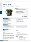
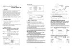
Moxa EtherDevice™ Router EDR-G903/G902 Hardware Installation Guide Second Edition, July 2011 2011 Moxa Inc. All rights reserved. Reproduction without permission is prohibited. Fl.4, No.135, Lane 235, Pao-Chiao Rd. Shing Tien City, Taipei, Taiwan, R.O.C. TEL: +886-2-8919-1230 P/N: 1802009030011 Package Checklist The Moxa EtherDevice Router is shipped with the following items. If any of these items is missing or damaged, please contact your customer service representative for assistance. 1 EtherDevice Router Hardware Installation Guide CD-ROM with User’s Manual and Windows utility Moxa product warranty statement RJ45 to DB9 console port cable Protective caps for unused ports Features Advanced Industrial Networking Capability Router/Firewall/VPN all in one. High performance Gigabit copper/fiber combo port. Supports 1 WAN, 1 LAN, and 1 user-configurable WAN or DMZ interface (EDR-G903). Supports 1 WAN and 1 LAN (EDR-G902) Firewall with Quick Automation Profile for Fieldbus protocols. Network address translation (N-to-1, 1-to-1, and port forwarding). Intelligent PolicyCheck and SettingCheck tools. -40 to 75°C operating temperature (T models). -2- Panel Views of EtherDevice Router Front Panel (G903) Front Panel (G903): 1. 2. 3. 4. 5. 6. WAN1, DMZ/WAN2, LAN port: 10/100/1000 BaseT(X) or 100/1000Base SFP slot combo ports Power input PWR1 LED Power input PWR2 LED Fault LED 10/100/1000BaseT(X) LED indicator LED for DMZ/WAN2 port Front Panel (G902) Front Panel (G902): 1. 2. 3. 4. 5. -3- WAN, LAN port 10/100/1000 BaseT(X) or 100/1000Base SFP slot combo ports Power input PWR1 LED Power input PWR2 LED Fault LED 10/100/1000BaseT(X) LED indicator Top Panel Top Panel: 1. 2. 3. 4. Rear Panel Grounding screw 4-pin terminal block for PWR 1, PWR 2 4-pin terminal block for DI and Relay RS-232 console port Rear Panel: 1. Terminal block 2. DIN-Rail kit -4- Mounting Dimensions (unit = mm) DIN-Rail Mounting The aluminum DIN-Rail attachment plate should already be fixed to the back panel of the EtherDevice Router when you take it out of the box. If you need to reattach the DIN-Rail attachment plate to the EtherDevice Router, make sure the stiff metal spring is situated towards the top, as shown in the following figures. STEP 1—Insert the top of the DIN-Rail into the slot just below the stiff metal spring. STEP 2—The DIN-Rail attachment unit will snap into place as shown in the following illustration. To remove the EtherDevice Router from the DIN-Rail, simply reverse Steps 1 and 2 above. -5- Wiring Requirements WARNING Do not disconnect modules or wires unless power has been switched off or the area is known to be non-hazardous. The devices may only be connected to the supply voltage shown on the type plate. The devices are designed for operation with a Safety Extra-Low Voltage. Thus, they may only be connected to the supply voltage connections and to the signal contact with the Safety Extra-Low Voltages (SELV) in compliance with IEC950/ EN60950-1/ VDE0805. ATTENTION This unit is a built-in type. When the unit is installed in another piece of equipment, the equipment enclosing the unit must comply with fire enclosure regulation IEC 60950-1/EN60950-1 (or similar regulation). ATTENTION Safety First! Be sure to disconnect the power cord before installing and/or wiring your Moxa EtherDevice Router. Calculate the maximum possible current in each power wire and common wire. Observe all electrical codes dictating the maximum current allowable for each wire size. If the current goes above the maximum ratings, the wiring could overheat, causing serious damage to your equipment. Please read and follow these guidelines: Use separate paths to route wiring for power and devices. If power wiring and device wiring paths must cross, make sure the wires are perpendicular at the intersection point. NOTE: Do not run signal or communications wiring and power wiring through the same wire conduit. To avoid interference, wires with different signal characteristics should be routed separately. You can use the type of signal transmitted through a wire to determine which wires should be kept separate. The rule of thumb is that wiring sharing similar electrical characteristics can be bundled together You should separate input wiring from output wiring We advise that you label the wiring to all devices in the system. Grounding the Moxa EtherDevice Router Grounding and wire routing help limit the effects of noise due to electromagnetic interference (EMI). Run the ground connection from the ground screw to the grounding surface prior to connecting devices. -6- ATTENTION This product is intended to be mounted to a well-grounded mounting surface such as a metal panel. Wiring the Relay Contact The EtherDevice Router has one set of relay outputs. This relay contact uses one contacts of the terminal block on the EtherDevice Router’s top panel. Refer to the next section for detailed instructions on how to connect the wires to the terminal block connector, and how to attach the terminal block connector to the terminal block receptor. In this section, we illustrate the meaning of the contact used to connect the relay contact. FAULT: The two right contacts of the 4-pin terminal block connector are used to detect user-configured events. The two wires attached to the fault contacts form an open circuit when a user-configured event is triggered. If a user-configured event does not occur, the fault circuit remains closed. Wiring the Redundant Power Inputs The EtherDevice Router has two sets of power inputs—power input 1 and power input 2. The top and front views of one of the terminal block connectors are shown here. STEP 1: Insert the negative/positive DC wires into the V-/V+ terminals, respectively. STEP 2: To keep the DC wires from pulling loose, use a small flat-blade screwdriver to tighten the wire-clamp screws on the front of the terminal block connector. STEP 3: Insert the plastic terminal block connector prongs into the terminal block receptor, which is located on the EtherDevice Router’s top panel. -7- Wiring the Digital Inputs The EtherDevice Router has one set of digital input, DI. The DI consists of two left contacts of the 4-pin terminal block connector on the EtherDevice Router’s top panel, which are used for the DC inputs. The top and front views of one of the terminal block connectors are shown here. STEP 1: Insert the negative (ground)/positive DI wires into the ┴/I terminals, respectively. STEP 2: To keep the DI wires from pulling loose, use a small flat-blade screwdriver to tighten the wire-clamp screws on the front of the terminal block connector. STEP 3: Insert the plastic terminal block connector prongs into the terminal block receptor, which is located on the EDR-G903’s top panel. Communication Connections Each EtherDevice Router has 2 types of communication port: 1 RJ45 console port (RS-232 interface) 3 combination 10/100/1000T(X)/1000BaseSFP ports (EDR-G903) 1 combination 10/100/1000T(X)/1000BaseSFP port and 1 10/100/1000T(X) Ethernet port (EDR-G902) RS-232 Connection The EtherDevice Router has one RS-232 (10-pin RJ45) console port, located on the top panel. Use either an RJ45-to-DB9 (see the cable following wiring diagrams) to connect the EtherDevice Router’s console port to your PC’s COM port. You may then use a console terminal program, such as Moxa PComm Terminal Emulator, to access the EtherDevice Router’s console configuration utility. RJ45 (10-pin) Console Port Pinouts Pin 1 2 3 4 5 6 7 8 9 10 Description -----DSR RTS -----TxD RxD GND CTS DTR ------ -8- RJ45 (10-pin) to DB9 (F) Cable Wiring 10/100/1000BaseT(X) Ethernet Port Connection The 10/100/1000BaseT(X) ports located on Moxa EtherDevice Router’s front panel are used to connect to Ethernet-enabled devices. Most users will choose to configure these ports for Auto MDI/MDI-X mode, in which case the port’s pinouts are adjusted automatically depending on the type of Ethernet cable used (straight-through or cross-over), and the type of device (NIC-type or HUB/Switch-type) connected to the port. In what follows, we give pinouts for both MDI (NIC-type) ports and MDI-X (HUB/Switch-type) ports. We also give cable wiring diagrams for straight-through and cross-over Ethernet cables. 10/100Base T(x) RJ45 Pinouts MDI Port Pinouts Pin 1 2 3 6 Signal Tx+ TxRx+ Rx- MDI-X Port Pinouts Pin 1 2 3 6 Signal Rx+ RxTx+ Tx- 1000BaseT RJ45 Pinouts Pin 1 2 3 4 5 6 7 8 MDI BI_DA+ BI_DABI_DB+ BI_DC+ BI_DCBI_DBBI_DD+ BI_DD- MDI-X BI_DB+ BI_DBBI_DA+ BI_DD+ BI_DDBI_DABI_DC+ BI_DC- -9- 8-pin RJ45 RJ45 (8-pin) to RJ45 (8-pin) Straight-Through Cable Wiring RJ45 (8-pin) to RJ45 (8-pin) Cross-Over Cable Wiring 100 BaseFX or 1000BaseSFP Fiber Port The Gigabit Ethernet ports on the EtherDevice Router are SFP slots, which require 100BaseFX SFP or Gigabit mini-GBIC fiber transceivers to work properly. Moxa provides complete transceiver models for various distance requirements. The concept behind the LC port and cable is quite straightforward. Suppose you are connecting devices I and II. Unlike electrical signals, optical signals do not require a circuit in order to transmit data. Consequently, one of the optical lines is used to transmit data from device I to device II, and the other optical line is used to transmit data from device II to device I, for full-duplex transmission. Remember to connect the Tx (transmit) port of device I to the Rx (receive) port of device II, and the Rx (receive) port of device I to the Tx (transmit) port of device II. If you make your own cable, we suggest labeling the two sides of the same line with the same letter (A-to-A and B-to-B, as shown below, or A1-to-A2 and B1-to-B2). LC-Port Pinouts LC-Port to LC-Port Cable Wiring - 10 - ATTENTION This is a Class 1 Laser/LED product. To avoid causing serious damage to your eyes, do not stare directly into the Laser Beam. LED Indicators The front panel of the Moxa EtherDevice Router contains several LED indicators. The function of each LED is described in the following table: LED Color PWR1 AMBER PWR2 FAULT AMBER RED AMBER State On Off Power is not being supplied to power input P1 on the main module. On Power is being supplied to power input P2 on the main module. Off Power is not being supplied to power input P2 on the main module. On When a user-configured event is triggered. Off When a user-configured event has not been triggered. On TP or FX port’s 10/100 Mbps link is active. Blinking Data is being transmitted at 10/100 Mbps. Off 10/100/1000M On GREEN WAN/DMZ (EDR-G903 only) AMBER GREEN Description Power is being supplied to power input P1 on the main module. TP or FX port’s 10/100 Mbps link is inactive. TP or FX port’s 1000 Mbps link is active. Blinking Data is being transmitted at 1000 Mbps. Off TP or FX port’s 1000 Mbps link is inactive. On The WAN2/DMZ port is set to the “WAN” function. Off The WAN2/DMZ port is disabled. On The WAN2/DMZ port is set to the “DMZ” function. Off The WAN2/DMZ port is disabled. - 11 - Specifications Technology Standards IEEE 802.3 for 10BaseT IEEE 802.3u for 100BaseT(X) and 100BaseFX IEEE 802.3ab for 1000BaseT(X) IEEE 802.3z for 1000BaseX Protocols SNMPv1/v2c/v3, DHCP Server/Client, TFTP, NTP, HTTP, HTTPS, Telnet, SSH, Syslog, SMTP, LLDP, PPPoE, PPTP, Dynamic DNS, QoS (Quality of Service) Flow Control IEEE 802.3x flow control, back pressure flow control Interface RJ45 Ports 10/100/1000BaseT(X) auto negotiation speed Fiber Ports 100/1000BaseSFP slot LED Indicators PWR1, PWR2, FAULT, 10/100/1000M, DMZ/WAN Alarm Contact One relay output with current carrying capacity of 1 A @ 24 VDC Digital Input 1 input • For state “1”: +13 to +30 V • For state “0”: -30 to +3 V • Max. input current: 8 mA Power Input Voltage 12/24/48 VDC redundant dual inputs Connection Removable terminal block Overload Current Protection Present Reverse Polarity Protection Present Physical Characteristics Housing Metal Dimensions (W × H × D) 51.2 × 152 × 131.1 mm (2.02 × 5.98 × 5.16 in) Weight 1250g Installation DIN-Rail mounting Environmental Limits Operating Temperature 0 to 60°C (32 to 140°F), standard models -40 to 75°C (-40 to 167°F) for -T models Storage Temperature -40 to 85°C (-40 to 185°F) Operating Humidity 5 to 95% (non-condensing) Regulatory Approvals Safety UL 508(Pending) EMI FCC Part 15, CISPR (EN55022); class A EMS IEC 61000-4-2 (ESD), level 3; - 12 - IEC 61000-4-3 (RS), level 3; IEC 61000-4-4 (EFT), level 3; IEC 61000-4-5 (Surge), level 3; IEC 61000-4-6 (CS), level 3 Shock IEC60068-2-27 Free Fall IEC60068-2-32 Vibration IEC60068-2-6 WARRANTY 5 years Technical Support Contact Information www.moxa.com/support Moxa Americas: Toll-free: 1-888-669-2872 Tel: +1-714-528-6777 Fax: +1-714-528-6778 Moxa China (Shanghai office): Toll-free: 800-820-5036 Tel: +86-21-5258-9955 Fax: +86-10-6872-3958 Moxa Europe: Tel: +49-89-3 70 03 99-0 Fax: +49-89-3 70 03 99-99 Moxa Asia-Pacific: Tel: +886-2-8919-1230 Fax: +886-2-8919-1231 - 13 -