1
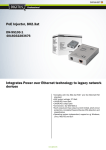
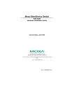
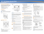
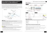
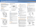
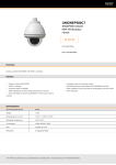
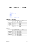
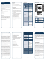
1.4 Specification 1.3 Features Product 8-Port RJ-45 LED System: Power x 1 (Green) Per PoE Port: PoE ready / in-use x 4 (Green) Network Cable 10Base-T: 2-Pair UTP Cat. 5 up to 100m (328ft) 100Base-TX: 2-Pair UTP Cat. 5 up to 100m (328ft) 1000Base-T: 4-Pair UTP Cat. 5e, 6, up to 100m (328ft) EIA/TIA-568 100-ohm STP (100m, 328ft) DC 52V power over RJ-45 Ethernet cable to devices with Ethernet port Power Adapter x 1 PoE power up to 30.8 Watts (802.3at PoE) / 15.4 Watts (802.3af PoE) for each PoE ports Power Cord x 1 Remote power feeding up to 100m If any of these pieces are missing or damaged, please contact your dealer immediately, if possible, retain the carton including the original packing material, and use them against to repack the product in case there is a need to return it to us for repair. Full power support for per PoE port Automatically detect powered device (PD) Circuit protection between ports prevents power interference Dimension (H x W x D) 26 x 70 x 97mm Weight 220g Power Requirement DC 52V~56V Power over Ethernet -1- 1.2 About the Power over Ethernet Injector Hub The PLANET HPOE-460 is the next generation 4-Port Gigabit IEEE 802.3at High Power PoE injector Hub, features both IEEE 802.3af and High Power IEEE 802.3at Power over Ethernet (PoE) that combines up to 30 Watts power output and data per port over one CAT 5E / 6 Ethernet cable. It is designed specifically to satisfy the growing demand of higher power consuming network PD (powered devices) such as PTZ (Pan, Tilt & Zoom) / Speed Dome network cameras, multi-channel (802.11a/b/g/n) wireless LAN access points and other network devices by providing double amount of PoE power than conventional 802.3af PoE PSE. The HPOE-460 is installed between a regular Ethernet Switch and the powered devices; it injects power to the PDs without affecting data transmission performance. It offers a cost effective and quick solution to upgrade network system to IEEE 802.3af / IEEE 802.3at Power over Ethernet system without replacing the existing Ethernet Switch. There are 8 RJ-45 STP ports on the front panel of the HPOE-460, half of the ports on right panel function as “Data input" and the other half on left panel function as "PoE (Data and Power) output". The 4 "PoE (Data and Power) output” ports are also the power injectors that transmit DC voltage to the CAT. 5/5e/6 cable and transfer data and power simultaneously between the Injectors and Splitters. -2- PoE Power Supply Type Mid-Span PoE Power Output IEEE 802.3af Per Port DC 52V 15.4 Watts IEEE 802.3at Per Port DC 52V 30.8 Watts -3- -5- 4/5(+), 7/8(-) PoE Power Budget 120 Watts LED indicator power input indication Number of 802.3af PD Class 0, 1, 2, 3 can be powered 4 FCC Part 15 Class B, CE Number of 802.3at PD Class 1, 2, 3 can be powered 4 100~240V AC, 50/60Hz, 2A universal power supply adapter with DC 52V / 2.31A power output Number of 802.3at PD Class 0, 4 can be powered 4 Desktop palm size, wall mountable Standards Conformance Plug & play Standards Compliance IEEE 802.3 10Base-T Ethernet IEEE 802.3u 100Base-TX Fast Ethernet IEEE 802.3ab 1000Base-T Gigabit Ethernet IEEE 802.3af Power over Ethernet IEEE 802.3at Power over Ethernet Enhancement Regulation Compliance FCC Part 15 Class B, CE Standard Compliance IEEE 802.3 10Base-T IEEE 802.3u 100Base-TX IEEE 802.3ab 1000Base-T IEEE 802.3af Power over Ethernet IEEE 802.3at Power over Ethernet Enhancement 1 2 IEEE 802.3at 4-Port High Power PoE Injector Hub PoE in-Use 4 3 2 1 PWR 52V~56V DC CAUTION Remove “DATA & PWR” Connection before power on. LED Definition: LED Color Function Power Green Lights to indicate that the HPOE-460 has power. PoE Ready / In-Use Green Lights to indicate the port is providing 52V DC in-line power. -7- Power Pin Assignment Hardware DATA 10/100/1000Mbps 4 Up to 4 IEEE 802.3at / 802.3af devices powered Data Rate 3 IEEE 802.3at and IEEE 802.3af Power over Ethernet Mid-Span PSE 3 User's Manual x 1 Power over Ethernet “Data” Input Ports 4 x RJ-45 Interface “Data+Power” 4 x RJ-45 Output Ports DATA & PWR 4-Port 10/100/1000Mbps “Data + Power output” 2 Thank you for purchasing our HPOE-460 4-Port Gigabit IEEE 802.3at High Power over Ethernet Injector Hub, the High Power over Ethernet Injector Hub package shall contains following contents: 1 4-Port 10/100/1000Mbps “Data input” High Power over Ethernet Injector Hub x 1 1.5 Product Outlook Hardware 1.1 Checklist Check the contents of your package for following parts: HPOE-460 4 1. Introduction Environment Operating Temperature 0 ~ 50 Degree C Storage Temperature -10 ~ 70 Degree C Humidity 5 ~ 95% (Non-condensing) 2. Hardware Installation This product provides three different running speeds – 10Mbps, 100Mbps and 1000Mbps in the same device and automatically distinguishes the speed of incoming connection. This section describes the hardware features of HPOE460. Before connecting any network device to the HPOE460, read this chapter carefully. 2.1.Before Installation Before your installation, it is recommended to check your network environment. If there has any IEEE 802.3af / 802.3at device which needs power on, the HPOE-460 provides you a way to supply power for this Ethernet device conveniently and easily. The HPOE-460 equips with an AC-DC adapter with DC 52V input and injects this DC power into the pin of the twisted pair cable (pair 4, 5 and pair 7, 8). If there is very difficult to find a power socket for AC-DC Adapter of your Non-IEEE 802.3af / 802.3at networked device, the HPOE-460 and POE-162S / IPOE-162S can provide you a way to supply DC power for this Ethernet device conveniently and easily. The 10Mbps or 100Mbps and 1000Mbps speed, duplex mode from Data port of HPOE-460 depends on which Ethernet device attached. -4- -6- -8- 2.2 HPOE-460 and POE-162S, the IEEE 802.3at Injector / Splitter and Equipment Installation For the places hard to find the power inlet, the HPOE-460 and IEEE 802.3at High Power over Ethernet Splitter (POE-162S / IPOE-162S) provides the easiest way to power your Ethernet devices such as IP Camera on the ceiling and the Wireless Access Point installed on the top of the building. With 4 10/100/1000Base-T Gigabit Ethernet ports, the HPOE-460 supports full 52V DC power for any remote IEEE 802.3af / 802.3at powered device (PD). To control the power system of your networking devices, the HPOE-460 can directly co-work with PoE IP phone to build VoIP telephony network in the office. Furthermore, the HPOE-460 can be directly connected to any third party IEEE 802.3af / 802.3at compliant devices installed 100 meters away. 3. Troubleshooting This chapter contains information to help you solve issue. If the High Power over Ethernet Injector Hub is not functioning properly, make sure the High Power over Ethernet Injector Hub was set up according to instructions in this manual. How to let my Non IEEE 802.3af / 802.3at network devices work with HPOE-460? Solution: You can use PLANET Power over Ethernet Splitter, such as PLANET POE-162S / IPOE-162S to work as a power transformer between HPOE-460 and Non IEEE 802.3af / 802.3at devices. The POE-162S and IPOE-162S provide 12V DC and 24V DC voltage output through DIP switch. The HPOE-460 PoE LED is not light Solution: Check the cable connection between HPOE-460 and IEEE 802.3af / 802.3at devices. -9- - 11 - 802.3at PoE PTZ / Speed Dome IP Camera 802.3af PoE IP Camera Why can not power my PoE device on when connect with HPOE-460? Appendix A Networking Connection Solution: RJ-45 Pin Assignments Power 15W PoE HPOE-460 30W PoE PoE PoE 802.3at PoE Splitter a N 8-Port Gigabit Switch 30W 2.Please check and assure the device that fully complied with IEEE 802.3af and IEEE 802.3at standard. DC 802.3at PoE Multi-Channel / High Power Wireless AP 1.Please check the cable type of the connection from HPOE-460 to the other end. The cable should be an 8-wire UTP, Category 5/5e/6, EIA568 cable within 100 meters. A cable with only 4-wire, short loop or over 100 meters, all will affect the power supply. 802.3at PoE Splitter+ Non-PoE Device PoE 1000Base-T UTP with PoE 1000Base-T UTP DC Power Line (DC) Power Line 1. According to IEEE 802.3af and IEEE 802.3at standard, the HPOE-460 will not inject power to the cable if not connect to IEEE 802.3af and IEEE 802.3at standard devices. 2. Due to the capability of IEEE 802.3af and IEEE 802.3at standard, the HPOE460 can directly connect with any IEEE 802.3af or IEEE 802.3at standard compliant end-nodes. - 10 - RJ-45 Connector pin assignment Contact MDI MDI-X 1 BI_DA+ BI_DB+ 2 BI_DABI_DB3 BI_DB+ BI_DA+ 4 BI_DC+ BI_DD+ 5 BI_DCBI_DD6 BI_DBBI_DA7 BI_DD+ BI_DC+ 8 BI_DDBI_DCImplicit implementation of the crossover function within a twisted-pair cable, or at a wiring panel, while not expressly forbidden, is beyond the scope of this standard. Figure 2-1: HPOE-460 Application Topology Note 1000Mbps, 1000Base-T 10/100Mbps, 10/100Base-TX RJ-45 Connector pin assignment MDI MDI-X Media MDI-X Media Dependant Contact Dependant Interface Interface -Cross 1 2 3 4, 5 6 7, 8 - 12 - Tx + (transmit) Rx + (receive) Tx - (transmit) Rx - (receive) Rx + (receive) Tx + (transmit) IEEE 802.3af / 802.3at DC 48V / 52V Rx - (receive) Tx - (transmit) IEEE 802.3af / 802.3at DC 0V - 13 - The standard RJ-45 receptacle / connector There are 8 wires on a standard UTP/STP cable and each wire is color-coded. The following shows the pin allocation and color of straight cable and crossover cable connection: Straight Cable 1 2 3 4 5 6 7 8 1 2 3 4 5 6 7 8 SIDE 1 SIDE 2 SIDE 1 SIDE 2 1 = White/Orange 2 = Orange 3 = White/Green 4 = Blue 5 = White/Blue 6 = Green 7 = White/Brown 8 = Brown 1 = White/Orange 2 = Orange 3 = White/Green 4 = Blue 5 = White/Blue 6 = Green 7 = White/Brown 8 = Brown Crossover Cable SIDE 1 SIDE 2 1 2 3 4 5 6 7 8 SIDE 1 1 2 3 4 5 6 7 8 SIDE 2 1 = White/Orange 2 = Orange 3 = White/Green 4 = Blue 5 = White/Blue 6 = Green 7 = White/Brown 8 = Brown 1 = White/Green 2 = Green 3 = White/Orange 4 = Blue 5 = White/Blue 6 = Orange 7 = White/Brown 8 = Brown Figure A-1: Straight-Through and Crossover Cable Please make sure your connected cables are with same pin assignment and color as above picture before deploying the cables into your network. Energy Saving Note of the Device This power required device does not support Standby mode operation. For energy saving, please remove the power cable to disconnect the device from the power circuit. Without removing power cable, the device wills still consuming power from the power source. In the view of Saving the Energy and reduce the unnecessary power consuming, it is strongly suggested to remove the power connection for the device if this device is not intended to be active. - 14 -