1
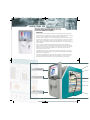
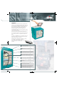
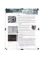
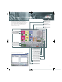
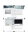
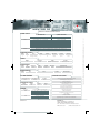
Mentor12 EN 2
12/4/10
00:45
Página 1
Mentor12 EN 2
12/4/10
00:46
Página 2
MENTOR 12
“A l l i n O n e ” S y s t e m f o r e l e c t r o m e c h a n i c a l , e l e c t r o n i c ,
and numerical protection relay t e s t i n g
INNOVATION
The new Mentor 12 universal platform revolutionizes the traditional relay testing concepts. With
more than 20 years in designing and developing test equipment, EuroSMC has launched a product
which exceeds the expectations of the most demanding professionals in this field.
The Mentor 12 has everything you need to test relays of any type, including the routine procedures
and results saved in memory by the user for later repetition and reference. No external computer is
required, except for existing and upcoming remote control applications that are not part of the
built-in software. Also incorporated is an auxiliary voltage supply source to energize the relay under
test when required.
Based on the success obtained from the PTE family of relay testing products, EuroSMC has
equipped the Mentor 12 with a fast, powerful yet simple manual control interface that allows the
expert user to verify the response of any relay in seconds. For the more complex or repetitive jobs,
however, a full set of pre-defined, fully configurable test tools will assist the operator for an
efficient, safe and error-free testing.
Your Mentor 12 will never become obsolete because all its functional elements are completely
programmable. You can upgrade its software over the internet and install plug-and-play hardware
options with no external assistance.
Ultra-compact output amplifiers, energy saving system, self-regulated ventilation, automatic autoresetting protections with dynamic status reports, safety indicators, etc., we have charged the
Mentor 12 with state-of-the-art features to keep it in perfect shape and ready at all times.
Swivel Touch-Sensitive
800x600 LCD. Built-in Windows
CE® computer .
Rotary encoder for adjustment
of test values and sliders.
Ergonomic custom case with
anti-slip coating and transport
handles.
2
Mentor12 EN 2
12/4/10
00:46
Página 3
SIMPLICITY
The Mentor 12 is controlled via a touch screen panel and a
rotary selector. An external mouse and keyboard can also be
used if desired. The multilingual menus, neat and complete,
appear to know what you want to do next. The entire test
process and test results are immediately displayed in
numerical and graphic forms, with a complete set of
feedback indicators and a real-time representation of power
vectors. Easier, impossible.
You only need turn on the Mentor 12, connect it to the relay,
and select the desired test on the menu. You will see the
process and the results on the screen. Now, name it and save
it so you can repeat the test or examine the results in the
future.
If you have a COMTRADE file stored on a USB pen drive, just
plug it into the Mentor 12 and it will reproduce the signal
onto the relay in a matter of seconds.
The VGA connector can be used, for example, to cast the
screen image on the wall with an overhead
projector. This provides a simple, convenient way
to train other people on the Mentor 12’s
operation.
Fuse-protected AC power input.
Programmable Auxiliary DC supply with electronic
protection.
Two three-channel bays for up to six voltage amplifiers
with independent neutral, reversible to current mode.
12 binary inputs with automatic dry/voltage contact
detection. Software-configured logical processing.
High-accuracy voltage / current measurement input.
8 binary outputs. Software-configurable relay or open
collector modes.
Two three-channel bays for up to six isolated current
amplifiers with independent neutral.
Connectivity set with 6 low level signal outputs, GPS
antenna, digital expansion port, Centronics, RS-232,
Ethernet LAN, 2xUSB, VGA, Mouse, Keyboard.
3
Mentor12 EN 2
12/4/10
00:46
Página 4
MENTOR 12
POWER
A state-of-the-art, fully programmable digital waveform generation engine constitutes the heart of
the Mentor 12. It is able to control twelve independent low-level signal paths to the output section,
producing extremely accurate signals with a 3-kHz bandwidth. These signals are then driven to the
output amplifiers for a stable, distortion-free 100 VA testing power. Prior to being amplified, these
signals are also available at the low-level output connectors to test and calibrate transducers,
energy meters and sensor- or Rogowski coil-based protective relays, as well as to be externally
amplified for applications that require greater current or voltage limits.
Low Level Output Connectors
The output amplifiers of the Mentor 12 deliver a stable and efficient output, with a power curve
adapted to the most demanding test conditions. The unit can be charged with up to 6 current and 6
voltage amplifiers, each of which supply top-quality 100 VA/W permanent power simultaneously.
The resulting 1,200 VA aggregated power allows for the complete three-phase testing of two relays
at the same time, including the logical scheme and messaging functions, simulated and recorded
by the 8 binary outputs and 8 inputs available in the Mentor 12.
FLEXIBILITY
You might not need twelve channels right now. Start with a smaller configuration and add
more channels when you need them. The Mentor 12’s amplifiers
are plug and play. You just remove the unit’s side cover, slide the
amplifier(s) in, turn the unit on and continue working. The new
amplifiers will be recognized and added to all the test and
configuration screens by the Mentor 12 automatically.
Regardless the number of amplifiers in your Mentor 12, you can
also combine them in series and in parallel to attain greater
voltage and current levels. The output configuration screen
displays a menu with all the possible combinations and a visual guide to help you at
connecting the relay. There is no need to calculate partial current, voltage or phase angle
values as the Mentor 12 manages and shows each group of combined channels as if it were a
single “virtual “one.
Combining two voltage channels in series
Furthermore, each voltage amplifier can be switched to current mode by a simple touch on
the configuration screen. This feature allows, for example, to convert a Mentor 12 3v3i (3
voltage + 3 current channels) to a six-current test set when the need for testing three-phase
differential relay arises.
You can accurately measure the output from a transducer, an energy meter or any other
measurement device by connecting it to the analogue or binary inputs while injecting known
quantities with the Mentor 12.
PRODUCTIVITY
The Mentor 12’s human interface is organized to complete the job safely and accurately in the
shortest possible time. Locating the necessary controls and the relevant test information will
take just a few seconds to the untrained expert. The Basic Control virtual panel has been
designed especially for him. Adjusting a few values and testing a handful of trip points in the
relay is a snap, thanks to the touch-sensitive panel and the rotary knob. There is no need to
even look at the relay, as its response is displayed on the control screen in real time.
COMTRADE transient playback
4
Do you need to reproduce transient fault recordings? The Mentor 12 includes this feature as
standard. You only need to copy your COMTRADE files into a USB pendrive, plug it into the unit
and press Playback. If you want, you can assign each current and voltage signal in the
recording to specific current and voltage channels for the playback. And, naturally, you can
also map the recorded binary information and the response of the relay to any of the binary
outputs and inputs in the Mentor 12 respectively, discard the unneeded signal’s sections or
adjust the best transformation ratio for the playback. Now, press Playback and examine the
streamed signals and the relay’s reactions in the screen.
Mentor12 EN 2
12/4/10
00:46
Página 5
Timer operation setup and
preferences
The saved collection of user-defined and customized test
routines will provide a valuable asset of ready-to-use test tools
for each relay type and protective function. You only need to
choose one from the list in the Results Manager and press
Execute. The Mentor 12 attaches the results of the last
execution to each test recorded.
External measurement
configuration
Event logger
Basic Control virtual panel
Control panel for voltage and
current outputs
Adjustment of test quantities,
phase angles and frequencies
Channel selection, memory and
dynamic fault shortcuts
Output On/off indicators
Indicator / access to the
alarm reports
Multifunction display (timer,
pulse, analogue, etc.)
Test Setup & Results Storage Management Menu
Binary outputs activation
/status
Auxiliary DC supply control /
setup
Remote control activation /
setup
Binary inputs status indicators
Adjustment digit selection
5
Mentor12 EN 2
12/4/10
00:46
Página 6
MENTOR 12
ADVANCED TEST FUNCTIONS
The Advanced Control button gives way to a number of powerful, yet easy to use functions to locate
and test trip points in any type of relay. Each function features a graphical representation of the test
with fields containing the adjustable parameters. The State Sequencer –a simple programmable
multi-step tool– and the Binary Search are among the expert’s favorites. A three-state Fault
function, a Single/Double Ramp, a Pulse Ramp and the Transient Playback complete the Advanced
set.
Fault function setup screen
You immediately realize what each function does when you see it. Setting up the test is like filling
out a form with fields on the function’s sections, each value being instantaneously checked and
validated by the Mentor 12. You can also determine how the relay’s output must be processed,
discarding irrelevant trips or specifying a combination of contacts as required for trip validation.
Press Execute now. The test progress is displayed in an oscillographic fashion, with electrical values
evolving along the ramp and trip points being stamped on the timeline as they take place. At the
end, type a name and a brief description and save it all for future use. Since storage takes place on
removable USB pendrives, your capacity is virtually unlimited, as is your freedom to transfer the
data to your PC or to another Mentor 12.
Binary Search progress and results display
Binary Search function setup
AVAILABLE OPTIONS
Like any other products manufactured by EuroSMC, the Mentor 12 includes all the accessories
required for the job. However, a range of optional components is also offered to better match your
particular needs or preferences.
Output Channels
One of the greatest advantages of the Mentor 12 is its modular design. You can start with a basic 6channel unit and add more channels later on. The plug and play technology makes adding or
replacing channels an easy operation, with no need to return the unit to the factory.
6
Mentor12 EN 2
12/4/10
00:46
Página 7
The minimum configuration is three 0-25A current channels
and three 0-150V voltage channels that can be individually
turned into 0-5A current from the configuration menu. Each
one provides 100 VA permanent power concurrently, and works
in the 0 (DC) to 3,000 Hz frequency bandwidth. This basic sixchannel configuration provides a complete three-phase V/I
test platform with the possibility of setting up six simultaneous
current sources for differential relay testing.
Nylon Bag
Ideal option for short-distance transportation. 20-mm padding for
adequate protection inside the car’s trunk, adding no significant
weight to the equipment. The screen, connections panel and
ventilation grid can be uncovered, so there is no need to extract the
Mentor 12 from the bag for testing.
GPS / IRIG-B synchronization
As the Mentor 12 is preinstalled with an external antenna
connector, you can always order the optional GPS receiver
module and plug it inside the unit for end-to-end testing. If the
conditions are not suitable for adequate GPS reception, you can
choose the IRIG-B interface to take the time reference from the
existing bus in the substation instead.
Software
The Mentor 12’s standard equipment build up one of the most
advanced basic configurations available on the market.
The intrinsic possibilities of this top-technology product are
virtually unlimited. Therefore, we recommend you refer to your
equipment supplier for additional test modules and remote
control applications by EuroSMC or third-party vendors.
We at EuroSMC S.A. appreciate your interest and will be happy
to answer any questions that you may post on the Mentor 12 or
any other product in our catalogue.
External Software
For a high degree of automation of the
test process, consider our optional
Eurotest® RTS relay testing software for
Windows®. This application provides a
comprehensive and continuously
updated library of pre-defined test
routines for the most common relay
types, and a test definition assistant to
create custom routines for double-click
testing and reporting. Eurotest® RTS
stores all the test definitions and
results in a Microsoft Access®compatible database and must be run
in an external computer.
Function-specific test modules and
applications are also available at
EuroSMC for special cases like
distance, differential relays, etc.
Typical Mentor 12 hardware configurations
MODEL’S NAME
OUTPUT CHANNELS
TYPICAL APPLICATIONS
3v 3i
6
3 voltage (0-150 V or 0-5 A) + 3 current
channels (0-25 A), with 100 VA each.
Single- and three-phase testing of any type of relay, transducers and meters. Up to
600 VA total output power. Full-range transient playback.
4v 3i
7
4 voltage (0-150 V or 0-5 A) + 3 current
channels (0-25 A), with 100 VA each.
Adequate for synchronizing relays. Direct three-phase testing with neutral voltage
elements and a current up to 5 A. Capable for testing three phase differential
relays.
4v 4i
8
4 voltage (0-150 V or 0-5 A) + 4 current
channels (0-25 A), with 100 VA each.
A fourth current supply up to 25 A for devices with neutral element. Single phase
test up to 100 A with 400 VA of power. Testing single phase differential relays with
up to 25 A.
3v 6i
9
3 voltage (0-150 V or 0-5 A) + 6 current
channels (0-25 A), with 100 VA each.
Three- phase electromechanical relays. Direct testing of differential relays with
triple windings, maintaining the connection class. Up to 50A current per channel.
6v 3i
9
6 voltage (0-150 V or 0-5 A) + 3 current
channels (0-25 A), with 100 VA each.
Calibration of low voltage measurement converters and energy meters. Fault tests
of high impedance relays, directional detection of differential neutral with high
voltage setting and moderate current setting.
4v 6i
10
4 voltage (0-150 V or 0-5 A) + 6 current
channels (0-25 A), with 100 VA each.
Single- and three-phase testing with high current settings Differential relay testing.
6v 6i
12
6 voltage (0-150 V or 0-5 A) + 6 current
channels (0-25 A), with 100 VA each.
Testing of 2 relays simultaneously. Three-phase transformer differential testing on
quadruple windings.
7
Mentor12 EN 2
12/4/10
00:46
Página 8
MENTOR 12
MENTOR 12 TECHNICAL SPECIFICATIONS
POWER OUTPUT
3-6
Output ranges
0 - 150 V AC / 0 - 5 A AC / 0 - 212 V DC / 0 - 7 A DC
0 - 25 A AC and DC
Power
100 VA continuous @ 37.5 – 150 V AC, 100W
100 VA @ 9.5 A AC, 100 W
Adjustment resolution
5 mV / 0.5 mA
0.5 mA
Reversibility
Yes
No
Accuracy
0.1% of the value ± 0.03% of the range (20-30º) @ 50-60 Hz
Distortion
0.1 % @ 50-60 Hz (resistive load) / 2 % @ 50-60 Hz (maximum inductive load)
Isolation
Yes (from mains and between all channels)
Combined output
Series and Parallel
Frequency
Adjustment range: 0.0 – 2000 Hz / Bandwidth: 3000 Hz / Resolution: 5 µHz / Accuracy: 1 ppm
Phase angle
Range: 0.0 – 359.9º /Accuracy: 0.1º / Resolution: 0.001º
JAACCEN - Version 2
CURRENT AMPLIFIERS
3-6
LOW LEVEL OUTPUTS
NUMBER
TYPE
LEVELS
RANGES
ISOLATION
RESOLUTION
ACCURACY
DISTORTION
6
V
0-10 Vpk (1 mA max.)
1
No
250 µV
0.07 %
0.05 %
TIMERS
NUMBER
RESOLUTION
RANGES
ACCURACY
4
0.1 ms
00000.0001 – 99999.9999 sec.
0.001 % +/- 0.1 ms
BINARY INPUTS
NUMBER
TYPE
THRESHOLDS
RANGES
ISOLATION
RESOLUTION
COUNTER FUNCTION
12
Dry or voltage
1.5, 15 V
+/-400 V (p-p)
6 groups of 2
0.1 ms
Up to 3 kHz. (width: 150 µs) 100 kHz. in 1 group
BINARY OUTPUTS
NUMBER
TYPE
LEVELS
ISOLATION
TIME RESOLUTION
8
Relay or Open Collector
300 Vdc / 300 Vac / 8 A 2000 VA / 240 W
Yes
100 µs
SUPPLIED ACCESSORIES
EXT. MEASUREMENT
Vdc MEASUREMENT INPUT Idc MEASUREMENT INPUT
± 10 V
ACCURACY
Complete set of test leads with 4-mm banana terminals
0.02 %
16 4-mm adapters to U-shape terminal
± 20 mA
1 power cord 260 V/ 16 A
AUXILIAR DC SUPPLY
2-m / 6.5 ft. twisted-pair Ethernet cable
RANGES
POWER
ACCURACY
RIPPLE
48, 125, 250 Vdc
60 W
5%
0.2 %
RS-232 (ActiveSync®) cable
1 set of 15 assorted replacement fuses
1 PS2 adapter for keyboard and mouse
GENERAL
Dimensions
422 x 254 x 511 mm. / 16.6” x 10” x 20.1”
2 adapters for low level outputs
Weight
22.5 kg. / 49.6 lb(6 ch.) – 29.8 Kg /65.6 lb (12 ch.)
1 USB Pen Drive 512 Mb.
Casing
Custom
1 soft organizer bag for cables and accessories
Consumption
Max. 1600 VA. 100 - 260 V AC, 40 – 70 Hz
Display
Color TFT 800 x 600
Control
Touch panel + rotary encoder
Communications
RS-232, 2 x USB, Ethernet, Centronics, PS2, VGA
DISTRIBUTED BY
1 User’s manual
Certificate of calibration
Sturdy ABS transport case with wheels and extensible handle
EuroSMC, S.A.
Polígono industrial P-29, Calle Buril, 69
28400 Collado Villalba. Madrid (Spain).
Tels: +34 91 849 89 80 Fax: +34 91 851 25 53
www.eurosmc.com
e-mail: [email protected]
Please note: Due to the continuous research and development by EuroSMC, specifications in this catalog may be changed without previous notice.
VOLTAGE AMPLIFIERS
Capacity