1
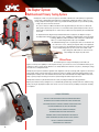
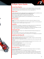
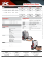
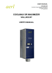
®
E stablished 1981
Advanced Test Equipment Rentals
www.atecorp.com 800-404-ATEC (2832)
PRIMARY INJECTION TEST SYSTEM
Raptor
www.smcint.com
The Raptor System
Multifunctional Primary Testing System
The Raptor is a smart test system designed as the ultimate solution for the main primary test applications
required in the commissioning and maintenance of substations, marking the difference with respect to
existing equipment now being used. This new generation of Primary Injection Test System makes primary
testing easier, faster and more convenient.
The system consists of a Master unit which can be upgraded with up to three Slave sets which add
further power capacity to the system. The user is not limited to the power initially determined. In case
of more power required, Raptor sets can be added, or what is also very important, be left behind when
not needed.
In comparison with the big and heavy traditional variac-based equipment, the Raptor is designed
incredibly smaller and lighter than its predecessors, combining a revolutionary high current generation
technology, DSP based, with an automatic smart control, in a really transportable set, less than 35 Kg and able to inject up to 15,000 A.
An additional advantage to the easy transport is that sets can be much closer to the devices tested, reducing the length of cables, and a significant
decrease in power losses by eliminating intermediate connections, thanks
to the new loop-through concept. The sets have in the middle a hole
to pass through the cables which are connected to the
load, forming in this way the injection circuit.
Efficient Power
The modern high-tech design of the Raptor system enables the
highest level of injection capability in terms of power and duty cycle, with an ease of use so far unknown in this type of
equipment. A touch-sensitive console allows the user to fully monitor and control the test process, including the storage
of results and test configuration tools.
The Raptor system provides automatic regulation of the magnitude to be injected, being stable regardless of the load or
power supply changes. Current output range is adjusted at all times according to application, taking advantage of the
modularity and versatility of the concentration of measurement and control functions in the Raptor Master unit, with a
unique capacity to adjust the voltage and current required through the number of spire turns used.
The Raptor also includes a powerful measurement section, extending the number of testing applications.
Raptor system includes factory configured tests, to automatically perform a large amount of the most common testing,
just by selecting the appropriate template and start the test. The user has also the possibility to easily make or modify
test templates.
UNIQUE FEATURES
SMALLEST SIZE AND WEIGHT FOR OUTSTANDING PORTABILITY
AUTOMATIC OUTPUT REGULATION WITH DIGITAL TECHNOLOGY
MULTIFUNCTIONALITY FOR MOST PRIMARY INJECTION TESTING
INSTANT COMBINATION OF UNITS BY INFRARED
LOOP-THROUGH HIGH CURRENT TECHNIQUE
FLEXIBLE MODULARITY AND ADAPTABILITY
MODERN, ROBUST AND UPGRADEABLE TECHNOLOGY
SMART HANDHELD CONTROLLER WITH TOUCH SCREEN
RESULTS STORAGE AND REPORTING
PREDEFINED TEST TEMPLATES
2
The Raptor System: Applications
The Hand Held Control Unit, RAPTOR-HH, is the user-friendly interface from which the operator remotely controls and
monitors all the test process. The Raptor HH detects and configures the master and slave units automatically.
It provides an intuitive TFT touch screen, visible even in direct sunlight, with a wheel-and-click control that combined
with the existing test templates makes the test configuration and execution task extremely easy and fast.
The unit saves all the test configurations and results on its own memory, which can be further downloaded to an
external computer through USB connection and the RaptorSync software. This unit only weights 0.4 Kg and it is
developed with an ergonomic design optimized for correct handheld use, and nonslip laterals for a safer grip.
The Raptor HH is connected to the Master through a 5-meter cable that allows the user to stay at a convenient location
while the test set is working much closer to the load. For extreme cases, a 4-meter extender is available as an optional
accessory. The console’s back is magnetized, which allows the user to snap it quickly and safely on any iron surface for
a more comfortable operation.
Other advantages are: data storage and reporting, configuration assistance, software upgrades by internet, simplify
and reduce testing time, easy touch/turn operation, maximum test accuracy.
Test Templates allows the user to just select the appropriate template and start the test. Most common tests available
are: Overcurrent relay, MCB/MCCB, CT Ratio/Phase/Burden, CT ratio/phase with voltage, VT ratio/burden/phase,
Rogowsky CT, PT, contact Resistance, Ground Grid, CT magnetization curve and Knee point, Pulses, Recloser, etc.
The Raptor Current Calculator is included as standard in the Raptor HH console and can also be installed on a PC. It is a
simple to use yet sophisticated tool that allows the user to quickly define the Raptor configuration and the number and
type of cables required as minimum to successfully accomplish a specific high current job, even before leaving the office.
APPLICATIONS
The combination of mobility, adaptability, automatic current regulation, high-tech, ease of use and versatility makes
the Raptor the best system available in the market for all major primary injection testing applications in and around
substations and power plants:
Primary Current Injection Testing
Primary Injection Testing is essential in commissioning and verifying a protection scheme. The secondary injection
test does not check all the components in the system, as it cannot provide the condition of the overall protection
installation, whether CTs have the correct ratio or polarity, or whether the secondary wiring is correct and serviceable,
and it does not mimic the operating conditions in service. Therefore, the Primary injection testing is the only way to
prove correct installation and operation of the entire protection scheme, and the Raptor has been specially designed to
meet all primary testing needs.
The Raptor´s variable output frequency extends the primary testing diagnostic with frequency sweep, offering test
frequencies different from the mains frequency, and thus enhancing its electrical testing capacity. Primary Test involves
the entire circuit; current transformer primary and secondary windings, relays, trip and alarm circuits, circuit breakers
and all wiring are checked. Primary injection tests are carried out after secondary injection tests, to ensure that
problems are limited to the VT’s and CT’s involved, circuit breakers, plus associated wiring, all other equipment in the
protection scheme having been proven satisfactory from the secondary injection tests. Hence it is often the last tests
performed in the commissioning and maintenance process, or after major modifications have been carried out, and
also as an invaluable aid to faultfinding.
3
The Raptor System: Applications
Relay Testing
With the Raptor, primary faults can be simulated to check if protective relays operate correctly; trip times are measured
and registered by the system, with 1 ms resolution. The automatic current regulation, the pre-set current injection, the
injection time control, and the test results storage, provide the user with the most
advanced primary testing tool for protection relays.
Circuit Breaker Testing
It is also essential for the verification of the entire protection scheme to verify live
CB tripping, and CB operating time analysis in combination with total trip time
including the IEDs and CB trip time. Measurements with the Raptor deliver
reliable and repeatable results due to high signal and measurement accuracy.
Current Transformer Testing
The Raptor system has many advanced features – such as powerful measurement
input, to allow performing a complete check of a CT. Through a few seconds
test the following results are obtained: Turns Ratio, phase (polarity) between
primary and secondary of the CT, and burden (Impedance, power and power
factor of the load). It can be also used for testing low power and Rogowski
CTs, checking ratio, phase and burden in VTs, and checking Ratio, Polarity,
short circuit impedance and reactance losses in Power Transformers. Test
templates are also available for Magnetization curve and “knee point” of
a CT.
Recloser and Sectionalizers
Through the high current fault simulation, the Raptor performs automatic test,
detecting and getting opening and reclosing times, number of operations,
partial and total times, of the recloser under test.
Switchgear Testing
Low voltage switchgear and controlgear assemblies require also high current testing
to comply with the relevant product standards, both by assembly manufacturers and
users. The Raptor is also suitable for testing the rated short-time current that the
assembly must withstand, and MCB/MCCBs tripping time performance, both
thermal and short-circuit trips.
Heat Runs
Thanks to the amplifier-based high current generation of the Raptor, it is ideal for
performing heat runs, maintaining the current injection stable throughout long-term
testing, and measuring the corresponding time.
Polarity Testing
The Polarity Tester is a lightweight handheld accessory used to verify the correct wiring
in a quick and simple way, as the Raptor injects a special polarized signal into the primary
side of any transformer (CT, VT, PT, etc). This is especially useful for checking polarities in
remote connections and/or those with difficult access.
Ground Grid Testing
By injecting high current and measuring with the low level voltmeter it is possible to detect
the existence of any bad or eroded contact in the ground grid.
Functionality Updates
The Raptor System will not become obsolete as all functional elements are
programmable. We at SMC keep the end users updated with free new updates and
applications required by market demands. Furthermore, the Master unit is designed
to enable additional functionality with future add-on equipment.
4
The Raptor System: Benefits
Automatic Output Regulation
DSP technology maintains a uniform current waveform even with changing load impedances and speeds testing by
eliminating the manual variac. Every other high current system requires the user to manually set the output current.
It also overcomes heating of the trip elements which caused the current to drop during the test.
Weight and Size
Amazing portability compared to other existing equipment, due to its light weight and small size, that allows one person
to carry it, even in his own car. The modularity allows to carry the minimum units to site.
Easier and cheaper to transport and handle. Each unit has wheels and folding handle.
Reduces the length of cables required as sets can be much closer to the device tested.
Facilitates portability into installations with limited space and/or with difficult access, such as stairs, soft soils,
underground substations, etc.
Multi-Functionality
The Raptor system concentrates many applications and testing assets, offering a time-saving and cost effective
solution.
The Raptor logic system features high-power processors to take care of future requirements, and their functionality can
be readily enhanced by means of firmware upgrades through the Internet.
Expandability
The modular design can accommodate several Raptor Slaves to the Master unit, and the user is not limited to initial
power requirement, being able to upgrade the system at a modest cost for higher power needs.
Sets are immediately assembled and synchronized thanks to infrared technology connectivity, IRDA type, thus saving
time, making the portability even better, and the expandability of the system a simple task.
Loop-through concept
The Loop-through high current secondary concept contributes both with flexible modularity and with lightness and
smaller size of the Raptor.
Unique capacity to adjust the voltage and current required through the number of loop turns used.
Reduces cables connection to the minimum possible, thus reducing power losses, and simplifying the test preparation.
Handheld Control Unit (Raptor HH)
Powerful and smart interface with TFT color Touch Screen to control and monitor the test.
Simplify testing through a automating process and test templates, including the storage of test results, and reducing
testing time. Simply dial up the desired current and inject.
USB connection to a PC, and through RaptorSync application to download reports for further editing, analysis, storing
and printing.
Pre-defined test templates help the user to perform quickly and in a more efficient way the most frequent tests, with
minimal training and preparation. Users can also create their own test templates.
Ethernet connector for software updates.
Reliable high speed Raptor Bus connector, with failure detection and alarms.
On screen calculations and magnitudes conversions.
User´s assistance for system configuration, cable selection and testing.
Measurement section
Voltmeter, Ammeter and Low signal Voltmeter inputs, measures AC and DC signals with phase meter incorporated,
extending the testing performance.
Binary input, voltage or dry contact, to detect trip commands that define the end of some tests.
Timer of 1 ms resolution, with zero current detection, and also configurable as countdown to limit the injection time.
Based on the internal and hardware measurements, selectable calculated measurements can be shown on screen ,
such as Total Power, Apparent and Reactive power, Power factor, Impedance, Reactance, Resistance, Transformation
Ratio and Ratio Error.
5
The Raptor System: Features
MASTER UNIT’S FEATURES
The Raptor MS is the master unit of any Raptor configuration. It provides the connection for the touch screen console and can be used as stand-alone for
primary test applications that do not require extremely high current/power. When slave units are added, the MS will detect them automatically over the infrared
link and will accommodate the system’s parameters with no intervention from the user:
• Regulated high AC current output. Able to inject up to 3.8kA (with 3kVA) indefinitely or 9.5kA (with 2kVA) during 3s. Up to 15kA when combined with one or
more slave units.
• Regulated AC auxilliary output. Working in current mode is capable of injecting up to 9 A indefinitely or 35A for 3s. Working in Voltage mode is capable of
generating voltage up to 200V AC.
• Voltmeter Input. Ranges: 0.2, 2, 20 or 300Vac/dc (auto or manual). Built-in phase angle meter.
• Ammeter input. Ranges: 0.2, 2 or 20Aac/dc (auto or manual). Built-in phase angle meter.
• Low signal Voltmeter. Ranges: 30, 300 or 3000 mVac/dc (auto or manual). Built-in phase angle meter.
• Binary input: Voltage or dry contact with reversible logic (NO, NC) and auto-detection.
• LEDs: Monitor overload, temperature, status of communications, standby, digital input, power output and power supply.
• IRDA interface: Interconnects Slave units to the Master wirelessly.
SLAVE UNIT’S FEATURES
The Raptor SL features toroidal windings that are activated individually by the master unit as the power demand grows, through a sophisticated injection control
that ensures seamless current flow and optimal workload distribution.
The slave Raptor is visually identical to the master unit but lacks the measurement section, the handheld controller and the auxiliary input/output panels. Its
mission is to push an additional 5 kVA power to the high current pass-through secondary. Up to three slaves can be added for up to 15,000 A with a 18-kVA
total injection power. The master unit detects the presence of slaves using infrared communications, so no additional control or power interconnections are
required. The user only needs to pass the current cables across the entire assembly and use it as if it was a single device, in a fully transparent way to the
user. As an added benefit of the pass-through secondary technique, the user can easily multiply the compliance voltage by making more than one turn with the
current conductor around the entire system.
6
The Raptor System: Specifications
GENERAL
RAPTOR-MS
(values @240 Vac, 50 Hz, 1 turn sec. 960 mm , measured 25 cm on each side)
2
HIGH CURRENT OUTPUT
Output Current
Output Voltage
No Load V (0%Imax)
0 - 1.20 Vac - Continuous
3.8 KAac (25%Imax)
0 - 0.81 Vac - Continuous
7.5 KAac (50%Imax)
0 - 0.42 Vac - 3 min
9.5 KAac (Imax)
0 - 0.22 Vac - 3 s
No Load Resolution
25 uVac
Output Frequency
20 - 400 Hz (Power reduction applied at 50 > f > 60 Hz)
Supply
230 V ±10%, 50/60 Hz (single phase)
Weight
35 Kg / 77 lb
Dimensions
550 x 440 x 230 mm / 21 ½” x 17 ½” x 9”
Protections
MCB, overload, temperature, supply, communications, polarity
Sec. hole diameter
85 mm
Transport
Wheels, folding handle, fixed handle
RAPTOR-SL
(values @240 Vac, 50 Hz, 1 sec.turn 960 mm2, measured 25 cm on each side)
LOW CURRENT OUTPUT (not simultaneous with high current output)
HIGH CURRENT OUTPUT
Output Current
Output Current
0 - 35 Aac (0 – 9 Aac continuous)
Voltage Output
0 - 200 Vac
Output Frequency
20 - 400 Hz (Power reduction applied at 50 > f > 60 Hz)
Isolated output
Yes
Protection
fuse
MEASUREMENTS
Secondary Current
(for high current output)
Ranges
0-1 KAac/N; 0-15 KAac/N (n: number of secondary turns)
Resolution
1 Aac, 10 Aac
Accuracy
±0.2% of the value ±0.2% of the range
Phase angle
±0.25º
Ammeter/Low Level Voltmeter
Ammeter Ranges
0 - 0.2 / 0 - 2 / 0 - 20 Aac
Ammeter Resolution
0.1 mAac, 1 mAac, 10 mAac
Ammeter Impedance
<10 mΩ
Voltmeter Ranges
0 - 30 mVac, 0 - 0, 3 Vac, 0 - 3 Vac
Voltmeter Resolution
0.015 mVac, 0.15 mVac, 1.5 mVac
Voltmeter Impedance
>3000 KΩ
Frequency range
20 - 400 Hz
Accuracy
±0.1% of the value ±0.1% of the range
Phase angle
±0.25º
Isolated input
Yes
Voltmeter
Output Voltage
No Load V (0%Imax)
0, 0.79 or 1.59 Vac - Continuous
3.8 KAac (25%Imax)
0, 0.67 or 1.34 Vac - Continuous
7.5 KAac (50%Imax)
0, 0.55 or 1.11 Vac - 3 min
15 KAac (100%Imax)
0, 0.30 or 0.61 Vac – 3 s
COMMUNICATIONS
2 IrDA interfaces
Two channels for master/slaves linking
GENERAL
Supply
230V ±10%, 50/60 Hz (single phase)
Weight
35 kg / 77 lb
Protections
MCB, overload, temperature, supply, communications, polarity
Sec. hole diameter
85 mm / 3 ½”
Transport
Wheels, folding handle, fixed handle
RAPTOR-HH
CONTROL
Display
Transflective high definition color TFT with resistive Touch Panel
Wheel
Rotary Encoder (Wheel and click)
LEDs
Alarm, Connectivity, Power
COMMUNICATIONS
RS-485
Raptor BUS Communication with Raptor-MS
USB
Connection to PC (RaptorSync)
RJ-45
Ethernet for software updates
Ranges
0 - 0.2 / 0 - 2 / 0 - 20 / 0 - 300 Vac
Resolution
0.1 mVac, 1 mVac, 10 mVac, 0.15 Vac
Impedance
>120 KΩ
Frequency range
20 - 400 Hz
Power Supply
Self-powered from Raptor-MS, or with external
power adapter 5 Vdc
Accuracy
±0.1% of the value ±0.1% of the range
Weight
0.4 Kg / 1 lb
Phase angle
±0.25º
Dimensions
110 x 185 x 35 mm / 4” x 7” x 1 ½”
Isolated input
Yes
Case
High quality injection-moulded ABS, strong and ergonomic design, edge
surfaces protected with TPE non-slip material. Magnetic base.
Compliance
The instrument is intended for use in high-voltage substations and
industrial environments.
All EuroSMC products have conformity to CE-marking directives, complies
with IEC and international standards, and are designed and manufactured
in accordance with the requirements of the ISO-9001 Quality Standard
Transport Bag
Nylon soft bag
Connection cable
5 m cable / 16 ½ ft cable
Binary Input
Type
Dry contact / Voltage
Voltage mode Levels
1.5 V, 15 V
Time resolution
1 ms
Max. Voltage
250 Vac
Isolated input
Yes
COMMUNICATIONS
2 RS-485
Raptor Bus connectors to control unit Raptor-HH and/or other units
2 IrDA interfaces
Two channels for master/slaves linking
Mini-PC powered by Windows CE
GENERAL
7
RAPTOR C-05
RAPTOR C-15
RAPTOR C-25
RAPTOR C-35
Max. Current (A)
Continuous
Max. Current (A)
3 minutes
Max.Current (A)
3 seconds
1
1.20 - (0.22)
2.79 - 0.26
4.39 - 0.87
5.98 - 1.48
3,800
@ 0.81 / 2.15 / 3.50 / 4.84 V
7,500
@ 0.42 / 1.53 / 2.63 / 3.73 V
(9,500) 15,000
@ (0.22) / 0.26 / 0.87 / 1.48 V
2
2.40 - (0.33)
5.59 - 0.52
8.78 - 1.73
11.96 - 2.95
1,900
@ 1.61 / 4.30 / 6.99 / 9.68 V
3,800
@ 0.83 / 3.02 / 5.21 / 7.40 V
(5,000) 7,500
@ (0.33) / 0.52 / 1.73 / 2.95 V
3
3.60 - (0.45)
8.38 - 0.77
13.16 - 2.60
17.94 - 4.43
1,267
@ 2.42 / 6.45 / 10.49 / 14.52 V
2,500
@ 1.27 / 4.58 / 7.88 / 11.19 V
(3,800) 5,000
@ (0.45) / 0.77 / 2.60 / 4.43 V
4
4.80 - (0.66)
11.18 - 0.90
17.55 - 3.28
23.93 - 5.66
950
@ 3.23/8.61/13.98/19.36 V
1,900
@ 1.66/6.04/10.42/14.79 V
(2,500) 3,800
@ (0.66)/0.90/3.28/5.66 V
5
6.00 - (1.09)
13.97 - 1.29
21.94 - 4.34
29.91 - 7.38
760
@ 4.04/10.76/17.48/24.20 V
1,500
@2.12/7.63/13.14/18.64 V
(1,900) 3,000
@ (1.09)/1.29/4.34/7.38 V
OPTIONAL ACCESSORIES
ORDERING INFORMATION
Ultra-flexible high
current cables
SYSTEM CONFIGURATION
RAPTOR C-05
1 x Raptor-HH + 1 x Raptor-MS
RAPTOR C-15
1 x Raptor-HH + 1 x Raptor-MS + 1 x Raptor-SL
RAPTOR C-25
1 x Raptor-HH + 1 x Raptor-MS + 2 x Raptor-SL
RAPTOR C-35
1 x Raptor-HH + 1 x Raptor-MS + 3 x Raptor-SL
ACCESSORIES INCLUDED
RAPTOR-HH
Hand held console with software
Stylus
These copper braid, silicon coated 120 mm2 cables, thanks to
its ultra flexibility allows to squeeze the highest performance
of the Raptor System, especially when using the multi-turn
technique.
CBL3M-RAP
120 mm2 cross section and 3 meters (9 ft) long
CBL6M-RAP
120 mm2 cross section and 6 meters (18 ft) long
CBL9M-RAP
120 mm2 cross section and 9 meters (27 ft) long
RAP- ACC1
Multi cable terminal up to 4 cables
RAP- ACC2
Multi cable terminal up to 6 cables
RAP-HCC
Pair of High Current Clamps
CBL-HH4M-RAP
4-meter (12 ft) extender for Raptor HH
RAP-PT
Polarity Tester
TC-03
Sturdy ABS transport case with wheels and extensible
handle
Nylon Bag
System Cable, 5 m
USB cable
Ethernet cable
Universal Power adapter
User’s Manual
RAPTOR-MS
Raptor Master Unit
Power Supply Cable, 3 m
Low-level voltmeter cable, 2 m
Connection cables set
Spare fuses
Set of alligator type clips
Nylon protective bag
Calibration Certificate
RAPTOR-SL
Raptor Slave unit
Power Supply cable, 3 m
Spare fuses
Nylon protective bag
Distributed by:
European Office
EuroSMC S.A
USA Office
NoramSMC Inc.
Polígono Industrial P-29 - c/ Buril 69
28400 Collado Villalba -Madrid -Spain
Tel: (+34) 918498980
[email protected]
5840 South Memorial Drive - Suite 208
Tulsa - OK 74145 - USA
Tel: 1 918 622 5725
[email protected]
8
LATIN AMERICA Office
ASIAN Office
Monte Rosa 255 4to Piso
Chacarilla - Surco
Lima, PERU
Tel.: +511 625 9765
[email protected]
Unit B, 7/F, Southgate Commercial Centre, 29
Granville Rd, Tsim Sha
Tsui, Kowloon, Hong Kong SAR.
Tel: +852 3590 2499
[email protected]
www.smcint.com
Please note: Due to the continuous research and development by EuroSMC, specifications in this catalog may be changed without previous notice.
Compliance Voltage (V)
Nº sec.
turns
KAACCEN - Version 3
The Raptor System: Options