1
MG150 Panel PC User Manual
- 1-
MG150 User Manual
FCC Statement
This device complies with part 15 FCC rules. Operation is subject to the following
two conditions:
This device may not cause harmful interference.
This device must accept any interference received including
interference that may cause undesired operation.
This equipment has been tested and found to comply with the limits for a class "a"
digital device, pursuant to part 15 of the FCC rules. These limits are designed to
provide reasonable protection against harmful interference when the equipment is
operated in a commercial environment. This equipment generates, uses, and can
radiate radio frequency energy and, if not installed and used in accordance with the
instruction manual, may cause harmful interference to radio communications.
Operation of this equipment in a residential area is likely to cause harmful interference in which case the user will be required to correct the interference at him own
expense.
- 1-
MG150 User Manual
Copyright Notice
This document is copyrighted, 2011 by Logic Supply, Inc. The information provided in
this document has been carefully checked for accuracy at the time of publication. No
representations or warranties, either expressed or implied, with respect to the
contents hereof and specifically disclaims any warranties, merchantability or fitness
for any particular purpose.
This User’s Guide requires higher than basic understanding of computer and MG150
SERIES installation and configuration, and provides technical assistance for system
and network administrators deploying the MG150 SERIES.
Any software described in this manual is sold or licensed “as is”. Should the
programs prove defective following their purchase, the buyer assumes the entire cost
of all necessary servicing, repair, and any incidental or consequential damages
resulting from any defect in the software.
Logic Supply, Inc. reserves the right to revise this publication and to make changes
from time to time in the contents hereof without obligation to notify any person of
such revision or changes.
No part of this publication may be reproduced, stored in a retrieval system, or
transmitted in any form of or via any means without the prior written permission of
Logic Supply, Inc.
Trademark Acknowledgement
All brand, company and product names used for identification in this document are
trademarks or registered trademarks of their respective companies.
© Copyright 2011, Version 1.1
All rights reserved.
- 2-
MG150 User Manual
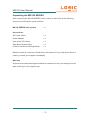
Unpacking the MG150 SERIES
After unpacking the MG150 SERIES carton, check to make sure all the following
items are included and in good condition.
MG150 SERIES main system
x1
Accessories:
AC Power Cable
x1
Power Adapter
x1
User guide CD & driver
x1
Wall Mount Bracket (2pc)
x1
In Wall Front Mount Locking Beads
x1
Make sure that all of the items listed above are present. If any of the above items is
missing, contact your supplier immediately.
Warranty
All products are warranted against defective materials for two year starting from the
date of delivery to the original buyer.
- 3-
MG150 User Manual
Important Safety Precautions
1. Before getting started, read these instructions and save them for later reference.
2. Please disconnect this equipment from any AC outlet before cleaning. Clean with a damp or
dry cloth only. Do not spray any liquid cleaner directly on the screen.
3. The power outlet socket used to plug in the computer power cord must be located near the
system and easily accessible. Do not use outlets on the same circuit of the systems that are
regularly switched on and off.
4. Do not expose the power cord, extension cord and power outlet to moisture or traffic
intensive walkways.
5. Install the equipment on a sturdy and reliable surface to prevent damage caused by
dropping.
6. The openings on the enclosure are for air convection. Protect the equipment from
overheating. DO NOT COVER THE OPENINGS.
7. If the Equipment is sharing an extension cord with other devices, make sure the total ampere
rating of the devices plugged into the extension cord does not exceed the cord’s ampere rating.
8. If an operating system is not installed, an operating system must be loaded first before
installing any software into the equipment.
9. Disconnect the power cord from the computer before any installation of internal components.
Make sure both the computer and the external devices are turned off. A sudden surge of power
may damage sensitive components. Also make sure the computer is properly grounded.
10. During installation of any internal components, be sure to ground yourself to discharge any
static electricity. Most electronic components are highly sensitive to static electric charge. Use a
grounding wrist strap and place all electronic components in any static-shielded devices. If a
wrist-grounding strap is not available, ground your self by briefly touching an unpainted piece of
metal.
11. The brightness of the flat panel display will decrease with use over long periods of time.
However, hours of use will vary depending on the application environment.
12. If the equipment is equipped with a touch panel, avoid using sharp or metallic objects to
operate the touch panel. Scratches on the touch panel may cause mal-calibration or serious
damage to the panel.
13. The LCD panel display is not resistive to shock or vibration. When disassembling the
equipment, make sure the LCD panel is properly and securely installed.
- 4-
MG150 User Manual
CHAPTER 1 - INTRODUCTION
1-6
1.1
General Information
1-6
1.2
Specifications
1-7
CHAPTER 2 - USING THE SYSTEM
2-10
2.1
Identifying the System
2-10
2.1.1
Back Top view
2-10
2.1.2
Back Bottom view
2-10
2.2
First Time System Setup
2-11
2.2.1
Hardware Installation Procedure
2-11
2.2.2
System BIOS Setup
2-11
2.2.3
Operating System and Driver
2-12
2.3
Installation Memory Module
2-12
CHAPTER 3 - TOUCH SCREEN
3-14
3.1
Introduction
3-14
3.2
Specifications
3-14
3.3
Touch Screen Software Driver
3-14
3.4
Touch Screen Care and Clean
3-15
3.5
Troubleshooting
3-15
3.5.1
Display Problems
3-15
3.5.2
Video Alignment Problems
3-15
3.5.3
Software Troubleshooting
3-15
3.5.4
Hardware Troubleshooting
3-16
CHAPTER 4 - INTERFACE
4-17
4.1
External Connector on Main System Box
4-17
4.2
Detach Main System Box from System
4-18
4.3
Install/Upgrade Memory
4-19
4.4
Install/Swap HDD
4-20
4.5
Install Half Slim SSD (For D2550 only)
4-22
4.6
Install 3GS Sim Card (Optional)
4-22
- 5-
MG150 User Manual
4.7
VGA1: VGA CRT Connector: 15 pin D-SUB
4-23
4.8
COM2: RS232/RS422/RS485 9 pin D-SUB
4-23
4.8.1
COM3: RS232 Serial Port Connector: 9 pin D-SUB
4-24
4.9
USB1: USB 2.0/3.0 Port 1,2: USB Type-A
4-24
4.10
LAN1: Gb Ethernet Connector: RD-45 with LED
4-25
4.10.1
LAN2: Gb Ethernet Connector: Standard RD-45 with LED
4-25
- 6-
MG150 User Manual
CHAPTER 1
INTRODUCTION
This chapter includes the MG150 SERIES system background information.
General Information
Specification
Dimensions
1.1 - General Information
The MG150 SERIES is a fanless mini size panel PC with a compact aluminum
chassis as a heat sink, which delivers reliable performance and offers easy
maintenance when service is required.
Featuring Atom Cedar Trail processor, MG150 SERIES combines enhanced digital
media performance with unique thermal solution, and minimizes power consumption
to as little as 24 watts when running at the speed of Dual Core 1.8GHz, bringing up a
quieter and cooler system.
The versatile MG150 SERIES can support one 2.5” HDD drive bay (SATA DOM is
available for option) and DDR3 memory up to 4GB. The myriad of I/O ports located
on the main system box includes two 10/100/1000 Ethernet LAN ports, four USB
ports (2x USB 3.0, 2x USB 2.0), four serial ports for MG150 150/185 (3x RS232, 1x
RS232/422/485), VGA, Audio-In, built-in camera (optional for 12”/15”), built-in RFID
(By Project) and one built-in SATA DOM for flexible expansion capability.
- 7-
MG150 User Manual
1.2 - Specifications
SYSTEM
CPU
6XSSRUW,QWHO$WRP'3URFHVVRUV'XDO&RUH*+]0&DFKH
,QWHO'10([SUHVV&KLSVHW
System Memory
[SLQ9''5,,,62',00VRFNHWWRWDOXSWR*%
Graphics
,QWHO*UDSKLFV0HGLDDFFHOHUDWRU
6XSSRUWGXDOGLVSOD\PLUURULQJPXOWLSOHPRGH
Network
[5HDOWHN57/&%DVH7IDVW(WKHUQHW
J:LUHOHVV/$1PRGXOH2SWLRQDO
%XLOWLQ*60RGXOH2SWLRQDO
Audio
$&&RGHF/LQHLQ/LQHRXW0LF:$032XWSXW
Power Supply
'&9a9:LGH5DQJH,QSXW
OS
:LQGRZV;3;3(9,67$:LQ&(:LQ/LQX[
LED
3RZHU
DISLAY
LCD & Max Resolution
´/('7)7/&'[
´/('7)7/&'[
´/('7)7/&'[
´/('7)7/&'[
Touch Type
ZLUH$QDORJUHVLVWLYH
- 8-
MG150 User Manual
Brightness
´/&'FGPð
´/&'FGP
´/&'FGPð
´/&'FGPð
STORAGE DEVICE
HDD
[´6$7$+''
SATA DOM
*%*%*%+DOI6OLP66'2SWLRQDO
I/O PORTS
USB
MG150 - 08/10/12/15
[86%[86%[86%SRUWV
MG150 - 15
[86%SRUWV[86%;86%SRUWV
MG150 - 12
[86%SRUWV[86%;86%SRUWV
Serial Ports
0*
['%&20
56&20
56&20
6XSSRUWSLQ99VHOHFWLRQE\MXPSHU
LAN
[/$1SRUW*LJDELW/$1
Audio
[/LQHLQ
VGA
['%9*$,QWHUIDFHIRUGXDOGLVSOD\
- 9-
MG150 User Manual
MECHANICAL & ENVIRONMENTAL
Dimension (L x W x H mm)
0*[[
0*[[
0*[[ 0*[[
Weight
0*.*
0*.*
0*.*
0*.*
ENVIRONMENT
EMC & Safety
&()&&
Temperature & Humidity
0*
2SHUDWLQJa&6WRUDJHa&
+XPLGLW\a
Specifications are subject to revision or update without notice
- 10 -
MG150 User Manual
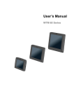
CHAPTER 2
USING THE SYSTEM
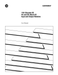
2.1 Identifying the System
2.1.1 - Back Top View
- 11 -
MG150 User Manual
2.2 - First Time System Setup
To set up MG150 Series for the first-time, you should have the following items ready.
These items are either included in the accessory box or available from your local
computer parts store.
0*6HULHV8WLOLW\&',QFOXGHG
3RZHUFRUG,QFOXGHG
36$7RU86%.H\ERDUG1RWLQFOXGHG
36RU86%0RXVH1RWLQFOXGHG
86%&'520'ULYH1RWLQFOXGHG
2SHUDWLQJ6\VWHP26,QVWDOODWLRQ&'1RWLQFOXGHG
2.2.1 - Hardware Installation Procedure
(Prior to turning the power on)
1. Connect a PS/2 keyboard or AT keyboard to the PS/2 keyboard port, or a USB
keyboard to a USB port. If you are using an AT keyboard, you need an adapter (AT to
36.%IRUWKLVFRQQHFWLRQ
2. Connect the PS/2 mouse to the PS/2 mouse port, or a USB mouse to a USB port.
3. Connect the male end of the power cord to an electrical outlet.
4. Connect the USB CD-ROM drive.
5. Connect the female end of the power adapter cord to the AC inlet located at the
rear side of the MG150 Series.
2.2.2 - System BIOS Setup
If you are a commercial user, the MG150 SERIES should have been set up and
configured by your distributor already. In the case where you may find it necessary to
change some system configuration information, you will need to run the Basic Input
Output System (BIOS) setup program. Under the following conditions, the CMOS
settings may be changed:
1. The system is starting and being configured for the first time with new components.
2. The hardware devices attached to the MG150 SERIES system have been
changed.
3. The CMOS memory has lost power and the configuration information has been
erased.
- 12 -
MG150 User Manual
The BIOS setup program is stored in ROM, which can be accessed by pressing
<DEL> key on the keyboard immediately when the system is powered on. In order to
retain the specified setup information when the system power is turned off, the
system setup information is stored in a battery-backed CMOS RAM. The battery is to
ensure the settings will not be erased when the computer is turned off or reset.
When the computer is powered on again, the system will read the settings stored in
the CMOS RAM and compare them to the equipment check conducted during the
power on self-test (POST). If any error or mismatch occurs, an error message will be
shown on the screen and the computer will be prompted to run the setup program.
2.2.3 - Operating System and Driver
The standard MG150 Series system may not be equipped with an operating system
(OS). If you are a commercial user, the system is likely to have been pre-installed
with a proper operating system and software drivers by your dealer or system
integrator. If the system is not pre-installed with any system OS and drivers or you
intend to install your preferred ones, you will need to load an OS and software into
the system.
1. Use the External USB CD-ROM/DVD-ROM Drive to load an OS from a bootable
CD. Recent releases of operating systems include setup programs that load
automatically and guide you through the installation. You can also refer to your OS
user manual for instructions on formatting or partitioning the hard disk drive before
any software installation.
2. Install software drivers for your operating system and any peripherals that are
connected. The MG150 Series Utility CD includes software drivers for Chipset,
Audio, LAN, Touch screen, VGA Display, Camera, 3GS Module and Wireless drivers.
See driver installation chapters for more information.
2.3 - Installation Memory Module
The MG150 Series main board provides one 204-pin SODIMM slot. The socket
supports up to 4GB DDR3. When installing the Memory device, please follow the
steps below:
1. Detach the main system box from the system.
2. Locate the SODIMM slot in the back side of the system box.
- 13 -
MG150 User Manual
3. Unlock a SODIMM slot by pressing the retaining clips outward.
4. Align a SODIMM on the socket such that the notch on the SODIMM matches the
break on the slot.
5. Firmly insert the SODIMM into the slot until the retaining clips snap back in place
and the SODIMM is properly seated.
Available DDR3 configurations refer to the table below for available DDR3
configurations on the mainboard.
Slot
Module Size
Total
SODIMM1
1GB, 2GB, 4GB
1 - 4GB
Maximum Supported System Memory
4GB
- 14 -
MG150 User Manual
CHAPTER 3
TOUCH SCREEN
3.1 - Introduction
The MG150 Series are installed with a 5-wire analog resistive touch screen. The
touch screen panel turns the flat-panel display into a dynamic graphical user
interface (GUI) and data entry device. The touch screen represents a replacement to
needing a keyboard and mouse to interface with the computer. People associate
actions or functions with visual images better than a combination of keystrokes or
button clicks. Using a touch panel is more entertaining for the operator and actually
requires less brain activity than traditional control devices.
The built-in touch screen system has three main components: a clear solid glass
screen formed to match the shape of a display, a sophisticated electronic controller,
and a software driver.
3.2 - Specifications
MG150 Series supports HIGGSTEC touch panel. Please check specifications as
following.
Input Method
Finger, gloved hand, or touch stylus.
Optical Transmittance
Operating Force
Stylus=R0.8,
Environmental/Relative
Humidity
2SHUDWLQJ&WR&a5+
6WRUDJH&WR&a5+
Constant Temperature/
Humidity
&5+KUV
allow panel stays in normal environment for 4 hrs
Surface Durability +SHQFLOSUHVVXUH1
Durability
50g
.QRFN7HVWWLPHV
3.3 - Touch Screen Software Driver
Touch screens configured with the MG150 Series will require software drivers to be
installed to enable the touch screen functionality. The driver software scales the
- 15 -
MG150 User Manual
absolute coordinates received from the touch screen controller into translated screen
coordinates, using the calibration points obtained with the Video Alignment program
included with the driver software. The driver also performs other operations as
directed by the application.
3.4 - Touch Screen Care and Clean
2QO\XVHVRIWQRQDEUDVLYHOLQWIUHHZLSHVZLWK,VRSURS\OWRFOHDQGLUWRUVWDLQV
found on the touch panel. Always dampen the wipes and then clean the touch panel.
Chemical liquids with strong acidic base will damage the touch screen and void the
warranty.
3.5 - Troubleshooting
If you experience operational difficulties with the touch screen system either during
or after installation, the following sections will help you to determine the source of
problems.
The first step in troubleshooting is to determine whether the problem is related to the
display, software, or hardware. And please pay attention to special notes as follows.
'RQRWFRQIXVHGLVSOD\SUREOHPVZLWKWRXFKVFUHHQSUREOHPVDVWKHWZRLVVXHVDUH
unrelated.
6RIWZDUHSUREOHPVDUHGHWHUPLQHGE\DEDVLFKDUGZDUHIXQFWLRQDOLW\WHVW,IWKH
hardware transmits touch coordinates correctly, then the problem is probably with the
driver or application software.
+DUGZDUHSUREOHPVPD\EHFDXVHGE\WKHWRXFKVFUHHQFRQWUROOHUFDEOLQJSRZHU
supply, or the integration of the touch screen components in the display.
3.5.1 - Display Problems
If the display has some problems (such as no video, no horizontal or vertical
synchronization, raster non-linearity, etc.), remember that the video function of the
display and the touch screen installed on the display are separated systems.
Therefore, problems with the display should be treated as display problems, not
touch screen problems. Diagnostic procedures and any possible corrections for
display problems should be performed.
- 16 -
MG150 User Manual
3.5.2 - Touch Alignment Problems
If the touch screen is responding and the data is linear, but it does not respond at the
appropriate zone, try to align the Touch. Use Touchkit program.
3.5.3 - Software Troubleshooting
Before beginning software troubleshooting, verify that the touch screen hardware is
working normal for serial controllers by running the touchscreen program. If the
touch screen is operating, then the problem may be with the driver software, the
application software, or a conflict with other hardware or software. (The problem may
also be due to incorrect Video Alignment of touch screen).
3.5.4 - Hardware Troubleshooting
The touch screen system hardware troubleshooting may require analysis of the
touch screen, controller, cables, power supply, and the integration process. To start
with the controller would be the best. Use the controller power-on diagnostics that
are displayed when the touch panel utility driver software is loaded to check for
specific faults. Also check whether the controller is transmitting any touch data.
No touch data:
When no touch data is reported, the problem may be the touch screen, controller, or
cabling. If the features of controller power-on or LED do not identify the problem, you
can use individual system components what are available to be instead.
Intermittent touch data:
If the system is reporting touch data at a slow or varying rate, the problem may be
caused by a low signal strength or excessive noise in the system. And when the
touch screen is not touched but it shows the touch data often caused by excessive
system noise.
- 17 -
MG150 User Manual
CHAPTER 4
INTERFACE
This chapter describes the design features of the system.
4.1 - External Connector on Main System Box
Mouse and Keyboard
86%0RXVHDQG.H\ERDUGDUHWREHXVHGXQOHVV36SRUWVDUHVSHFLILFDOO\
requested for project use.
Serial Port
The serial port is a 16550a high speed communications port that sends/receives 16
bytes FIFOs. You can attach a serial mouse or other serial devices directly to the
connector.
VGA Port
The DB15-pin female connector is connecting to LCD panel.
USB Ports
USB ports are for attaching USB devices such as keyboard, mouse, or other
USB-compatible device.
LAN
The standard RJ-45 LAN jack is for connection to Local Area Network. You can
connect a network cable to it.
Audio Ports
Line In is used for external CD player, or other audio devices. Rear-Surround Out in
4/5.1/7.1 channel mode. Line out, is a connector for speakers or headphones. Mic, is
a connector for microphones. Center/Subwoofer Out in 5.1/7.1 channel
- 18 -
MG150 User Manual
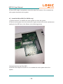
4.2 - Detach Main System Box from System
1) Flip the System to the back and have the system box face towards you.
2) Remove L and R screw in the side of the system box like shown in the following
picture.
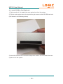
3) Once the locking screws are removed, pull the main system box downwards until
the connector is separated like the following picture.
- 19 -
MG150 User Manual
4) Then pick up the system box and ensure the alignment screws are free from the
side brackets like shown in the following pictures.
5) To replace and reinstall the Main system box, please reverse the above steps.
4.3 - Install/Upgrade Memory
1) Follow the steps from section 4.2 to remove the main system box.
2) Once removed, flip the main system box to have the back side facing towards you
to access the quick maintenance opening for the memory module. (Like shown in the
following picture.)
- 20 -
MG150 User Manual
3) Unlock a SODIMM slot by pressing the retaining clips outward.
4) Align a SODIMM on the socket such that the notch on the SODIMM matches the
break on the slot.
5) Firmly insert the SODIMM into the slot until the retaining clips snap back in place
and the SODIMM is properly seated.
6) Reverse the steps from section 4.2 to re-attach the main system box to the
system.
4.4 Install/Swap HDD
1) Follow the steps from section 4.2 to remove the main system box.
2) Once removed, flip the main system box to have the back side facing towards you
to access the quick maintenance HDD on the left top corner.
3) Remove the HDD bottom screw completely like shown in the following picture.
- 21 -
MG150 User Manual
4) Slightly Loosen the HDD top locking screw completely like shown in the following
picture.
5) Push outward on the top locking screw that was loosened in step 4 to remove
HDD. (Like shown in the following pictures.)
- 22 -
MG150 User Manual
6) Once HDD swap is completed, reverse the step from section 4.2 to re-attach the
main system box back to the system.
4.5 - Install Half Slim SSD (For D2550 only)
1) Follow section 4.2 to detach the main system box from the system.
2) Flip the main system box to the back side to gain access to the quick maintenance
opening for the SSD slot. (Like Shown in the following picture)
3) Swap/Install the Half Slim SSD.
4) Reverse the steps from section 4.2 to re-attach the main system box to the
system.
- 23 -
MG150 User Manual
4.6 - Install 3GS Sim Card (Optional)
1) Follow section 4.2 to detach the main system box from the system.
2) Flip the main system box to the top side to gain access to the 3GS SIM card slot.
(Like shown in the following picture)
3) Insert the SIM card and reverse the steps from section 4.2 to re-attach the main
system box to the system.
- 24 -
MG150 User Manual
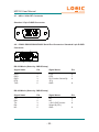
4.7 - VGA1: VGA CRT Connector
Standard 15 pin D-SUB Connector
4.8 - COM2: RS232/RS422/RS485 Serial Port Connector: Standard 9 pin D-SUB
Connector
5
1
6
9
RS-232 Mode (Select by CMOS Setup)
Signal Name
Pin
Signal Name
Pin
DCD
DSR
5;'
RTS
7;'
1
2
3
4
5
CTS
DTR
RI (Function Select By
JP1)
GND
6
7
8
9
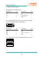
RS-422 Mode (Select by CMOS Setup)
Signal Name
Pin
Signal Name
Pin
7;
5;
7;
5;
NC
1
2
3
4
5
NC
NC
99)XQFWLRQ
Select By JP1)
GND
6
7
8
- 25 -
9
MG150 User Manual
4.7 - VGA1: VGA CRT Connector
RS-485 Mode (Select by CMOS Setup)
Signal Name
Pin
Signal Name
Pin
57;
1
2
3
4
5
NC
NC
99)XQFWLRQ
Select By JP1)
GND
6
7
8
57;
NC
9
4.8.1 - COM3: RS232 Serial Port Connector: Standard 9 pin D-SUB
ConnectorRS-485 Mode (Select by CMOS Setup)
5
1
6
9
Signal Name
Pin
Signal Name
Pin
DCD
DSR
5;'
RTS
7;'
1
2
3
4
5
CTS
DTR
RI (Function Select By
JP1)
GND
6
7
8
9
4.8.1 - USB1: USB 2.0/3.0 Port 1,2: Standard USB Type-A Connector
- 26 -
MG150 User Manual
4.8.1 - LAN1: Giga bit Ethernet Connector: Standard RD-45 with LED
LED
Signal Name
Yellow
Green
Orange
Link & Active
10/100M LAN Speed
Giga LAN Speed
4.10.1 - LAN2: Giga bit Ethernet Connector: Standard RD-45 with LED
LED
Signal Name
Yellow
Green
Orange
Link & Active
10/100M LAN Speed
Giga LAN Speed
- 27 -