1
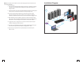
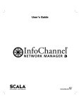
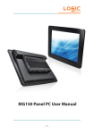
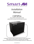
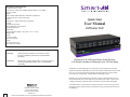
TECHNICAL SPECIFICATIONS Connector HD-15 socket Format VGA, SVGA, XGA, RGBHV, RGsB, CVBS, YC, YUV, RGBS Syncs TTL5VDC Audio Signal 15kHz 0db unbalanced 100 Ohms impedance Connector RCA or 3.5mm stereo jack Power Voltage 90 – 230V, 5VDC 3A A/S 50/60Hz Control IR Optional IR control TCP/IP Optional TCP/IP control RS-232 RS-232 jacks Dimensions Height x Width x Depth 1.5U (5.24” x 19” x 11.25”) Weight 20lb Video In HD-15 female Out HD-15 female Audio In 3.5mm stereo jack Out 3.5mm stereo jack Quick Start User Manual AVRouter 8x8 ORDERING INFORMATION AV08X08S Routes 8 UXGA/component to 8 remote monitors Includes: [AV08X08, (PS5VDC 3A),CCRS23205MM, (SM-CSW)] AV08X08AS UXGA/audio routes 8 UXGA/audio to 8 remote monitors Includes: [AV08X08A, (PS5VDC 3A), CCRS23205MM (SM-CSW)] Routes up to 8 XVGA and Stereo Audio Sources to 8 Remote Location at Distances up to 100 feet Away SmartAVI’s AV Router 8x8 gives you the power to pull content from up to 8 separate computers and display it on up to 8 monitors individually or at the same time. As you will soon find, this dynamic hardware/software solution makes even the most “complicated” content delivery challenge a snap. Whether you’ve purchased the A/V 8x8 for a retail, recording studio or even mass-transit location, we encourage you to broaden your vision – explore your creativity and use this dynamic piece of hardware to your fullest advantage. 2840 N. Naomi Ave. Burbank, California 91504 Phone: (818) 565-0011 Facsimile: (818) 565-0020 smartavi.com 7 Please visit smartavi.com for a expanded version of this manual. This matrix switch is a powerful tool that you will now use to convey your own message to clients, guests and/or employees the way you need it and want it to be displayed. Getting Started Hardware Installation &RQQHFWDVHULDOFDEOHIURPWKH$95RXWHU[WRWKHFRQWURO FRPSXWHU,I\RXKDYHLQVWDOOHGWKH&'520RQDODSWRS\RXFDQ XVHDVHULDOWR86%DGDSWHUWRPDNHWKLVFRQQHFWLRQ &RQQHFWXSWRFRPSXWHUVFRQWDLQLQJ\RXUYLGHRFRQWHQWWRWKH ´YLGHRLQµSRUWVRIWKH$95RXWHU[XVLQJ'9,PDOHH[WHQVLRQ FDEOHVVDPHIRUWKHDXGLRFDEOHVXVLQJPPVWHUHRMDFN &RQQHFWXSWRGLVSOD\PRQLWRUVWRWKH´YLGHRRXWµSRUWVRIWKH $95RXWHU[XVLQJ;9*$,PDOHH[WHQVLRQFDEOHV 3OXJLQWKHSRZHUFRUGWRWKH$95RXWHU[DQGWXUQWKHGHYLFH RQ 7XUQRQDOOFRPSXWHUVDQGPRQLWRUVEHLQJXVHG Features (QULFKHVFRQWHQWSDOHWWHZLWKWKHFDSDELOLW\RIEHLQJDEOHWRSXOOYLGHR LPDJHVHWFIURPXSWRVHSDUDWH&38VWRGLVSOD\RQRQHWR PRQLWRUVLQGLYLGXDOO\RUDWWKHVDPHWLPH [QRQEORFNLQJVLQJOHOLQN9*$$8',2PDWUL[VZLWFKWKDWVXSSRUWV +'79UHVROXWLRQVXSWR[ &RQWUROYLDIURQWSDQHO/&'GLVSOD\56RYHUWKH,QWHUQHW7&3,3 'LVSOD\KLJKGHILQLWLRQFRQWHQWXSWRIHHWDZD\IURPWKH&38V ZLWKRXWWKHXVHRIDGGLWLRQDOH[WHQVLRQKDUGZDUH Controlling the A/VRouter 8x8 7KHUHDUHPXOWLSOHZD\VWRFRQWUROWKH'9,5RXWHU[<RXFDQRSHUDWHWKH URXWHUYLD )URQW3DQHO/&''LVSOD\,QSXW 56TXHULHV 6PDUW$9,·V:LQGRZV%DVHG6RIWZDUH,QFOXGHGRQ&'520 1RWH,I\RXXVH0DFUDWKHUWKDQ3&RUGRQRWZLVKWRLQVWDOOWKH&'520 VRIWZDUHWKH$95RXWHU[KDUGZDUHFDQEHSURJUDPPHGDQGFRQWUROOHG ZLWKRXWLW 2SWLRQDO,5RU7&3,3,QWHUQHW&RQWURO3RVVLEOH8VLQJ6PDUW$9,·V 607&3'HYLFH Input/Output Control %\XVLQJWKH,QSXW2XWSXW6HOHFWEXWWRQVRQWKHIURQWSDQHORIWKH$95RXWHU [\RXFDQVHOHFWZKLFKLQSXWSRUWJRHVWRZKLFKRXWSXWSRUWVRIWKHGHYLFH 7KLVZLOOKDYH\RXUGLJLWDOVLJQDJHXSDQGUXQQLQJTXLFNO\DQGHDVLO\,IWKH URXWHULVSRZHUHGRII\RXZLOOQHHGWRPDQXDOO\VHWXSWKHLQSXWRXWSXW VHWWLQJVDJDLQWR\RXUVSHFLILFDWLRQV Practical Applications 5HWDLO'HDOHUVKLS/RFDWLRQV 5HVWDXUDQW/RXQJH'LJLWDO6LJQDJH 0DVV7UDQVLW6WDWLRQV +RWHO5HVRUW&DVLQR,QIRUPDWLRQ 0RYLH7KHDWHUV 7KHPH3DUNV 5HFRUGLQJ6WXGLRV %RDUG0HHWLQJ5RRPV (GXFDWLRQDO&DPSXVHV Whats included 1 6 Macros: This section of the window is used to save and play back macros. Macros store a set sequence of routes. To record a macro: 1. . Click on the Record button (last button shown above). A blinking “recording” message below this button will be displayed to indicate that all routes are being recorded. 2. . Select the desired cross points. (See Matrix Routing for details on making these routes.) There is no limit on the number of routes you may record. Installation Diagram PC 8 Internet PC 3 PC 2 PC 1 3. If you click a macro button while in the record mode, the macro will be executed, and these routes will be added to the recording. This makes it possible to combine the routes of two or more macros into one bigger macro. Monitor 1 Monitor 2 4. When finished, click the “Save Macro” button. You will be instructed to then click on one of the macro buttons. Doing this will save the recorded routes to that button. To cancel saving the macro, click the “Cancel Save” button. 5. To play back a macro, simply click on one of the 50 macro buttons. Use the scrollbar to bring any of these into view. Monitor 8 AV Router 8x8 SMTCP 6. The macros are automatically saved in the current configuration file. They are also saved when you select the File/Save Configuration... menu. Laptop (Control) To save macros in a separate file for a special purpose, select the File/Save Macros...menu. 5 2 Software Installation & Operation Inputs/Outputs: Enter the number of Inputs/Outputs your AVRouter has. For now we will assume that there are 16 inputs and 16 outputs. The Main Routing Window enables you to control the router(s) connections by means of the matrix panel, the button panel, or with pre-recorded routes called macros. Com Port: Select the appropriate com port that your computer is using to access the router. Matrix Panel: This is probably the simplest way to route the connections. Simply click on the cross point itself. The input on the left will then be routed to the output above. Router Timeout: By default this is 0 meaning the computer acknowledges commands almost instantly. Sometimes a computer takes longer to respond. This setting should be left at 0. If you need to change it, it should be no higher than 0.2. Note: Inputs can be routed to several different outputs, but each output can only have a single input at any one time. So you can have several connections horizontally but not vertically. After you have entered in the necessary information click OK. This will now take you to the Main Routing Window where you can route the different video/audio connections. The Button Panel: These are the numbered buttons across the top and left sides. Click an output button on the top, and then click an input button on the left. On this screen you will notice the input buttons running down the left side while the output buttons run across the top. They are each labeled 1 through 16. Note: The three small colored buttons at the lower right labeled ALL, VIDEO, and AUDIO are not available if AV Split was not checked when you configured your router. Options for using the Button Panel Output Options: To select multiple outputs next to each other, click on one output, then hold the shift key down and click the last output. When the input is clicked, it is routed to all selected outputs To select multiple outputs individually, hold the control key down and click on any number of outputs. When the input is clicked, it is routed to all selected outputs. Input Options: To route an input to all the outputs at once, hold the control key down and click on an input. To leave the outputs selected after the route is made, hold the shift key down and click on an input. 3 4