1
Computer Engineering
2009
Mekelweg 4,
2628 CD Delft
The Netherlands
http://ce.et.tudelft.nl/
MSc THESIS
Reliable Ground Segment Data Handling System
for Delfi-n3Xt Satellite Mission
Dwi Hartanto
Abstract
Delfi-n3Xt, the successor of Delfi-C3 , is currently under development at Delft University of Technology and scheduled for lunch
in the summer of 2010. The satellite belongs to the nanosatellite
class, which means that it has mass between one and ten kilograms.
This improved nanosatellite platform of (10 x 10 x 34) cm3 and 3.5
kg allows novel technology demonstration and qualification for future small satellites and innovative scientific research in space. The
new platform is a significant improvement (compared to Delfi-C3 ) by
implementing a high-speed downlink, three-axis stabilization and a
CE-MS-2009-14
single-point-of-failure free implementation of batteries in the electrical power subsystem (EPS). Delfi-n3Xt satellite makes use of global
network of radio amateurs and their Internet connection for receiving
and gathering the continuous data telemetry in a central database.
Learning from previous system experience applied in the Delfi-C3 ,
there were many flaws in the data-handling system of the ground
segment due to a very late system development. Delfi-n3Xt will
make use of low speed continuous telemetry downlink and high speed
downlink for passes over the Delft Central Ground Segment (DCGS).
The low speed link is very robust and proven system, however since
there is no global or full time coverage of radio amateurs, there will
be many gaps in the gathered data. The high speed downlink will send down all measurements onboard
the satellite, however because this component is a new system, it will be less reliable due to dependency
on the attitude control of the satellite. The main objective of this thesis is to develop a reliable ground
segment data handling system for Delfi-n3Xt satellite mission. In order to accomplish this objective, several steps were conducted sequentially: (1) analyze the Delfi-C3 problems with the ground segment data
handling system, (2) design the data-handling system for Delfi-n3Xt satellite mission which is less prone to
irreversible human error, (3) develop ground segment telemetry downlink decoder software for Delfi-n3Xt
satellite mission, (4) build proof-of-concept for the data handling system using Delfi-C3 data and Delfi-n3Xt
simulation, and (5) evaluate reliability, flexibility and performance of the software system. As a result, novel
data handling system for Delfi-n3Xt satellite which is more secure, flexible and reliable is introduced and
ready to use for the mission in 2010.
Faculty of Electrical Engineering, Mathematics and Computer Science
Reliable Ground Segment Data Handling System
for Delfi-n3Xt Satellite Mission
THESIS
submitted in partial fulfillment of the
requirements for the degree of
MASTER OF SCIENCE
in
COMPUTER ENGINEERING
by
Dwi Hartanto
born in Madiun, Indonesia
Computer Engineering
Department of Electrical Engineering
Faculty of Electrical Engineering, Mathematics and Computer Science
Delft University of Technology
Reliable Ground Segment Data Handling System
for Delfi-n3Xt Satellite Mission
by Dwi Hartanto
Abstract
elfi-n3Xt, the successor of Delfi-C3 , is currently under development at Delft University of
Technology and scheduled for lunch in the summer of 2010. This improved nanosatellite
platform allows novel technology demonstration and qualification for future small satellites and innovative scientific research in space. The new platform is a significant improvement
by implementing a high-speed downlink, three-axis stabilization and a single-point-of-failure free
implementation of batteries in the electrical power subsystem (EPS). Delfi-n3Xt satellite makes
use of global network of radio amateurs and their Internet connection for receiving and gathering
the continuous data telemetry in a central database. Learning from previous system experience
applied in the Delfi-C3 , there were many flaws in the data-handling system of the ground segment due to a very late system development. Delfi-n3Xt will make use of low speed continuous
telemetry downlink and high speed downlink for passes over the Delft Central Ground Segment
(DCGS). The low speed link is very robust and proven system, however since there is no global
or full time coverage of radio amateurs, there will be many gaps in the gathered data. The high
speed downlink will send down all measurements onboard the satellite, however because this
component is a new system, it will be less reliable due to dependency on the attitude control
of the satellite. The main objective of this thesis is to develop a reliable ground segment data
handling system for Delfi-n3Xt satellite mission. In order to accomplish this objective, several
steps were conducted sequentially: (1) analyze the Delfi-C3 problems with the ground segment
data handling system, (2) design the data-handling system for Delfi-n3Xt satellite mission which
is less prone to irreversible human error, (3) develop ground segment telemetry downlink decoder
software for Delfi-n3Xt satellite mission, (4) build proof-of-concept for the data handling system
using Delfi-C3 data and Delfi-n3Xt simulation, and (5) evaluate reliability, flexibility and performance of the software system. As a result, novel data handling system for Delfi-n3Xt satellite
which is more secure, flexible and reliable is introduced and ready to use for the mission in 2010.
D
Laboratory
Codenumber
:
:
Committee Members
:
Computer Engineering
CE-MS-2009-14
Advisor:
Dr. ir. Georgi Gaydadjiev, CE, TU Delft
Chairperson:
Dr. ir. Koen Bertels, CE, TU Delft
Member:
Dr. ir. Zaid Al-Ars, CE, TU Delft
Member:
Dr. ir. Jaap Hoekstra, Elca, TU Delft
i
ii
to my beloved family (The Hartantos)
iii
iv
Contents
List of Figures
viii
List of Tables
ix
Acknowledgements
xi
1 Introduction
1.1 Delfi-n3Xt Mission Objective . . . . . . . . . . . . . . . . . . . . . . .
1.2 Delfi-n3Xt Payloads . . . . . . . . . . . . . . . . . . . . . . . . . . . .
1.2.1 Cool Gas Micropropulsion system - TNO, TU Delft, UTwente .
1.2.2 Multifunctional Particle Spectrometer (MPS) - Cosine Research
1.2.3 Space Flash Memory - NLR . . . . . . . . . . . . . . . . . . . .
1.2.4 Hydrogenated Amorphous Silicon Solar Cells - DIMES . . . . .
1.2.5 Efficient Nanosatellite Transceiver Module - ISIS BV . . . . . .
1.3 Delfi-n3Xt Subsystem . . . . . . . . . . . . . . . . . . . . . . . . . . .
1.3.1 Electrical Power Subsystem (EPS) . . . . . . . . . . . . . . . .
1.3.2 Command and Data Handling System (CDHS) . . . . . . . . .
1.3.3 Communication System (COMMS) . . . . . . . . . . . . . . . .
1.3.4 Attitude Determination and Control Subsystem (ADCS) . . . .
1.3.5 Structural Subsystem (STS) . . . . . . . . . . . . . . . . . . . .
1.3.6 Thermal Control Subsystem (TCS) . . . . . . . . . . . . . . . .
1.4 Thesis Objective . . . . . . . . . . . . . . . . . . . . . . . . . . . . . .
1.5 Thesis Organization . . . . . . . . . . . . . . . . . . . . . . . . . . . .
1
. . 1
. . 2
. . 2
BV 2
. . 4
. . 4
. . 4
. . 6
. . 6
. . 6
. . 6
. . 8
. . 8
. . 9
. . 9
. . 12
2 Satellite Telecommunication System
2.1 General Satellite Telecommunication System
2.2 Satellite Communication links . . . . . . . . .
2.2.1 Satellite Communication Protocols . .
2.3 Delfi-n3Xt Communication System . . . . . .
2.3.1 Delfi-n3Xt Space Segment . . . . . . .
2.3.2 Delfi-n3Xt Ground Segment . . . . . .
.
.
.
.
.
.
.
.
.
.
.
.
.
.
.
.
.
.
.
.
.
.
.
.
.
.
.
.
.
.
.
.
.
.
.
.
.
.
.
.
.
.
.
.
.
.
.
.
.
.
.
.
.
.
.
.
.
.
.
.
.
.
.
.
.
.
.
.
.
.
.
.
.
.
.
.
.
.
.
.
.
.
.
.
.
.
.
.
.
.
.
.
.
.
.
.
13
13
14
16
17
19
21
3 Delfi-C3 Ground Segment
3.1 Overview of Delfi-C3 Ground Segment . . . .
3.1.1 Delft Command Ground Station . . .
3.1.2 Eindhoven Command Ground Station
3.1.3 Worldwide Radio Amateur Network .
3.2 Delfi-C3 Ground Segment Software . . . . . .
3.2.1 Satellite Tracker (Orbitron) . . . . . .
.
.
.
.
.
.
.
.
.
.
.
.
.
.
.
.
.
.
.
.
.
.
.
.
.
.
.
.
.
.
.
.
.
.
.
.
.
.
.
.
.
.
.
.
.
.
.
.
.
.
.
.
.
.
.
.
.
.
.
.
.
.
.
.
.
.
.
.
.
.
.
.
.
.
.
.
.
.
.
.
.
.
.
.
.
.
.
.
.
.
.
.
.
.
.
.
23
23
23
27
29
30
30
v
3.2.2
3.3
3.4
RASCAL (Radio Amateur Satellite Communications Autonomous
Logger) . . . . . . . . . . . . . . . . . . . . . . . . . . . . . . . . .
Delfi-C3 Ground Segment Technical Problem (RASCAL) . . . . . . . . . .
3.3.1 Overview of RASCAL . . . . . . . . . . . . . . . . . . . . . . . . .
3.3.2 RASCAL’s Software/Code Investigation . . . . . . . . . . . . . . .
3.3.3 Result of RASCAL Investigation . . . . . . . . . . . . . . . . . . .
Lesson Learned . . . . . . . . . . . . . . . . . . . . . . . . . . . . . . . . .
4 Design of Delfi-n3Xt Ground Segment (DUDe)
4.1 Delfi-n3Xt Ground Segment Design . . . . . . . . . . . . . . . . . . .
4.1.1 Delft Command Ground Station (DCGS) . . . . . . . . . . .
4.1.2 World Wide Radio Amateur Network . . . . . . . . . . . . .
4.1.3 GENSO (Global Educational Network of Satellite Operation)
4.2 DUDe (Delfi Universal Data Extractor) . . . . . . . . . . . . . . . .
4.2.1 Delfi-n3Xt Satellite Data Telemetry (Data Budget) . . . . . .
4.2.2 DUDe System Telemetry Design . . . . . . . . . . . . . . . .
5 Implementation and Evaluation
5.1 DUDe System Development . . . . . . . . . . . .
5.1.1 Commercial-of-the-Shelf (COTS) Software
5.2 DUDe’s GUI Class Diagram and Architecture . .
5.2.1 Graphical User Interface . . . . . . . . . .
5.2.2 Detail DUDe Class Implementation . . . .
5.2.3 DUDe Protocol Definition . . . . . . . . .
5.3 DUDe Performance and Reliability Evaluation .
.
.
.
.
.
.
.
.
.
.
.
.
.
.
.
.
.
.
.
.
.
. . . . . . . . . . . . . .
Development Technology
. . . . . . . . . . . . . .
. . . . . . . . . . . . . .
. . . . . . . . . . . . . .
. . . . . . . . . . . . . .
. . . . . . . . . . . . . .
30
30
33
33
35
40
43
43
43
43
45
45
47
52
67
67
67
67
67
72
74
79
6 Conclusions and Future Work
93
Bibliography
97
vi
List of Figures
1.1
1.2
1.3
1.4
1.5
1.6
1.7
2.1
Engineering model (A) and a computer model (B) showing the cool gas
generator micropropulsion system [3] . . . . . . . . . . . . . . . . . . . . . 3
3D Drawing of MPS [3] . . . . . . . . . . . . . . . . . . . . . . . . . . . . 5
EPS architecture [3] . . . . . . . . . . . . . . . . . . . . . . . . . . . . . . 7
Functional breakdown of the CHDS [3] . . . . . . . . . . . . . . . . . . . . 7
Overview of Delfi-n3Xt Communication subsystem [3] . . . . . . . . . . . 8
Delfi-n3Xt structure rendering breakdown [3] . . . . . . . . . . . . . . . . 9
(a) General input-output system and (b) Conceptual Delfi-n3Xt thermal
system [3] . . . . . . . . . . . . . . . . . . . . . . . . . . . . . . . . . . . . 10
2.2
2.3
2.4
2.5
2.6
Telecommunications via satellite in the telecommunications infrastructure
[8] . . . . . . . . . . . . . . . . . . . . . . . . . . . . . . . . . . . . . . . .
General concept of satellite communication system [6] . . . . . . . . . . .
General layout of top level RF link satellite communication system [16] .
Overview of Delfi-n3Xt communication system [17] . . . . . . . . . . . . .
The linear transponder block design [17] . . . . . . . . . . . . . . . . . . .
Operations of the communication system [17] . . . . . . . . . . . . . . . .
14
15
16
18
20
22
3.1
3.2
3.3
3.4
3.5
3.6
3.7
3.8
3.9
3.10
Delfi-C3 ground segment system break down [37] . . . . .
Delfi-C3 ground segment communication architecture [16]
Block diagram of system operations at Delft-CGS [19] . .
Delfi-C3 command ground station equipment [37] . . . . .
Data processing in DCGS [38] . . . . . . . . . . . . . . . .
Orbitron main screen (tracking Delfi-C3 ) . . . . . . . . . .
RASCAL main screen [22] . . . . . . . . . . . . . . . . . .
Ground Station Network data flow [39] . . . . . . . . . . .
RASCAL data processing flow algorithm [35] . . . . . . .
RASCAL class diagram overview [22] . . . . . . . . . . . .
.
.
.
.
.
.
.
.
.
.
.
.
.
.
.
.
.
.
.
.
.
.
.
.
.
.
.
.
.
.
.
.
.
.
.
.
.
.
.
.
.
.
.
.
.
.
.
.
.
.
.
.
.
.
.
.
.
.
.
.
.
.
.
.
.
.
.
.
.
.
.
.
.
.
.
.
.
.
.
.
.
.
.
.
.
.
.
.
.
.
24
25
26
28
29
31
32
34
36
37
4.1
4.2
4.3
4.4
4.5
4.6
4.7
4.8
4.9
Delfi-n3Xt ground segment top level design overview
GENSO world participation’s map [29] . . . . . . . .
GENSO communication architecture [30] . . . . . . .
DUDe data processing algorithm [35] . . . . . . . . .
DUDe front-end system . . . . . . . . . . . . . . . .
DUDe main/ core system design . . . . . . . . . . .
Three-way handshake communication concept [15] .
NTP architecture [32] . . . . . . . . . . . . . . . . .
DUDe data processing flowchart . . . . . . . . . . .
.
.
.
.
.
.
.
.
.
.
.
.
.
.
.
.
.
.
.
.
.
.
.
.
.
.
.
.
.
.
.
.
.
.
.
.
.
.
.
.
.
.
.
.
.
.
.
.
.
.
.
.
.
.
.
.
.
.
.
.
.
.
.
.
.
.
.
.
.
.
.
.
.
.
.
.
.
.
.
.
.
44
46
47
53
55
57
62
64
65
5.1
5.2
5.3
5.4
DUDe main screen while performs decoding Delfi-C3 telemetry
Distributed object using RMI concept [33] . . . . . . . . . . . .
FX.25 basic structure [13] . . . . . . . . . . . . . . . . . . . . .
D-Start protocol configuration [9] . . . . . . . . . . . . . . . . .
.
.
.
.
.
.
.
.
.
.
.
.
.
.
.
.
.
.
.
.
.
.
.
.
68
73
76
78
vii
.
.
.
.
.
.
.
.
.
.
.
.
.
.
.
.
.
.
.
.
.
.
.
.
.
.
.
5.5
5.6
5.7
5.8
5.9
5.10
5.11
5.12
5.13
5.14
5.15
5.16
SEEDS protocol configuration (part a) [12] . . . . .
SEEDS protocol configuration (part b) [12] . . . . .
SEEDS protocol configuration (part c) [12] . . . . .
SEEDS protocol configuration (part d) [12] . . . . .
PRISM protocol configuration [34] . . . . . . . . . .
SSP protocol configuration [26] . . . . . . . . . . . .
DUDe setup testing . . . . . . . . . . . . . . . . . .
DUDe in the testing phase using Delfi-C3 telemetry
DUDe in the testing phase using CANX-5 telemetry
DUDe in the testing phase using SEEDS telemetry .
Raw DataFrame from DCGS server (simulation) . .
Raw DataFrame from DUDe logging system . . . . .
viii
.
.
.
.
.
.
.
.
.
.
.
.
.
.
.
.
.
.
.
.
.
.
.
.
.
.
.
.
.
.
.
.
.
.
.
.
.
.
.
.
.
.
.
.
.
.
.
.
.
.
.
.
.
.
.
.
.
.
.
.
.
.
.
.
.
.
.
.
.
.
.
.
.
.
.
.
.
.
.
.
.
.
.
.
.
.
.
.
.
.
.
.
.
.
.
.
.
.
.
.
.
.
.
.
.
.
.
.
.
.
.
.
.
.
.
.
.
.
.
.
.
.
.
.
.
.
.
.
.
.
.
.
.
.
.
.
.
.
.
.
.
.
.
.
80
81
82
83
84
85
86
87
88
90
91
92
List of Tables
4.1
Payload data packages with sizes and preferred sampling rate [10] . . . . . 51
5.1
5.2
FEC Algorithms and Correlation Tag Value Assignments [13] . . . . . . . 77
Layout of AX.25 UI Frame . . . . . . . . . . . . . . . . . . . . . . . . . . 77
ix
x
Acknowledgements
I am grateful for all the help and support I received during my thesis project. Therefore,
my thanks go out to my advisors, Georgi Gaydadjiev, for all his advice, great support,
and encouragement, to Jasper Bouwmeester who lured me into the Delfi-n3Xt project
and introducing me to the world of space technology. Thank you Martijn de Milliano and
Sybren de Jong for guiding and helping me in the first stage of Delfi-n3Xt project, answering a lot of questions and introducing me to the world of radio amateurs. My thanks
go to Arthur Tindemans, Mattias Genbrugge, Christiane Muller, Christina Corvaglia,
Lisero Perez, Jennifer Go, Napoleon Cornejo, Armin Noroozi and the entire Delfi-n3Xt
team for the good teamwork, for the enthusiasm they shared designing a satellite together
and for having a lot of fun.
Also, I would like to take the opportunity to thank the people that have played an
important role in my life. First of all my parents and my brother and his family, thank
you for your nurturing, support, love, confidence and thought of me in your prayers over
the years! Many thanks to Depkominfo family that make my dreams come true. Finally,
I would like to acknowledge the support of all CE members, my master fellow students
and my ”Delft-Indonesian” family who have been there for me and shares a lot of great
time together. Matur nuwun!
NB. Some parts of this thesis work contain information taken from the technical
documentation of Delfi-n3Xt project.
Dwi Hartanto
Delft, The Netherlands
July 1, 2009
xi
xii
1
Introduction
Delfi-n3Xt, the successor of Delfi-C3 , is currently under development at Delft University of Technology and scheduled for lunch in the summer 2010. The satellite is of the
nanosatellite class, which means that it has mass between one and ten kilograms. This
improved nanosatellite platform of (10 × 10 × 34) cm3 and 3.5 kg allows novel technology demonstration and qualification for future small satellites and innovative scientific
research. The platform is improved (compared to Delfi-C3 ) by implementing a highspeed downlink, three-axis stabilization and a single-point-of-failure free implementation
of batteries in the electrical power subsystem (EPS). This chapter present the details
of Delfi-n3Xt satellite preliminary design and mission overview, which the information
on subchapter 1.1 − 1.3 taken from project´’s technical documentation [3], followed by
the thesis objectives; development of reliable ground segment data handling system for
Delfi-n3Xt satellite mission.
1.1
Delfi-n3Xt Mission Objective
Delfi-n3Xt Nanosatellite (the successor of Delfi-C3 nanosatellite) will fly and carry four
important objectives during its orbit mission:
1. Provide space educational aspect,
During the development phase, Delfi-n3Xt Nanosatellite programme aimed to provide students with hands on experience similar to real professional space projects.
Hence, this phase will provide students with a good opportunity to prepare themselves for next career levels, especially in the space industry.
2. Provide small satellite technological demonstration and qualification technology,
The core foundation of this programme, especially from the technological point of
view is to perform testing and qualification of novel space technology, for example
miniaturizing sensors into smaller package, or develop completely new concept
and features device, especially for space applications. Bellow five selected payloads
that will be fly with Delfi-n3Xt in order to perform several testing and qualification
objectives:
• Qualification of a micro-propulsion system (T3 PS),
• Qualification of a Multi-functional Particle Spectrometer (MPS),
• Scientific aSi-Solar cell Degradation Measurement (SDM),
• Qualification of a high-efficiency communications platform (ITRX),
• Proof-of-concept for a radiation tolerant implementation of commercial solidstate data storage devices (SPLASH).
1
2
CHAPTER 1. INTRODUCTION
3. Provide advancement of the Nanosatellite platform,
The development of Delfi-n3Xt Nanosatellite is aimed to re-advance and enhance
the (recent) Nanosatellite platform, therefore will distinguish itself from existed
Nanosatellite programme that already available world-wide. The level of advancement will be determined in the beginning of development phase, therefore it will
create a technology push and able to explore new discipline in the space related
fields. To achieve these objectives, Delfi-n3Xt Nanosatellite will provide the following advancements:
• Three-axis Nanosatellite active attitude control and determination,
• A high data rate (> 9.6 kbps) communication link,
• A single-point-of-failure-free Electrical Power Subsystem (EPS) with energy
storage.
4. Provide scientific experiments during the orbit mission.
Beside the main objectives explained above, there are two additional scientific
objectives that currently still under consideration, such as providing very low frequency transponder for radio astronomy purpose (LOFAR) and the use of Multifunctional Particle Spectrometer (MPS) payload in order to accommodate scientific
research on radiation monitoring, especially in Low Earth Orbit (LEO).
1.2
Delfi-n3Xt Payloads
After number of selection and assessment processes from thirteen received payloads proposal from industry and research institute, there are five payloads that finally has been
chosen and will be flown on board with Delfi-n3Xt.
1.2.1
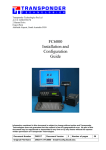
Cool Gas Micropropulsion system - TNO, TU Delft, UTwente
The micropropulsion payload system is designed in order to provide thrust for nanosatellite´’s positional and orbit correction. The system contains two advance innovations; (1) propellant compact storage in solid state and (2) highly integrated feeding and
thruster system based on MEMS technology. This unique innovation (gas storage and
release technology) currently developed at TNO for nitrogen, hydrogen and oxygen. The
engineering model of cool gas micropropulsion system is depicted in Figure 1.1.
During the flight mission, the performance of micropropulsion system will be evaluated under the space condition in order to prove that cool gas generator micropropulsion
system are space proven and ready to be implemented in the small scale satellite system.
1.2.2
Multifunctional Particle Spectrometer (MPS) - Cosine Research
BV
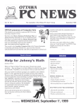
Multifunctional Particle Spectrometer (MPS) is a new type of radiation spectrometer
designed to protect spacecraft and its payload from radiations, such as protons, electrons and gamma-rays. MPS will fly onboard with Delfi-n3Xt not only for protection
1.2. DELFI-N3XT PAYLOADS
3
Figure 1.1: Engineering model (A) and a computer model (B) showing the cool gas
generator micropropulsion system [3]
purpose, but also to obtain key diagnostic data for scientific purposes. MPS designed to
be sensitive over large energy ranges and able to measure particles collision angle within
10 degrees. MPS tracker system board designed based on a Va32Ta ASIC (Application Specific Integrated Circuit) which contain 32 input channels with pre-amplification,
shaping, sample and hold and internal trigger. The readout module developed using
Xilinx FPGA that supported by Gaisler Research (Sweden). The engineering prototype
model depicted in Figure 1.2.
Figure 1.2: 3D Drawing of MPS [3]
1.2.3
Space Flash Memory - NLR
In the space system domain, the increasing demand of data storage is very high. In
other hands, the space proven memory chips available on the market are very expensive
and their data storage capacities are limited. Delfi-n3Xt will fly carrying Commercial
4
CHAPTER 1. INTRODUCTION
off-the-shelf (COTS) memory experiment from National Aerospace Laboratory of the
Netherlands (NLR). COTS memory is very sensitive to radiation, hence in order to use
it for space application there are several electronic protection circuits to be designed and
added to protect COTS memory against space radiations. There are two operation modes
during the mission; the autonomous mode and the storage mode. In autonomous mode,
the SPLASH controller will provide pseudo-random data and then write the number
into the memory. The COTS memory data then compared with pseudo-random data in
order to check the correctness. The storage mode basically will operate the space flash
COTS memory into standard storage mode where the memory will be used to store data
from another Delfi-n3Xt module experiment. The vision of this experiment is to develop
cheap, modular and radiation tolerant memory storage than can be used on small-scale
satellite.
1.2.4
Hydrogenated Amorphous Silicon Solar Cells - DIMES
Hydrogenated Amorphous Silicon (a-Si:H) provide an opportunity to produce a low
cost, lightweight and radiation hard solar cell. Since this solar cell is tend to degrades
especially on space environment caused by space radiation and prolonged illumination
effect, therefore the experiment to perform measurement of voltage current of this solar
cell is needed. This experiment will provide valuable information on the life-time usage
of this solar cell technology. During the mission on board with Delfi-n3Xt, this solar cell
will be measured and evaluated in order to provide performance degradation information
and then the gathered data will be compared to computer modeling result. Thus by this,
the verification and development of the computer modeling can be improved further.
1.2.5
Efficient Nanosatellite Transceiver Module - ISIS BV
Developed based on previous nanosatellite programme (Delfi-C3 ), ITRX is an efficient
and modular transceiver from ISIS Company. Compared with its predecessor, the Delfin3Xt ITRX carried out more power amplifier with high efficiency. Another advancement
is provided, such as highly modular design of the Delfi-n3Xt ITRX. The Delfi-n3Xt ITRX
provide transfer rate at 1200 bps for uplink and a maximum of 9600 bps for downlink.
In order to provide backup plan, for instance where there are less power available on the
satellite, Delfi-n3Xt ITRX can be reprogrammed via uplink commands. These command
can be varies and specific, for example a command that should be executed in order to
reduce the transmission power, where the default is at least 400 mW. The Delfi-n3Xt
ITRX will not only fly as a payload, but also as uplink receiver module where it can
be used as a backup command receiver for commanding the satellite. The main goal
for this experiment is to provide space proven and highly efficient transceiver, especially
used for small scale satellite communication.
1.3. DELFI-N3XT SUBSYSTEM
1.3
1.3.1
5
Delfi-n3Xt Subsystem
Electrical Power Subsystem (EPS)
Delfi-n3Xt will carry four Hydrogenated Amorphous Silicon solar cells that will be
mounted in the edge of the satellites structure. In order to obtain the maximum energy,
the four satellite solar cell will be pointed out directly towards the sun. The pointing
direction will be guided using wireless sun sensor technology. The expected maximum
power on the primary power bus is around 10 Watts. Moreover, Delfi-n3Xt also carries
the li-ion batteries on board to be used as energy storage and will be utilized when
the satellite operates in the eclipse mode. The Delfi-n3Xt EPS architecture depicted in
Figure 1.3.
Figure 1.3: EPS architecture [3]
6
CHAPTER 1. INTRODUCTION
1.3.2
Command and Data Handling System (CDHS)
Figure 1.4 shows the functional breakdown of CDHS. There are two major functions
of CDHS; receives, validates, decodes and distributes the commands toward another
satellite subsystem and gathers, processes and formats satellite data (i.e housekeeping,
mission data) for downlink purposes or use by the OnBoard Computer (OBC).
Figure 1.4: Functional breakdown of the CHDS [3]
In summary, Delfi-n3Xt CDHS developed based on single I2C bus. It similar to its
predecessor (Delfi-C3 ), however, the reliability of the bus system was improved. Moreover, in the OBC module, a real-time clock and data storage are provided. In order to
provide a module backup plan, for instance if the OBC fails to operates, there is another
(redundant) controller in the primary radio (PTRX).
1.3.3
Communication System (COMMS)
The COMMS subsystem provides an important communication element between satellite
and the ground segment. There are three main task provided by COMMS subsystem;
1. Gather and process housekeeping data from satellite to the satellite operator;
2. Gather and process payload data from the spacecraft to the users;
3. Receives telecommands from satellite operator (ground segment).
Compared to its predecessor (Delfi-C3 ), the Delfi-n3Xt COMMS include the Delfi
platform advancement; the implementation of STX, a high speed downlink radio (>9600
bps). The overview of Delfi-n3Xt communication subsystem depicted in Figure 1.5.
Delfi-n3Xt will fly and carry three radios onboard; PTRX, STX and ITRX radio.
PTRX is the primary radio transceiver reserved as receiver and transmitter for both
telecommands and housekeeping data. STX is the high speed radio transmitter for both
payload and housekeeping data. The STX speed of transmission is over 9600 bps. ITRX
is the experimental transmitter module from ISIS Company, which also functioned as
PTRX backup. Both PTRX and ITRX are based on Delfi-C3 radio amateur platform
(RAP), where the STX is an experimental module that will be utilized to downlink all
the experiments data specifically to Delft ground station.
1.3. DELFI-N3XT SUBSYSTEM
7
Figure 1.5: Overview of Delfi-n3Xt Communication subsystem [3]
1.3.4
Attitude Determination and Control Subsystem (ADCS)
ADCS can be described as the system that control and determine the attitude of the
satellite. There are two main modules in the ADCS; Attitude and Determination System
(ADS) and Attitude Control System (ACS). The ADS module will receives data from
the sensors, compute the attitude data and then forwards the result toward OBC and
ACS afterwards. In conjunction with ADS, ACS will receive computational result data
from the ADS and OBC then control the satellite in order to point it into preferred
location or coordinate. The Delfi-n3Xt´’s ADCS has three important operations, such as:
pointing satellite toward the sun perpendicularly in order to generate a maximum power,
tracking the ground station to perform specific missions (e.g. high speed downlink) and
perform scientific particle measurement using MPS module.
1.3.5
Structural Subsystem (STS)
As like its predecessor, Delfi-n3Xt will use a rod system as inner structure. Since about
one-third of satellite structure space will be reserved for MPS and Interconnect Board
(ICB) hence the use of detachable side panels is preferred. Delfi-n3Xt use three-unit
Cubesats standard dimension, therefore the dimension of the satellite will approximate
around 100 x 100 x 340.5 mm (exclude solar panels). At the top of the modular box
mounted deployable modular antenna boxes (MABs) and solar panels. These modules
however only need one single PCB with MABs. Both of antennas and solar panel deployment algorithm will be similar with Delfi-C3 , based on the thermal knife concept:
a high temperature resistor that cut the wire. The breakdown of Delfi-n3Xt structure
depicted in Figure 1.6.
1.3.6
Thermal Control Subsystem (TCS)
In order to keep the balance of all satellite module components (within their operation
and allowable limit), the TCS must provide a good balance between cold space and the
solar heat, planetary and onboard heat source. The main objective is to design the
TCS that does not need an active thermal control. In order to start the development,
a simulation using data gathered from Delfi-C3 satellite has been performed. Using this
data, the indicative satellite thermal behaviour can be modeled and then the result can
8
CHAPTER 1. INTRODUCTION
Figure 1.6: Delfi-n3Xt structure rendering breakdown [3]
be taken into account in the Delfi-n3Xt TCS design process. The Delfi-n3Xt satellite
thermal design process depicted in Figure 1.7.
1.4
Thesis Objective
Since the communication between satellite and earth ground segment is very important to
the mission, therefore this subsystem will be develop as good as possible in order to have
a successful satellite mission. In this project, the communication subsystem is divided
into two parts; the space segment communication and the earth segment communication.
The space segment, which is also referred to as the communication subsystem, can again
be split up into the radio part and the antenna system part. Onboard the satellite there
are a number of radios, which create the signals that are transmitted to the Earth and
which handle the signals received from Earth. The other part of the space segment is
formed by the antenna system, which is essential for transmitting to and receiving signals
from earth. In the other hand, the earth segment communication will be functioned as
the system that handles all signals that received from the satellite (via radio amateur
around the world) and to sends commands to the satellite in order to do specific task or
mission.
This thesis research will be focused on the data-handling system of the ground segment part. Delfi-n3Xt satellite makes use of global network of radio amateur and internet connection for receiving and collecting the continuous data telemetry in a central
database. Learning from previous system experience that was applied in the predecessor of Delfi-n3Xt, Delfi-C3 satellite, there were many flaws in the data-handling system
1.4. THESIS OBJECTIVE
9
Figure 1.7: (a) General input-output system and (b) Conceptual Delfi-n3Xt thermal
system [3]
of the ground segment due to a very late development of the system. Delfi-n3Xt will
make use of low speed continuous telemetry downlink and high speed downlink for passes
over Delft Central Ground Segment (DCGS). The low speed is very robust and proven
system, however since there is no global or full time coverage of radio amateurs, there
will be many gaps in the gathered data. The high speed downlink will send down all
measurements onboard the satellite, however because this component is a new system
which is also dependent on attitude control of the satellite, thus this system will be less
reliable. After analyzing the ground segment data handling system of Delfi-C3 , many
problems that make the DCGS not functioned correctly were identified, especially in the
telemetry software system part.
According to those the problems above, this thesis research is carryout to solve the
main research question of this project, that is: ”How to deliver data reliably and
secure in unreliable satellite communication system environment?” To fulfill
the main goal, the following research objectives have been pursued:
1. Analysis of Delfi-C3 problems with the ground segment data handling
system.
In this stage, problems of Delfi-C3 ground segment data handling are identified
10
CHAPTER 1. INTRODUCTION
and analyzed. This part is organized in three phases. First, provides a reference
system architecture, identifies global threats and vulnerabilities and performs a
risk assessment. Second, in this phase, possible solution candidates are identified.
And finally, evaluate the possible solutions regarding the number of properties such
as transparency, implementation feasibility, performance and conformance in order
to develop the good and reliable system of Delfi-n3Xt ground segment
2. Design of a data-handling system for Delfi-n3Xt mission which is less
prone to irreversible human error.
In this stage is mainly focused to design the new system for Delfi-n3Xt satellite
mission in system engineer level that solves the problems in the previous satellite
mission (Delfi-C3 ).
3. Developing ground segment application software for Delfi-n3Xt satellite
mission (that can be reused in other satellite missions).
This stage is mainly focused to develop a system software for the current satellite
mission. One big difference from previous system are: the data definition will be
made as flexible as possible (not hardcoded into the system) and will be made more
secure in terms of data transmission. This design paradigm is taken into account
in order to expands the purpose of the software system, not only for Delfi-n3Xt
satellite mission, but also can be used for other satellites mission around the world.
4. Proof-of-concept for the data handling system using Delfi-C3 data and
Delfi-n3Xt simulation.
This stage is mainly focused to perform alpha testing of the software system by
using Delfi-C3 data and Delfi-n3Xt simulation.
5. Reliability and performance software system testing.
In this stage, reliability and performance testing of the data handling software
system is performed. Various data stimuli were conducted. The idea of this phase
is to make sure that this system is reliable, flexible for the last changes of the
mission (i.e not directly hard-coded for the crucial part of the system like data
frame definition, communication protocol between satellite and ground segment),
have good performance, secure and can be used for next generation Delfi satellite
program or another satellite mission afterwards.
6. Implementation of the data-protocols of the satellite.
In this stage, the research, analysis and implementation data protocol part of Delfin3Xt satellite mission is performed. To be able to communicate with earth ground
segment, data protocol communication of the satellite should be determined and
matched. In this case, technical analysis with various data-protocols that already
exist is performed, such as AX.25, FX.25, KISS-TNC, AMSAT-DL, RLP (Radio
Link Protocol), PAMAS (power aware multi-access protocol), IEEE802.2-LLC
(standard protocol on data link layer level for application such as Wi-Fi, GPRS,
WLAN), NSP (Nano Satellite Protocol), XSTP (eXtended Satellite Transport
Protocol), SRLL (Simple Radio Link Layer) and TRANSAT (special protocol
from ESA). In every data protocol there are many advantage and disadvantage.
1.5. THESIS ORGANIZATION
11
In this phase, making a trade-off between all of them and selected the best and
suitable candidates or come-up with a new data protocol for Delfi-n3Xt satellite
mission is performed.
1.5
Thesis Organization
The thesis is organized as follows:
In Chapter 2, the concept, the technological overview, the system architecture and
the technology trends of satellite communication systems, including the communication
system that Delfi-n3Xt select and used for this mission will be presented. In Chapter
3, overview of Delfi-C3 Ground Segment and technical investigation of Delfi-C3 Ground
Segments results are presented. The design of Delfi-n3Xt Ground Segment to address
the problems of previous data handling system (Delfi-C3 ) is presented in Chapter 4.
In Chapter 5, the implementation and evaluation (including testing results) of the new
system is presented and discussed. Finally, Chapter 6 gives the conclusions and provides
future research directions.
12
CHAPTER 1. INTRODUCTION
Satellite Telecommunication
System
2
Satellite communication system is a vital subsystem in the satellite mission, such as for
monitoring various payloads and satellite condition (via downlink telemetry), performing
communication transponder, and commands the satellite to perform specific tasks/ missions. This chapter presents concept, technological overview and system architecture of
satellite communication system, ended with details of the chosen communication system
for Delfi-n3Xt satellite mission.
2.1
General Satellite Telecommunication System
L. J. Ippolito Jr. (2008), described the definition of communication satellite in general
terms as:
”A communications satellite is an orbiting artificial earth satellite that receives a communications signals from a transmitting ground station, amplifies it and possibly processes
it, then transmits it back to the earth for reception by one or more receiving ground
stations. Communications information neither originates nor terminates at the satellite
itself. The satellite is an active transmission relay, similar in function to relay towers
used in terrestrial microwave communications. The commercial satellite communications
industry has its beginnings in the mid-1960s, and in less than 50 years has progressed
from an alternative exotic technology to a mainstream transmission technology, which is
pervasive in all elements of the global telecommunications infrastructure. Todays communications satellites offer extensive capabilities in applications involving data, voice,
and video, with services provided to fixed, broadcast, mobile, personal communications,
and private networks users.”
In telecommunications infrastructure, the communications satellite is a vital element
to transmit information from node/area A to node/area B using the communication
satellite component [8]. The details of the communication infrastructure shown in Figure 2.1. Since the first launch, the emergence of satellite becomes important component
to solve terrestrial link problem using microwave, cable, or fiber network and offer many
advantages, such as [8];
1. Distance Independent Costs. The transmission cost of the satellite basically
more stable regardless the distance of transmission area.
2. Fixed Broadcast Costs. The broadcast cost of the satellite is independent,
which mean that the service does not depend on how many the receivers that
receives the digital data.
3. High Capacity. Satellite communication services are able to provide high band
widths communication link, range from 10s to 100 Mbps. This high bandwidth
13
14
CHAPTER 2. SATELLITE TELECOMMUNICATION SYSTEM
Figure 2.1: Telecommunications via satellite in the telecommunications infrastructure
[8]
able to perform high speed data transfers, such as video and audio.
4. Low Error Rates. Digital satellite data produced bit error in random chances,
therefore the correction or prediction technique can be analyzed using statistical
algorithms.
5. Diversity of User Networks. Wide coverage areas of the satellite link can be
used to solve the terrestrial communication problem, since the satellite terminal
can be placed on the surface, at sea and either fixed or mobile ground segment.
2.2
Satellite Communication links
The design and performance of communication of the satellite are significantly affected
by the free space (RF) link [16]. Figure Figure 2.2 depicted the base concept of satellite
link communication system. Furthermore, Figure 2.3 showed the steps that required
in order performing data transfer over the radio link. Bellow the required step of data
transmission [16]:
1. Data converted into digital frames packages,
2. Error detection and error correction is implemented to correct the data,
3. The bitstream can be encoded in different way,
4. Next perform bitshaping process,
5. The data is modulated,
6. The modulated signal is transmitted over the antenna and received by the receiver
antenna,
7. The data signal is then diverse into intermediate carrier frequency,
2.2. SATELLITE COMMUNICATION LINKS
15
8. Demodulated process is performed,
9. The data signal converted into a bitstream,
10. Data signal is decoded from bitstream,
11. Error detection and error correction is implemented,
12. The final result is framed data for further processing.
Figure 2.2: General concept of satellite communication system [6]
Steps (5) until (10) are necessary taken to process analog data. Since data can
be corrupted during data transfer, coding technique is implemented (steps (1) and (3)
applied on the space segment and steps (11) and (13) on the ground segment [16].
2.2.1
Satellite Communication Protocols
There are the numbers of satellite communication protocols designed to perform the
wireless data communication. Many protocol has been developed to accommodate the
needs, however not all of those protocols are suitable for single university Cubesat.
Bellow commonly used communication protocol for small or Nanosatellite platform [16]:
1. AX.25. The standard protocol for digital transmissions of radio amateurs, which
is also known as ”packet radio”. The AX.25 protocol is the most commonly used
protocol for digital data transmission in the amateur radio service. It is a protocol
which is not dependent on datarate. This protocol can be generated by a device
called Terminal Node Controller, or TNC, which converts the digital data to a
modulating signal and vice versa and takes care of other protocol issues. This
16
CHAPTER 2. SATELLITE TELECOMMUNICATION SYSTEM
Figure 2.3: General layout of top level RF link satellite communication system [16]
TNC can be directly connected to a personal computer (PC). In amateur satellite
operations the TNC is operated in KISS (”Keep It Simple Stupid”) mode which
provides for a transparent way of data transfer between the PC and the TNC.
2. AMSAT-DL. This is the protocol as it is used on all AMSAT Phase 3 satellites.
It is less common within the amateur radio community and would require more
dedicated software to receive and process.
3. RLP. Radio Link Protocol, used for e.g. GSM networks;
4. IEEE802.2-LLC is the standard protocol on data link layer level for applications
such as Wi-Fi, General Packet Radio Service (GPRS), and Wireless Local Area
Network (WLAN);
5. NSP (Nanosatellite Protocol). This is a special protocol that dedicated for
nanosatellite communication purpose.
6. XSTP (eXtended Satellite Transport Protocol). This is a custom protocol
that developed by the University of Toronto (Canada) for their Can-X satellite
series mission. This protocol was derived from AX.25 standard protocol.
7. SRLL (Simple Radio Link Layer). This is a custom protocol communication
based on the AX.25 protocol that has ability to cancel the error and correct it to
the original data. This protocol is developed and introduced by Tokyo Institute of
Technology.
2.3
Delfi-n3Xt Communication System
The communication system (COMMS) of Delfi-n3Xt has three primary tasks [16]:
2.3. DELFI-N3XT COMMUNICATION SYSTEM
17
1. To get housekeeping data from the satellite to the satellite operator;
2. To get payload data from the satellite to the users;
3. To get telecommand from the satellite operator to the satellite.
The advancement communication system of Delfi-n3Xt will includes the implementation of STX payload. Overview of Delfi-n3Xt communication system is depicted in
Figure 2.4. Communication system of Delfi-n3Xt consists of 2 parts; the space segment
and the ground segment.
Figure 2.4: Overview of Delfi-n3Xt communication system [17]
2.3.1
Delfi-n3Xt Space Segment
Based on the observed mission, there are two communication system on board with
the satellite; the high-speed downlink and ITRX transceiver [17]. Those systems provided uplink and downlink functionalities. Since both high-speed downlink and ITRX
transceiver are used for experimental only, therefore the needs of another communication
system required in order to perform housekeeping and payload data transmission, this
communication system named as the primary transceiver (PTRX). In the end, there are
three radios on board of Delfi-n3Xt [17]:
1. PTRX: the primary receiver for telecommands, and transmitter for housekeeping
data and payload data;
2. STX: the high-speed downlink transmitting both payload and housekeeping data;
3. ITRX: ISIS transceiver payload.
2.3.1.1
Linear Transponder
Delfi-n3Xt’s PTRX designed to have a linear transponder in order to provide a service
toward radio amateur in favour of using their frequency. PTRX linear transponder
(Figure 2.5) consists of two parts; power splitter (extra amplifier stage in the uplink
signal path) and power combiner in the downlink path [17]. In order to allow radio
18
CHAPTER 2. SATELLITE TELECOMMUNICATION SYSTEM
amateur to use the Delfi-n3Xt communication service, transponder should be deployed
and activated. A number of components that included and implemented in the linear
transponder are [17]:
1. A power splitter in the uplink signal,
2. An amplifier, and
3. A power combiner.
Basically, on the RAP mode, the radio is switched from telemetry mode into transponder
mode; where the radio is stop generating any telemetry signal instead of turning on the
power amplifier of the linear transponder. However, at the moment the decision is still
unclear, whether this concept will be done in the PTRX mode [17].
Figure 2.5: The linear transponder block design [17]
2.3.1.2
Delfi-n3Xt Communication procedure
Figure 2.6 depicted the operation of the communication system of Delfi-n3Xt. Payload
and housekeeping data will be transmitted using PTRX while at the same time ITRX
transmitter is off and the STX beacon is turn on. Bellow four possible scenarios of the
communication operations [17]:
1. ITRX is on. This means that ITRX transmitter is on and performs the experiment
mode. This operation can be done by sending a telecommand,
2. Switch STX to TM mode. This mode can be activated using telecommand or
automatically when satellite knows that time to perform high-speed transfer occurs.
PTRX is used to send payload and housekeeping data while ITRX is off. After
satellite passed the high-speed transfer area, then satellite switches back in the
previous communication mode,
3. ITRX for housekeeping and Payload mode. In this mode, PTRX is off while the
house keeping and payload is transmitted using ITRX. This mode occurs when the
ITRX were better in the data rate or power consumption than PTRX,
2.3. DELFI-N3XT COMMUNICATION SYSTEM
19
4. Transponder on. PTRX is in the transponder mode and retransmit (a Morse
beacon) signal received in the uplink path. In the other hand, the ITRX is powered
off and STX beacon is on. This mode can be reset using a telecommand.
Both ITRX and PTRX receiver in the communication system are able to receive a
telecommand during all four above modes.
Figure 2.6: Operations of the communication system [17]
2.3.2
Delfi-n3Xt Ground Segment
The ground segment or also often called Ground Support Network (GSN) is considered one of vital communication system since it handles wireless data transmission from
satellite to Earth (downlink) and perform data transmission from earth to the satellite
(uplink). the Delfi-n3Xt’s ground segments is divided into three parts [16] [37]:
1. Delft Command Ground Station: this ground station is located at Delft and will
be used as primary station to receive housekeeping and payload data from satellite
and sending telecommand to the satellite. As back up, ground segment located at
Eindhoven University of Technology will be used.
2. Radio amateur network worldwide. There are a wide community of people that
interested in amateur satellite. They played important role by receiving telemetry
20
CHAPTER 2. SATELLITE TELECOMMUNICATION SYSTEM
data from all over the world and sending the received data to Delft ground station
over the internet link to be processed further.
3. Global Educational Network for Satellite Operations (GENSO): a large number of
university ground station worldwide formed a link connected network. It is still
in the development phase, however, it suggest an interesting added value to the
ground segment. This large network link primarily will be used to receive the data
telemetry and processed further.
Delfi-C3 Ground Segment
3
Telecommanding and receiving data telemetry to/from the satellite is an important and
crucial task for many satellite missions. To achieve this purpose, the ground segment
should be prepared very well in the terms of technological used both on the hardware
and the software sides. This chapter will present an overview, technology architecture
(both hardware and software) and roles of ground segment of Delfi-C3 . This chapter also
presents the Delfi-C3 ground segments technical analyze result, especially in the software
side in order to solve the problems that occur in the current satellite mission.
3.1
Overview of Delfi-C3 Ground Segment
A satellite communications system can be seen as a sequence of different elements with
the ground segment as the most important of it [37]. The functionality of a proper
satellite system design relies on the ground segment. Figure 3.1 shows the breakdown of
the ground segment along with the identification of its element and their functionalities.
Figure 3.1: Delfi-C3 ground segment system break down [37]
The primary ground segment of the Delfi-C3 located at Delft University of Technol21
22
CHAPTER 3. DELFI-C3 GROUND SEGMENT
ogy is used to receive telemetry and telecommand the satellite. It is consists of three
main parts: receiving telemetry data, as central server and as radio amateur [37] [28].
The first part itself can be separated further into three blocks: the ground station at
Delft University of Technology, the backup ground station at Eindhoven University of
Technology, and the more than hundreds radio amateurs around the world which is used
as additional telemetry reception worldwide.
In this mission, the data frame, send by the satellite, will be received by the ground
segment through the antenna of the ground station in Delft and the radio amateurs
around the world. The data from the radio amateur is sent to the Delfi-C3 team through
the internet (Figure 3.2). The central server located in Delft, once it receives the data,
it will collect, store, and process the data frame to obtain the proper information asked
by the users.
Figure 3.2: Delfi-C3 ground segment communication architecture [16]
3.1.1
Delft Command Ground Station
Delft Command Ground Station (DCGS), located at the Delft University of Technology,
will be the Delfi-n3Xt primary ground segment. The DCGS will be the main ground
station to send telecommands, receive payload and housekeeping data, as well to receive
high-speed downlink from the satellite.
The block diagram of system operations on the DCGS can be seen in Figure 3.3.
ARSWIN is a software to control the antenna rotator and display both azimuth and
elevation based on the Orbitron (the satellite tracking system). On the other hand,
DARCA (Delfi Antenna Rotator Control Application) is a software which task is to read
the speed and the direction of the wind [19]. When both of them are in correct conditions,
3.1. OVERVIEW OF DELFI-C3 GROUND SEGMENT
23
Figure 3.3: Block diagram of system operations at Delft-CGS [19]
ARSWIN will connect to the rotor to move the receiver antenna. The downlink process
will start, after the antenna is linked to the satellite.
RASCAL (Radio Amateur Satellite Communications Autonomous Logger) is a software that process the received data. It demodulates the signal, handles the protocol,
extracts the data from frames, and finally cuts and sends them to the Delft central server
through the internet [37]. In nominal mode, for security reason, uplink is only possible from DCGS. However, in case of failure, the ground station located at Eindhoven
University of Technology will perform as a ground segment backup.
3.1.1.1
Telecommand Uplink and Telemetry Downlink
DCGS hardware configuration [37]:
1. M2 2MCP14 VHF circularly polarized yagi antenna, switchable RHCP / LHCP,
2. M2 436CP30 UHF circularly polarized yagi antenna, switchable RHCP / LHCP,
3. ICOM IC-910H VHF / UHF all-mode transceiver,
4. ICOM CT-17 CI-V PC-transceiver interface,
5. YAESU G5500 Azimuth / Elevation rotor with control box,
6. EA4TX Rotor interface board,
7. Symek TNC-31S Terminal Node Controller with modem disconnect header,
CHAPTER 3. DELFI-C3 GROUND SEGMENT
24
8. Custom made Manchester modulator and BPSK demodulator,
9. Personal Computer running Orbitron tracking software,
10. Several Power supplies.
Above mentioned requirement are designed in order to support Delfi-C3 operation.
However, the following items have been added to the ground station in order to support
another satellite mission [37];
1. KEPS 60cm 2.4 GHz antenna and patch feed,
2. SSB Electronic SP7000 UHF Low Noise Amplifier,
3. Transystem AIDC 3731 Downconverter, modified to 145MHz IF output,
4. IFD TNC7-Multi 1200Bd AFSK / 9600 Baud FSK TNC.
For Delfi-C3 satellite mission, a software modem solution using the PCs soundcard is
developed to allow fexibility and digital signal processing possibility on the received signal
[37]. Furthermore, it gives the benefits of demodulating the backup OBM modulation
using easy means.
The overview of the current ground station setup can be seen in Figure 3.4. A second
similar ground station will be setup in the near future. It will facilitate testing, act as a
backup ground station, and/or enable the deployment of a remote ground station. For
the telemetry downlink, the Distributed Ground Station network uses RASCAL. On the
other hand, a software called DUMB (Delfi-C3 Upload Management and Broadcasting
software) is already written (beta version) for generating the telecommand uplink data
and can optionally be integrated with the Distributed Ground Station software package.
3.1.1.2
Delft Ground Segment Central Server
RASCAL is the link between all of the world wide ground stations and the central server.
RASCALs task flow can be explained as follows [38]:
1. Demodulates the digital data frame,
2. Handles the protocol communications,
3. Implement the FEC,
4. Extracts and cuts digital data from the frames,
5. Sends the data to DCGS.
FEC (Forward Error Correction) checksum is implemented for error checking and it
is already a part of the protocol used (radio amateur protocol AX.25). The whole frame
will be deleted if the checksum is not match. Otherwise, the data frames that already
being cuts are sent toward DCGS. There, these data will be compared to other data
coming from different ground stations, filtered and stored in a database [38]. Further
data processing comprises of formatting and compiling the data which will be sent to
the users as shown in Figure 3.5.
3.1. OVERVIEW OF DELFI-C3 GROUND SEGMENT
25
Figure 3.4: Delfi-C3 command ground station equipment [37]
3.1.2
Eindhoven Command Ground Station
Located at Eindhoven University of Technology is a backup ground station with similar
capabilities to DCGS. As a backup, it is only used for the Delfi-C3 whenever a failure in
the DCGS occurs. For the Delft-n3xt mission, the function of this station, particularly
in regards to whether it will also receive the STX signal in high-speed mode, is still in
TBC (to be confirmed) status [17].
3.1.3
Worldwide Radio Amateur Network
Universities which conduct an active satellite research program will also have a ground
station. However, the cooperation and information sharing on ground station development has been very little and also, most of the design of their satellite only allows the
ground station to communicate with it once it is in the view of their ground station.
Because of this, their satellite get underused since the amount of time the satellite is in
view of the ground station is low. If it is possible to communicate with the satellite via
a distributed ground station network from anywhere of the world, it would be a great
advantage.
In this mission, amateur satellite operators around the world form the distributed
ground station network. To allow the amateurs to decode the telemetry data from the
satellite, the Delfi-C3 team will make the software available for free. However, the user
is required to transmit all data in ”plain language”, or to publish all details required to
decode it. An exception only on the uplink telecommand, where the data frame should
be encrypted.
R. Reijerse (2008) first made the design of the telemetry software [22]. RASCAL en-
26
CHAPTER 3. DELFI-C3 GROUND SEGMENT
Figure 3.5: Data processing in DCGS [38]
ables the ability to convert the BPSK signal to serial data by using a TNC at the amateur
ground station. In addition, to directly demodulate the data stream, PCs soundcard can
be opted, which is perfectly possible with the chosen BPSK downlink modulation [37].
Again, for the Delfi n3Xt satellite mission, contribution from the radio amateur community in collecting telemetry is carried out again. Since most radio amateurs have
equipment for VHF band frequencies, the main link which the radio amateurs will received is the PTRX/ITRX downlink in the VHF band. The STX signal will be received
by fewer radio amateurs due to the need of the equipment for 2.4 GHz to receive the
STX link, which is less common amongst radio amateurs [17].
3.2. DELFI-C3 GROUND SEGMENT SOFTWARE
3.2
3.2.1
27
Delfi-C3 Ground Segment Software
Satellite Tracker (Orbitron)
Orbitron developed by S. Stoff (2001), is a satellite tracking system which is used for
radio amateur and is considered as one of the best programs for satellite tracking and
orbit determination. Because of that reason, it is adapted by the DCGS ground station.
It uses Kepler elements as input constants for the standard mathematical algorithm
to determine satellite orbits. In addition, through DDE (Dynamic Data Exchange)
interface, Orbitron is capable of sending the satellite position to third party software
programs, which in this case, ARSWIN [19].
Figure 3.6: Orbitron main screen (tracking Delfi-C3 )
3.2.2
RASCAL (Radio
tonomous Logger)
Amateur
Satellite
Communications
Au-
RASCAL is a free telemetry software which are offered to radio-amateurs all around the
world by Delfi-C3 team to be able to collect and decode data of the Delfi-C3 satellite [22].
It is done by decoding the received audio data frame on the computer’s soundcard which
is coming from a transceiver that track the Delfi-C3 satellite. RASCAL also stores and
forwards the telemetry to DCGS data collection servers, in addition to decoding and
making the telemetry information visible to the users. Figure 3.7 depicted the main
screen of RASCAL.
CHAPTER 3. DELFI-C3 GROUND SEGMENT
28
Figure 3.7: RASCAL main screen [22]
3.3
Delfi-C3 Ground Segment Technical Problem (RASCAL)
As mentioned before, to receive and collect the continuous data telemetry in a central
database (DCGS), Delfi satellite makes use of global network of radio amateurs and
their internet connections. For Delfi-C3 satellite, because of a very late development of
the system, there are many flaws in the data-handling system of the ground segment
(especially RASCAL). As part of Delfi-C3 satellite project, it is very important for
RASCAL to decode the payload/telemetry data frames from satellite and sends it to
the DCGS for further processing.
3.3.1
Overview of RASCAL
Bellow the main data flow process and functionality from RASCAL telemetry decoder
software [22]:
1. First, the satellite sends payload and housekeeping data down to the earth,
3.3. DELFI-C3 GROUND SEGMENT TECHNICAL PROBLEM (RASCAL)
29
2. Radio amateurs’ ground station want to view the data from the satellite. RASCAL
provides Graphical User Interface (GUI) functionality to display the data frame in
the interactive way,
3. Final step, RASCAL will forward the received telemetry data to a central database
server (DCGS) for further processing. This forwarding is done using the internet
connection.
There are some major updates since it first release, the updated part listed as follows
[39]:
1. Added AX.25 radio amateur communication protocol library,
2. Added the Telemetry Definition which hard coded into the application,
3. Added a new GUI (graph viewer),
4. Added generic processing module of AX.25 frames,
5. Added many functions and classes.
The RASCAL implementation for satellite data communication flow is presented in figure 3.8 bellow:
Figure 3.8: Ground Station Network data flow [39]
3.3.2
RASCAL’s Software/Code Investigation
The investigation in this stage is focused on the RASCAL’s code as one big entity. Furthermore, this investigation is done by using software engineering analysis (in term of
30
CHAPTER 3. DELFI-C3 GROUND SEGMENT
software quality), behavioral and functionality software analysis, the correctness of the
design analysis, and also structure of the design code analysis to performs deep and complete investigation from top level until real byte of the code from software engineering
point of view. In this way, RASCAL can be investigated thoroughly in order to find
bugs in the system, to update and do correction in the system and add another vital
implementation (i.e add new system algorithm in order to perform a better software functionality) in the system. Based on the result of this investigation, a new system/software
can be developed which has much better and rich functionality and reliability for further
projects (Delfi-n3Xt satellite mission).
RASCAL was made using Java platform/ programming language from Sun Microsystems. The idea to develop RASCAL under this programming language is that Java is
not only free license /open source software but also it is platform independent. Thus,
RASCAL can be free of charge (for licensing purpose) and of course it can run well in
multiple operating systems. Beside those advantages, the usage of Java is due to the
fact that Java is one of the best OOP (Object Oriented Programming) languages that
make the development of complex software [2] [23]. This approach not only eases the
development process, but it also enables easy maintenance of the software code in order
to do updates and do corrections for further development.
After deep code analysis it can be seen that the RASCAL code contains separate
libraries and packages. In those packages, the classes were grouped and implemented
based on the processing block functionality. The data processing flow algorithm and
the class diagram structure of RASCAL is presented in Figure 3.9 and Figure 3.10
respectively.
Figure 3.9: RASCAL data processing flow algorithm [35]
3.3.3
Result of RASCAL Investigation
Careful investigation of RASCAL system is done by using two important software analysis steps. First step is using pattern code detection to classify the library, object and
class structure of the system. By this method, it can be understood all the libraries,
objects, classes and it is interconnect and functionalities between them. Second step is
by using byte-code architecture software analysis to perform the correctness-check and
3.3. DELFI-C3 GROUND SEGMENT TECHNICAL PROBLEM (RASCAL)
31
Figure 3.10: RASCAL class diagram overview [22]
evaluate the quality of the software based on the algorithm and real byte-code implementation on the system. With this method, the software structure and quality can be
evaluates thoroughly in order to verify the correctness of the algorithm and monitor the
byte-code software structure and architecture implementation.
As result, several weaknesses in the system have been found due to very short time
of system development process. Starting from top level layer system that is the GUI
(Graphical User Interface, this GUI part still need to be improved as recommended by
some user / radio amateurs) until deep level layer on real algorithm and code implementation that caused several data processing functionality not working properly. For
further detail of the investigation results can be described as follows:
1. RASCAL was built completely based on the OOP concept (with IDE), however
there is inconsistency in class naming and method functionality. This implementation sometimes caused some method/function rewritten twice or more in the
different object or class in order to do the same function. Based on author experiences, this will cause the code to be larger and slower for JVM (Java Virtual
Machine) to execute and also will cause the delay of some actions. This is especially
important for critical timing actions;
2. To decode the telemetry and have connection with TNC (terminal Node Controller), the AX.25 class library has been made. This class originally was adopted
32
CHAPTER 3. DELFI-C3 GROUND SEGMENT
from standard radio amateur data communication protocol AX.25. However, there
are some problems on that class due to incorrect system algorithm implementation that made the AX.25 library comply with the AX.25 specs (incorrect bit data
length implementation). Some attention needs to be paid to perform intensive
testing of this library. And also theres a wrong algorithm implementation that can
cause telemetry data to be handled incorrectly;
3. The lack of unique frame identifiers in RASCAL’s algorithm i.c.m. with improper
time-stamping, making it hard to filter out the redundant data or even to reconstruct the chronology;
4. There was an error in the CRC handling system, thus corrupted frames still pass
through;
5. The algorithm of RASCAL cuts the data that it receives from the satellite into
pieces then processes it for displaying purposes (in GUI). However, as depicted
in Figure 3.19, RASCAL sends the cut data to the DCGS (Delft Central Ground
Station) server that originally should not be done in such way (only raw data that
should be sends to DCGS). RASCAL’s problems was not only sends the segmented
data, but also segmented/ cut the data wrongly, thus, on the DCGS a lot of manual
work needs to be performed in order to reconstruct the original raw data. For the
next software system, it will need to have some algorithms that can provides two
actions (i.e bridging algorithm that cuts the pieces of raw data only for client
displayer purposes and directly forwards the raw data to the DCGS server).
6. There are possibilities to have segmentation fault or overflow in RASCAL. In the
current implementation, the INT (integer) variable is used frequently (to handle
bit related data), with all the consequences for the reusability of the software in the
future, in the next software versions a byte array should be used instead. By using
a byte array the danger of exceeding the number of bits can be eliminated. A byte
array is also customisable to the number of bits that are needed (it can be set as
a constant to meet the requirement of satellite data budget). This approach also
will make the last minutes changes/updates without having risks of data overflow.
7. Concerning the security and authentication of the data, RASCAL only implemented a very basic security and authentication module and algorithm. Thus,
there is a possibility for attacks by outsiders (crackers). The current RASCAL
only encrypted the data with just a MD5 algorithm due to improper implementation of security methods and algorithm. For future software, another security
system should be used. One of the scenarios that can be implemented is the following. The Delfi-n3Xt client software sends a user name and gets two salts, one
static salt and a random salt for the authentication session. A salt is a sequence
of bits added to a password to make the decryption of the password more difficult.
Then the Delfi-n3Xt client software and the server generate a digest using MD5
encryption algorithm. The onetime digest is transferred to the server to authenticate. When the two digests match the authentication has succeeded. In this
3.3. DELFI-C3 GROUND SEGMENT TECHNICAL PROBLEM (RASCAL)
33
way, the Delfi-n3Xt client software will have good security system compared with
previous system.
8. For the installation package, current RASCAL system still used the conventional
method, that is do the manual ”copy-paste” to place the driver into specific directory. This sometime can cause the host system not to work properly if the user
is not familiar with the operating system. Thus, to prevent these issues, for the
next system a better software packaging should be used to avoid the complexity for
installing the software system on specific operating system and for easiness purpose
from different user level.
9. RASCAL’s GUI (Graphical User Interface) needs to be improved. Based on a survey research that the author made between some RASCAL users (radio amateurs),
a more interactive GUI is desired that displays graphs of telemetry channels over
a certain period of time. By this they can analyze the status of some parameters
by looking to the graph instead of looking at numbers only.
10. On the desktop of RASCAL, there are two ways of displaying the values of the
telemetry: in a graph and in a table. There is a way needed to properly display
the single bit values from telemetry data frame (that already cut by the protocol)
on the graph view mode, because the current RASCAL still have a problem while
trying to display this kind of bit value model on graph view mode.
11. AX25 Library (in RASCAL) was made for communication-interconnects purpose.
In that library, it needs a better error handling. In the current RASCAL, when
loading the external javax.comm drivers, some error handling should be done.
Previous developers did not succeed to catch this errors handling.
12. Displaying the IV Curves in a graph did cause some trouble. Previous developers
decided to use a default scaling but did not have a chance of really test it since
the automatically generated value does not represent a curve. These issues should
be tested and probably a few updates should be done on the code. For the next
system bugs related to this issue need to be fixed and implemented on the other
graph modules.
13. Concerning GaAs telemetry fields on RASCAL: it is not necessary but it might be
handy to create a separate GaAs definition and value class (just for convenience
from software engineering point of view). Currently, the GaAs fields are contained
in single value (TelemetryValue) objects. Based on that fact, for next system, this
part needs a special way to display the single bit value. This issue (related to the
class code refactoring) will be applied in the Delfi-n3Xt client.
14. In the latest RASCAL version, the protocol (including frame library module setting) is deeply hardcoded in the system code. Based on this fact, it will be a lot of
manual work if there is a change or a last minute update. Thus, for the next system (Delfi-n3Xt client), the protocol (and related flexible library) will be made as
flexible as possible by putting it in the initialization/configuration system file (i.e
text mode configuration file) then controlled by some system class. In this way, if
CHAPTER 3. DELFI-C3 GROUND SEGMENT
34
there are last minute changes (i.e concerning data budget or anything later) it will
be much easier to update the protocol system from this configuration file instead
of go deeply on to the codes and recompiles the codes again from beginning.
15. RASCAL only uses the PC local system timer format for packet-frame timer purpose, which should be using Universal Time Coordinate (UTC) timer format instead to make it easy for data reconstruction process.
16. RASCAL does not have network connection check (updatable in every second for
example), hence if in the middle of data sending process to DCGS server there are
network interruptions, the data packets will be lost without being saved into user
PC local database.
17. A lot of variables/parameters are directly hardcoded into the codes. To prepare
for last minute data update and to avoid waste of time for debugging purpose deep
into the codes in the critical time, it much better for the next telemetry system
those variables/parameters developed as flexible as possible, not hardcoded into
the codes.
18. Suggestion for RASCAL’s look-and-feel, some attention needs to be paid to the
main housekeeping and payload data display. The displaying of the values of the
telemetry that use single bits is clear. However, to display them more clearly the
values need to be decoded properly and they need to be displayed independently
to make the GUI more convenient to see and easy to understand/ analyzed by the
user if those data can be displayed with clear data category (i.e in separate panel
tab).
19. The current RASCAL version is based on the JDK (Java Development Kit) 1.6
and NetBeans 5.1. Since this version of the development tool has several bugs
(information released by the vendor [7]), for the Delfi-n3Xt data handling system it
will better to use the current latest technology/ development tools to keep updated.
The usage of the current latest technology/ development tools will have so many
benefits and advantages. Not only solved the issued bugs, but also the latest
technology development tool will also provide the stability, rich of functionalities
and capabilities that can be used for complex developing purpose. Since the current
RASCAL not yet supported with this latest technology development tool, then it
is better to develop Delfi-n3Xt client starting from the scratch instead of doing
reserve engineering on the previous version.
Besides the above technical problems, there are also non/semi-technical problem
accours, such as there was no planning of the complete procedures from sensing
to translation of data, there was not consideration for all non-nominal cases and
almost complete lack of documentation.
3.4
Lesson Learned
The points described above are the RASCAL’s facts that need to fixed and improve for
next satellite mission (especially Delfi-n3Xt). Those points are maybe able to increase
3.4. LESSON LEARNED
35
during further investigation with real data implementation. Therefore, it can be concluded and advised that it is better to develop new system for Delfi-n3Xt data handling
system with latest version of technology development tools in order to have high stability
and good performance of ground segment data handling system software for the next
satellite mission instead of doing reverse engineering from previous system (related with
point 19 of the investigation result).
36
CHAPTER 3. DELFI-C3 GROUND SEGMENT
Design of Delfi-n3Xt Ground
Segment (DUDe)
4
This chapter presents the design of ground segment data handling system for Delfi-n3Xt
satellite mission. The problems identified on the previous data handling system (Delfi-C3
satellite mission) are addressed and properly solved. As presented in the previous chapter,
there are many issues that need attention and have to be solved in order to guarantee a
successful mission on Delfi-n3Xt satellite mission, starting from designing of new data
handling system, upgrading of some DCGS hardware devices according S-Band usability
on-board in the satellite and developing a new telemetry downlink decoder to replace the
RASCAL software.
4.1
Delfi-n3Xt Ground Segment Design
The ground segment or also often called Ground Support Network (GSN) is considered
as communication system part since it handles data transmission from satellite to Earth
(downlink) and perform data transmission from earth to the satellite (uplink).
4.1.1
4.1.1.1
Delft Command Ground Station (DCGS)
Top Level Design Overview
As shown in Figure 4.1, the Delfi-n3Xt ground segment design is similar to Delfi-C3 and
the major different are the additional STX module and worldwide link ground station
so called GENSO. In Delfi-n3Xt satellite mission, Delft ground station shall also receive
downlink signals from both PTRX and ITRX in VHF range of 144.00-147.00 MHz, since
the satellite is transmitting in the band 145.80-146.00 MHz [17]. As a backup, ground
segment located at Eindhoven University of Technology is used. This ground station
has similar capability with DCGS. DCGS that located at EEMCS faculty will be the
primary ground segment, which provide telecommand uplink and downlink functionality.
Since Delfi-n3Xt carried the STX communication onboard, the DCGS also becomes the
primary station to receive the high speed link from the satellite.
4.1.2
World Wide Radio Amateur Network
Based on the successful of previous satellite mission, Delfi-n3xt will use the same approach that use of the radio amateur community to collect the telemetry around the
orbit. Radio amateur will collect and decode the satellite data using decoder software
that will be distributed worldwide. Using this software, they are able to monitor the
satellite condition in real-time mode. Since Delfi-n3Xt equipped with experimental STX
communication system, not all the ground segment will able to receive and decode the
37
38
CHAPTER 4. DESIGN OF DELFI-N3XT GROUND SEGMENT (DUDE)
Figure 4.1: Delfi-n3Xt ground segment top level design overview
data from STX [36] [17]. To be able to receive the STX data, the ground segment should
have the equipment for 2.4 GHz frequency band.
4.1.3
GENSO (Global Educational Network of Satellite Operation)
GENSO is an ESA initiative project to connect the ground station from university all
over the world. With this concept, it will allow the global coverage from non-local
satellite available on the orbit. Moreover, GENSO station will provide the functionality
to send telecommand to some specific satellites, thus a satellite still can be controlled
and monitored after it phased the orbit area [30]. However, for security reason, at the
moment, the specific frequency data of Delfi-n3Xt is not available into the public yet
[17].GENSO world participations map and communication architecture depicted Figure 4.2 and Figure 4.3 bellow.
Basically, GENSO manage two kinds of passages of satellites: active and passive.
Passive passes only concern to the telemetry downlink (RX) and can be programmed
independently by a ground station, while Active passes involve both RX and the uplink
of telemetry (TX) and have to be requested by mission controls and negotiated between
mission controls and ground stations [30]. In the case of passive downlinks, the downloaded data is stored in the local ground station and will be forwarded to the mission
4.2. DUDE (DELFI UNIVERSAL DATA EXTRACTOR)
39
Figure 4.2: GENSO world participation’s map [29]
control user based on request. On the other hand, when satellite is in the active passes, a
connection between the satellite and the mission control is directly established. This can
be achieves by tunneling through the software application in the ground station server
(GSS).
In GENSO concept, both ground stations (GSS) and mission controls (MCC) will
continuously exchange control and status messages with the authentication server where
all network traffic is digitally signed and strongly encrypted using state of the art SSL
(Secure Socket Layer)/ TLS (Transport Layer Security) techniques [31]. The network
protocol is open and utilizes XML to structure the data. As a consequence it is possible
not only to extend the applications after GENSO has been publicly released as open
source, but also to develop applications acting as GSS (Ground Station Server) or MCC
(Mission Control Client) in different languages [30] [24].
4.2
DUDe (Delfi Universal Data Extractor)
Delfi-n3Xt satellite will make use of worldwide radio amateur community and internet connection for receiving and collecting the continuous data telemetry in a central
database (DCGS). For Delfi-C3 satellite mission, there were many issues and drawbacks
in the data-handling system of the ground segment (especially RASCAL) due to a very
late development of the system. In order to solve that mentioned problems, the new
telemetry system called DUDe is introduced and developed. This telemetry system will
replace the RASCAL telemetry system for Delfi-n3Xt satellite mission.
DUDe stand for Delfi Universal Data Extractor. DUDe is free telemetry software
offered by Delfi-n3Xt team. With the software, all worldwide ground station will be
able to collect and decode telemetry data that not only comes from Delfi-n3Xt satellite,
but also other CubeSats that already exist around the world (i.e CANX/Canada, SwissCube/Swiss, CUTE/Japan, etc.). As the U letter from DUDe that is mean Universal,
the DUDe design philosophy is to make a telemetry system that can be widely used or
universally used for other available satellite. For the telemetry receiving purpose, DUDe
40
CHAPTER 4. DESIGN OF DELFI-N3XT GROUND SEGMENT (DUDE)
Figure 4.3: GENSO communication architecture [30]
does this by decoding the incoming audio-signal on the system’s soundcard or from TNC
(Terminal Node Controller) that is received from a radio transceiver tuned to Delfi-n3Xt
bands or other satellites telemetry downlink frequency. DUDes another functionalities
are to decode and present the telemetry information that visible to the users. Similar
to RASCAL [22], DUDe also stores and forwards the telemetry to Delft DCGS data
collection server(s). In the developing process, DUDe was developed by using the latest
version of Java technology development tools in order to have high stability and good
performance of ground segment data handling system software for the mission instead
of doing reverse engineering from previous system (RASCAL).
4.2.1
Delfi-n3Xt Satellite Data Telemetry (Data Budget)
One of the important functions of the CDHS (Command Data Handling Subsystem)
is transferring the data from the satellites payloads and subsystems to the PTRX and
STX transceiver [10]. Two different telemetry types are distinguished in the telemetry
stream send by the satellite to the DGSN, housekeeping data (HK) and payload data
(PL). Payload data is data that generated by partners payload on the satellite and
housekeeping data is data that produced by satellite which contain satellite internal bus
status information [10] [17].
4.2. DUDE (DELFI UNIVERSAL DATA EXTRACTOR)
4.2.1.1
41
Satellite housekeeping data
Only data that generated by ITRX will be handled as housekeeping data which
contain many information from satellite subsystems. Bellow the details of Delfi-n3Xt
housekeeping data format [10] [11];
PTRX and ITRX housekeeping data contains:
• Current Rx-part = 8 bit
• Current Tx-part = 8 bit
• Forward power = 8 bit
• Reflected power = 8 bit
• Power Amplifier (PA) temperature = 8 bit
• Received Signal Strength Indication (RSSI) = 8 bit
• Doppler voltage (Doppler Effect Indication) = 8 bit
EPS housekeeping data contains (based on 4 batteries [SLR0255]):
• Main bus current = 8 bit
• Main bus voltage = 8 bit
• Variable-voltage bus current = 8 bit
• Variable-voltage bus voltage = 8 bit
• Solar panel X+ voltage = 8 bit
• Solar panel X- voltage = 8 bit
• Solar panel Y+ voltage = 8 bit
• Solar panel Y- voltage = 8 bit
• Battery pack 1 DoD (Depth of Discharge) = 8 bit
• Battery pack 2 DoD = 8 bit
• Battery pack 1 Current = 8 bit
• Battery pack 2 Current = 8 bit
• Battery pack 1 Voltage = 8 bit
• Battery pack 2 Voltage = 8 bit
• Battery pack 1 Temperature = 8 bit
42
CHAPTER 4. DESIGN OF DELFI-N3XT GROUND SEGMENT (DUDE)
• Battery pack 2 Temperature = 8 bit
OBC housekeeping data contains:
• OBC Current = 8 bit
• OBC temperature = 8 bit
• Last command (+execution info) = 64 bit
ADCS housekeeping data contains:
• Current measurement
• Sensor data:
– Magnetometers X = 12 bit (rough estimation)
– Magnetometers Y = 12 bit
– Magnetometers Z = 12 bit
– Main sun sensor = 48 bit (based on AWSS)
– Photo diode sensors X+ = 8 bit
– Photo diode sensors X- = 8 bit
– Photo diode sensors Y+ = 8 bit
– Photo diode sensors Y- = 8 bit
– Photo diode sensors Z+ = 8 bit
– Photo diode sensors Z- = 8 bit
• Computed data:
– Pointing X = 12 bit (resolution of 4048 → 0.1 degree)
– Pointing Y = 12 bit
– Pointing Z = 12 bit
– Rotation Rate X = 12 bit
– Rotation Rate Y = 12 bit
– Rotation Rate Z = 12 bit
• Actuator data:
– Coil X = 8 bit (could be 1 bit (on/off))
– Coil Y = 8 bit
– Coil Z = 8 bit
– Wheels actual rate X = 10 bit (resolution of the selected wheels)
– Wheels actual rate Y = 10 bit
4.2. DUDE (DELFI UNIVERSAL DATA EXTRACTOR)
– Wheels actual rate Z = 10 bit
– Wheels commanded rate X = 10 bit
– Wheels commanded rate Y = 10 bit
– Wheels commanded rate Z = 10 bit
STX housekeeping data contains:
• Current = 8 bit
• Forward power = 8 bit
• Reflected power = 8 bit
• PA temperature = 8 bit
Local EPS housekeeping data (EPS HK) contains 4 bits that represents:
• The commanded state of a system (on/off);
• The actual state of a system (local EPS feedback);
• The state of the over-current protection (fault / no fault);
• Reserved bit.
Deployment status SP & DA housekeeping data contains:
• Control X• Control X+
• Control Y• Control Y+
• Status X• Status X+
• Status Y• Status Y+
TCS housekeeping data contains:
• Temperature sensor 1 (Z+)
• Temperature sensor 2 (Z-)
43
44
CHAPTER 4. DESIGN OF DELFI-N3XT GROUND SEGMENT (DUDE)
Table 4.1: Payload data packages with sizes and preferred sampling rate [10]
Payload, mode
SPLASH
SDM
MPS
T3 µPS:
- Nominal mode
- CGG ign. Thrust mode
Size [bit]
Number of packages [-]
Sampling rate
368
1808
3806
1
5
9
Few times per day
1/60 Hz (once per minute)
20% active over the orbit.
64
1054
1
3
2 3600 Hz (twice per hour)
1 Hz
• Temperature sensor 3 (X+)
• Temperature sensor 4 (X+ 2)
• Temperature sensor 5 (X- 1)
• Temperature sensor 6 (X- 2)
• Temperature sensor 7 (Y+ 1)
• Temperature sensor 8 (Y+ 2)
• Temperature sensor 9 (Y- 1)
• Temperature sensor 10 (Y- 2)
• Temperature sensor 11 (location)
• Temperature sensor 12 (location)
4.2.1.2
Payloads Data Packages
There are 4 payloads onboard on Delfi-n3Xt (Table 4.1 ) and some of them on the
experimental mode. Bellow the details of Delfi-n3Xt payloads data packages format [10]
[11];
SPLASH payload data package contains:
• Current = 8 bit
• Configuration = 32 bit
• Counters (10 x 32 bit) = 320 bit
• Temperature = 8 bit
SDM payload data package contains:
• Current = 8 bit
4.2. DUDE (DELFI UNIVERSAL DATA EXTRACTOR)
45
• I-V curve (14 x 128 bit) = 1792 bit
• Temperature = 8 bit
MPS payload data package contains:
• Histograms = 2782 bit
• Configurations/settings = 1024 bit
T3 µPS payload data package contains:
• Pressure = 10 bit (nominal mode) and 1000 bit (Thrust mode)
• Temperature = 10 bit
• Current = 10 bit
• Misc = 34 bit
4.2.2
4.2.2.1
DUDe System Telemetry Design
DUDe System Design Block
As described in the chapter 3, RASCALs main problems was the processing data algorithm in the clients side, while the data processing algorithm ideally should be done in
the DCGS server. RASCAL made it worst by segmented the data in the wrong way (regarding protocol data format), hence it makes very hard in the DCGS server to recovers
and reconstructs the data or chronology from the current satellite condition.
To solve that problem, DUDe come with different approach of design. Figure 4.4
depicted the design of proposed DUDe system algorithm for receives, decodes, sends and
process the telemetry data from client (radio amateur) to DCGS server.
The telemetry data is still received, decoded and then segmented in the client side,
however, the main different is that the data segmenting process is for the client purpose
only, which mean for conversion and displaying the content of the data telemetry. Thus,
by this, radio amateur able to monitor the latest update of the satellite condition or mission in the convenient way (in number and graph format). In the other hands, the copy
of raw telemetry data will be sends directly to DCGS server(s) including the additional
data stamps such as time receiving, time sending to DCGS and user (radio amateur)
identity/ callsign, then the further processing such as decoding, filtering, cutting and
transform data processing is done in the DCGS server(s).
With this kind of system processing algorithm, the DCGS is having the pure and
original of raw satellite data telemetry plus the additional data stamps from the user
that sends the data. This way, in the DCGS server(s) will more easily to reconstruct,
recovers and process the data or chronology of the latest satellite condition, and also
the mistakes of segmented/ cut the data telemetry (in wrong part of protocol) can be
avoided. In the process of development, DUDe is divided in the two main parts. First
46
CHAPTER 4. DESIGN OF DELFI-N3XT GROUND SEGMENT (DUDE)
Figure 4.4: DUDe data processing algorithm [35]
is the front-end system, and the second is the core/ main system. The front-end system
is consists of port connection (via serial and audio port) library. This library handles
the input connection between DUDe system and external devices, in this case is satellite
receivers or TNC (Terminal Node Controller). The sound sampling library is used to
perform (down) sampling the telemetry data that comes from the satellite receiver.
Figure 4.5 bellow depicted the top level of front-end system of DUDe that developed in
the component package format library to handle each functions.
Figure 4.5: DUDe front-end system
4.2. DUDE (DELFI UNIVERSAL DATA EXTRACTOR)
47
In order to make it easy and well organize structure of DUDe system, in this frontend development, the application system will be divided into small pieces of libraries
and components. This approach can be used to solve the software complexity [21],
last minute changes and update of the DUDe software system easily (that does not
implemented on the RASCAL system). DUDes communication front-end consists of
two important libraries, the TNC (Terminal Node Controller) library and Sound Card
Sampled library. Each of these libraries consists of one or more component that will have
functions/procedures/tasks depending on where of this component taken place. Each of
libraries also has interaction with both local hardware device and top level interface.
The data flow of the system is like follow: raw data frame from the satellite will
received in the input state, via TNC or audio-line. The ComPort package will handle
the communication between TNC (ground station hardware device) with computer via
serial port. In this library, the ComPorts package has a special method that checks the
communication link between TNC and computer system first. This process is done in
the first initialization of the application. This communication approach is introduced to
make sure that the system (DUDe) is ready to receive the data. If there is a problem
regarding the link communication there are a warning message that can informs the
user to fix the link communication problems between the TNC and computer system.
Another new method implementation in this library is the robust state connection event.
This concept can make the system (especially the communication link) more reliable and
more responsive. When the user plug-out the cable out of connector the system still have
an update state/event in forever loop (waiting process), thus if user plug-in again the
connector, the system directly can operated normally without re-starting the application
from the beginning.
After the communication link is ready, then the raw data frame will be received
and then passed to the next component package, the SoundSampled package. This
package consists of Sound Card Sampled library. This library has interaction with PCs
sound card device, because the main task of this component library is to sampling the
frequency from very high frequency into data PC readable format (using PC Soundcard).
After receives the package from TNC library, this package will fire-up the FrameEvent
to indicate that sampling process will be start immediately. For sampling purpose, the
system has conditional initialization (configuration). DUDe system will use sample rate
with these following format: 38400, in mono format, clock frequency: 1200 Hz and in
PCM (Pulse Code Modulation) format. The idea is to read the sample from sound
card then converted into byte format. Furthermore, the library will perform the filtering
process by using FIR (Finite Impulse Response) with asymmetrical mode, clock recovery,
and then do the frames check. After decided that the data frame is valid then the system
will perform the reconstruction of the sampled frame and passed to the next component
package (core/ main part). Bellow the detail configuration of front-end components
packages:
1. ComPort:
• 3 handshake (SENT,RECV,ACK) communication protocol,
• SerialPort: communication, for definition of port communication
48
CHAPTER 4. DESIGN OF DELFI-N3XT GROUND SEGMENT (DUDE)
• Stream read byte [], for streaming data processing,
• Try-catch warning event process, for error handling purposes,
• Robust-state event, forever loop for state machine purposes.
2. SoundSampled:
• Multi-selected audio device list (option if the system have two or more sound
device),
• Sample rate: 44 KHz,
• Format: Mono,
• Encoding: PCM (Pulse Code Modulation),
• Input: Soundcard driver/ microphone,
• Clock frequency: 1200 Hz,
• FIR with asymmetric filter method,
• Clock recovery system,
• Automatic and responsive frequency tuning (frame synchronizing).
After the telemetry data frame is being (down) sampled with front-end system, afterward,
the telemetry data frame processed in the DUDe main/ core system. Figure 4.6 depicted
the DUDe main/ core block system design.
Figure 4.6: DUDe main/ core system design
Each of the main/ core system detail blocks will described below:
4.2. DUDE (DELFI UNIVERSAL DATA EXTRACTOR)
49
1. Protocol Engine:
This is the main engine of the protocol part. This block is responsible for recognizing & decoding raw DataFrame that comes from sound sample library (previous
part diagram block, Figure 4.5). In this part, it has knowledge systems that able
to distinguish raw DataFrame package format based on its system engine and protocol DataBase that will interact with this block during runtime/ execution time.
In this block, not only have ability to distinguish the commonly used satellite protocol, such as AX.25 or FX.25, but also custom handmade protocol from around
the world based on authors correspondence with university CubSat community
around the world (i.e APRS, CCDS, DSTAR, SEEDP, SSP, DTU, etc.). With
this, DUDe can be used as universal to their satellite downlink telemetry system
as well.
This block has interconnects with protocol database block, where user can simply
put their custom handmade protocol into the system (with only using text file)
without re-compile the system from beginning.
Input: DataFrame from sound sampling, Protocol Database.
Output: Frame Processor, Frame Stamper.
2. Frame Processor:
This block is responsible for processing DataFrame that comes from Protocol engine. As it can see from Figure 4.20 that data comes from Protocol Engine block
will be in certain format (raw data in protocol packages, in AX.25, FX.25 for examples), thus it has to be segmented and converted into real data value. In this
part, raw DataFrame will be cut into pieces (in the real time mode) then convert
it into string and/or number value for representing the data value of the satellite.
With this approach, user able to monitors the latest satellite update status (HK,
PL) in convenient way (number and graph format).
Input: Protocol Engine.
Output: Variable Displayer.
3. Variable Displayer:
This block is responsible for creating GUI (Graphical User Interface) framework
with the data source that comes from Frame Processor and then displays the result
in readable human format as string, number format. Furthermore, for more advancement purposes, this block will displays the data value with live graph format
as well. Hence, in this block the user (Radio Amateur) will have a lot of interaction
in real time mode processing.
Input: Frame Processor.
Output: GUI (Graphical User Interface).
4. Protocol DataBase:
This block is responsible for storing protocol configuration in order to supplies the
knowledge to Protocol Engine block for recognizing & decoding raw DataFrame
purpose. The format that can be used is very flexible; either it can be used plain
text, or xml or other format with and without encryption (if necessary). User can
store (manually) their protocol configuration by using Protocol Setting module
50
CHAPTER 4. DESIGN OF DELFI-N3XT GROUND SEGMENT (DUDE)
(block). This block will provide user with the configuration template of protocol
setting to make it easy to define the protocol for the satellite.
Input: Protocol Setting.
Output: Protocol Engine.
5. Protocol Setting:
This block is responsible as user interface (input-box medium) for setting-up/define
or configures the protocol that will be used as (main) protocol which will be applied
into DUDe. The format protocol then will be saved into Protocol DataBase in
certain format (text file). With this approach, the protocol definition is more easy
to set-up, and the most important is easy to changes as well, because not directly
hardcoded into system.
Input: user manual protocol.
Output: Protocol DataBase.
6. Network Checker:
This block is responsible for checking the network condition or the connection
status of user computer, whether it online or offline (especially the connection
with Delft Central Ground Station server). This is very important not only for
deciding purposes whether DUDe will sends DataFrame directly to DCGS (Delft
Central Ground Station) or store the DataFrame into local repository and sends
after the status connection is back to online mode (connection is available), but
also for time synchronizing purpose. Because in this system, DUDe will use the
timing based on UTC time format, so it is very important to have synchronization
of DUDe time format with the UTC time servers first before applied the correct
time format into DataFrame time stamp. For this purpose, DUDe will use the
NTP (Network Time Protocol) data format using UDP (Unit Data Protocol) at
port 123.
The Network Checker will also collect the IP (Internet Protocol) address of user
computer, this method is used for addressing and indentifying the user (Radio
Amateur) current location based on IP address location. This approach will also
have impact on the decision to setup time format of user local time as well.
Input: Network Setting, User Local Address, User Registration/ Information.
Output: User Local Address, Network Connection Synchronizer.
7. User Local Address:
This block is responsible for collecting the IP (Internet Protocol) of user computer
for address identifying location purpose. This block will read the hardware network configuration, thus it can be identified the IP address and the location of
the machine. The result of this block will be passed into Network Checker for
synchronization with DCGS server purpose.
Input: Local IP machine address.
Output: Network Checker.
8. Network Setting:
This block will have function as user interface to setup the network for server
addressing purposes. The DCGS server computer in Delft (or backup in Eindhoven)
4.2. DUDE (DELFI UNIVERSAL DATA EXTRACTOR)
51
will be assigned with the IP Address for sending the DataFrame purpose. The
address of the servers (main or backup server) will be configured in this block for
easiness user setup point of view. Hence, if IP address of the DCGS server(s) is
changed, it will easily for the user to make update, because it not hardcoded into
the system.
Input: User IP servers manual.
Output: Network Checker.
9. DUDe Time Server:
This block is responsible as DUDe main engine for timing purposes. As described
before, DUDe will use UTC time format. Hence, in order to have precise of UTC
timing format, DUDe will have a synchronizing system module. This module will
have a task to setting the DUDe from the first time execution (run-time mode)
with precise UTC time format from trusted UTC server by using NTP protocol.
This module is very important for DataFrame time stamp purpose. The DataFrame
(raw package) after being received by DUDe it will be sends to DCGS with information added in that raw package. One of that information is the time stamp
of received and send of DataFrame (from DUDe to DCGS) time in UTC format.
Thus, by have a time synchronized module, the precision of the time stamp can be
guaranteed.
This time server has two different kinds of approach to have UTC time format that
later will be added to raw DataFrame. First is by using online time synchronizing
with UTC time server via internet connection. However, DUDe also has second
approach to solve the problem if the user does not have internet connection yet.
The proposed solution is with calculate the UTC time with manual mode with
taking into account the location of the user (country/ region) and local computer
time format. With this parameters it can be calculate the UTC time that will be
added into the DataFrame. Of course, after DUDe back into online mode again,
the DUDe Time Server will be switch into automatic mode (by synchronizing it
with UTC server). With this approach the update for timing stamp purpose can
be highly guaranteed.
Input: User Location Configuration.
Output: Local Time Server, Frame Stamper, Time Synchronizer.
10. User Location Configuration: This block will have a function as user interface
to setup the current user location (country/ region) for timing purposes. This
location data later will not only being used for time stamp purpose only, but also
for user identifier purposes, to have the address location (country/ region) of the
radio amateur GS information for example.
Input: user manual country/ region input.
Output: Network Checker.
11. Local Time Server:
This block is responsible for collecting the information about local time from user
computer. As described in the point (i) above, this local computer time will be
used as a parameter for calculating the UTC time format in offline mode (if user
52
CHAPTER 4. DESIGN OF DELFI-N3XT GROUND SEGMENT (DUDE)
does not have the internet connection yet).
Input: Local computer time.
Output: DUDe Time Server.
12. Frame Stamper:
This block is responsible for integrating all the required information to be added
into raw DataFrame before submitting it into DCGS. Hence, this block categorized
as a vital block for DUDe data processing unit, because have responsible to adds
another required information such us time stamp, user ID (callsign) of the Radio
Amateur user, location, etc (updatable) then re-packages the DataFrame with
correct format for DCGS server(s).
Input: Frame Identifier, Protocol Engine, DUDe Time Server.
Output: Telemetry Submitter.
13. Frame Identifier:
This block is responsible for converting the user information such as callsign/username, password, location, etc. (from user information/ registration block)
into binary package format (semi-protocol) then sends it to Frame Stamper to be
added into raw DataFrame that already received. For DataFrame stamping purpose, radio amateurs callsign and location will be provided with 32 bits each. This
bits letter will be added to raw DataFrame by Frame Stamper block.
This information not only used for time stamping purposes, but also for authentication purpose between DUDes user and DGCS with security RMI (Remote Method
Invocation) handshake method. Because in DUDe system, only authenticated user
only that able to sends the telemetry data to DCGS server(s).
Input: User Information/ registration.
Output: Frame Stamper.
14. Telemetry Submitter:
This block is part of RMI (Remote Method Invocation) Security block that have
responsibility to interacts with DCGS server (Delft or Eindhoven) in order to sends
the complete raw DataFrame in very safe way (in term of security issues) with connection oriented mode, thus the loss or corrupted data can be avoided.
This block designed to be had a method or base knowledge that can makes decision whether raw DataFrame will be submitted into DCGS server using standard
TCP/IP protocol or into Local Repository. This decision will influence the informations from Network Connection Synchronizer, that has a task to check whether
the DUDe and DCGS connection is established or not. Thus by this, the sending
of corrupted data can be avoided as well.
Input: Frame Stamper, Network Connection Synchronizer.
Output: Delfi-n3Xt DCGS server, Local Repository.
15. Network Connection Synchronizer:
This block is part of RMI (Remote Method Invocation) security block that have
responsibility to interacts with DCGS server (Delft or Eindhoven) in order to check
4.2. DUDE (DELFI UNIVERSAL DATA EXTRACTOR)
53
that DCGS sever is online or not and to check the connection between DUDe and
DCGS is established or not. A side from this important requirement, Network
Connection Synchronizer also performs the network quality check, whether it is
possible to delivers the raw DataFrame in the save way (in term of data quality,
whether is it corrupted, loss or still in the original raw DataFrame).
The connection architecture that used in this block is standard three-way handshake in TCP/IP (Transmission Connection Protocol/ Internet Protocol) connection mode. The three-way handshake in TCP/IP (also called the three message
handshake) is the method used to establish and tear down network connections
[20].
Figure 4.7: Three-way handshake communication concept [15]
The working method (Figure 4.7) is like follow: First, Host A sends a TCP/IP
(SYN)chronize packet to Host B. Host B receives As SYN. Then, Host B sends
a (SYN)chronize-(ACK)noledgement. Host A receives Bs SYN-ACK afterwards.
Host A sends (ACK)noledge. Host B receives the ACK. Finally, TCP/IP connection is ESTABLISHED. (SYN)chronize and (ACK)nowledge messages are indicated
by a bit inside the TCP/IP header of the segment. TCP knows whether the network
connection is opening, synchronizing or established by using the (SYN)chronize
and (ACK)nowledge messages when establishing a network connection [20]. When
the communication between two computers ends, another 3-way communication
is performed to tear down the TCP connection. This setup and teardown of a
TCP connection is part of what qualifies TCP/IP a reliable protocol [5]. In order
to have update status information about the connection between DUDe and the
DCGS server(s), Network Connection Synchronizer is set to have one second synchronization interval. Thus by this, DUDe will always have the update of latest
status of the connection, which is very important to make decision whether the
raw DataFrame is sends to DCGS server(s) or not (sends it to local repository).
54
CHAPTER 4. DESIGN OF DELFI-N3XT GROUND SEGMENT (DUDE)
The result of this block will be used as important parameter for Telemetry Submitter to make a decision whether the raw DataFrame will be send to DCGS or to
Local Repository depending on the quality and availability of the internet network
connection.
Input: Network Checker, DCGS server.
Output: Telemetry Submitter.
16. Local Repository:
This block is responsible for storing the raw DataFrame into local computer. This
block only work if receive a command from Telemetry Submitter that there is no
connection to DCGS server(s). Thus, the raw DataFrame will be stored into local
disk. This raw DataFrame will be sends to DCGS if this block receives a command
from Telemetry Submitter that connection between DUDe and DCGS is available.
Input: Telemetry Submitter.
Output: Disk I/O File.
17. Time Synchronizer:
This block is part of Security RMI (Remote Method Invocation) block that have
responsibility to interacts with UTC time server via internet. This block will handle
the synchronization of DUDes time process for raw DataFrame time stamping
purpose via DUDe Time Server. To connect with public time server(s), DUDe
use NTP protocol. This protocol is widely used in order to connect computer to
another time server such as ntp.windows.com, nist.gov, etc [18].
To synchronize with time server(s), DUDe use UDP port 123 as its transport layer
of TCP/IP and works better in the ideal connection (even with not so fast internet
connection). By default, DUDe will have update (synchronization interval) to the
time server in every 3 seconds, and it is enough to keep DUDes UTC time update
to UTC time server(s). DUDes used a base NTP platform architecture that shown
in Figure 4.8 below.
The NTP architecture consists of 3 main blocks, XNTPD, NTPDATE, and NTPQ.
XNTPD is a daemon that runs in the DUDe background, first it send a query
into time service server and received by NTPQs time service server. Afterward,
time server will give the respond using daemon-to-daemon connection (XNTPDto-XNTPD). The updates data from XNTPD daemon will be forwarded to NTPDATE, which is a block that responsible for calculating and converting the NTP
protocol format into readable format (bit-string format). Next, the current time
forward is displayed on the DUDe system. The system also has a NTPQ block
that responsible to make special request setting to time service server, for example
if DUDe user wants to adjusts the precision accuracy of the current time system.
Others block is for manual setup purpose, if there is no connection to time service server(s) yet, hence DUDe will calculate the UTC time manually according to
DUDe user location time base. Time Synchronizer block also have to be able to
informs the DUDe Time Server whether the UTC time format for time stamping
purpose of raw DataFrame is calculated by offline (manually) or auto-sync with
4.2. DUDE (DELFI UNIVERSAL DATA EXTRACTOR)
55
Figure 4.8: NTP architecture [32]
real-time UTC server(s) for prcising UTC time stamping format.
Input: UTC time server, DUDe Time Server.
Output: DUDe Time Server.
As shown in Figure 4.9, DUDe data processing starts from receiving the raw
DataFrame that come from satellite receivers. Afterwards, raw DataFrame being sampled by sound sampled library. This process including checking procedure in order to
checks whether the data frame is corrupted or not. The correct DataFrame then processed, one is for user interface purpose; converted and displayed into string, number and
graph format, and the exact copy of the DataFrame then processed further. DUDe will
apply the networks configuration checks to checks whether there is internet connection
or not. If yes, DUDe will use user callsign/ID, location and UTC time server format to
be added to raw DataFrame, otherwise, DUDe will use user callsign/ID, location and
manual system time calculation based on user local system only. Afterward, based on
the Network Connection Synchronizer information, DUDe will makes decision whether
the stamped DataFrame is sends to DCGS server(s) or saved into local repository and
directly sends to DCGS server(s) when connection to DCGS is available.
56
CHAPTER 4. DESIGN OF DELFI-N3XT GROUND SEGMENT (DUDE)
Figure 4.9: DUDe data processing flowchart
5
Implementation and
Evaluation
This chapter presents the implementation result of DUDe system design. As described in
the previous chapter, that DUDe will use component-based software development method
in order to reduce coding complexity, simplify the maintance, and support customable
and updatable software packages. This development approach is very important in space
software technology where the data are changed, adjusted and updated frequently according
to the latest missions goal. The reliability and performance testing of the DUDe software
system also presented in this chapter and the evaluation result of the software system is
discussed afterwards.
5.1
5.1.1
DUDe System Development
Commercial-of-the-Shelf (COTS) Software Development Technology
DUDe was developed by using Java platform/ programming language from Sun Microsystems. The reason behind this idea was Java is not only free license /open source
software, but also it has the platform independent capability [2], thus can be run in
various operating systems [4]. This flexibility approach will helps the various radio amateur communities to install and run DUDe telemetry software flawlessly without any
difficulty and compatibility problem.
5.2
5.2.1
DUDe’s GUI Class Diagram and Architecture
Graphical User Interface
Bellow (Figure 5.1) depicted the DUDe’s graphical user interface while performs decoding
operation of Delfi-C3 telemetry data.
As shown in Figure 5.1, DUDe’s main screen consists of six main group-boxes with
specific functional purposes. These group-boxes are:
1. Satellite Data Communication Simulator
As indicated in the group-boxs caption title, this group-box used as satellite data
communication simulator. This function is very important for the user who wants
to decode satellite data telemetry in off-line mode, means that user does not have
satellite receiver yet. Thus by this, users can use their recorded data telemetry
(in sound format, normally in wav file) and then open with DUDe application.
Afterward, DUDe will play this audio file then decoded and converted the satellite
data telemetry in text, string, number or graph format. This approach will make
easier for ”satellite-hunter-hobbies” to checks the latest information and condition
57
58
CHAPTER 5. IMPLEMENTATION AND EVALUATION
Figure 5.1: DUDe main screen while performs decoding Delfi-C3 telemetry
of satellite that becomes their interest without requires specific satellite receiver
hardware.
This satellite simulator has three main control buttons; open, play and pause.
Like normal command on the audio player, these three buttons performs the same
action: to open a file, to play the file and to pause the simulation for further
investigation (i.e check the frequency with DUDe Telemetry Frequency Analyzer).
This real-time operation process also animated by progress bar animation, thus
user can use it as the operation signal indication of data transfer progress.
2. DUDe Telemetry Frequency Analyzer
This groupbox is used for monitors and analyzing the data frequency from the
satellite, whether in real-time mode or simulation mode (point number 1). This
can be useful for radio amateur or others to perform the frequency analyzing of
the satellite telemetry data, such as the signal strength, value of decibel (dB) and
working frequency.
This groupbox has three main controls in form of sliders that have a specific function each. Left slider is used for zoom-in the frequency. The middle slider is used
for scroll the frequency position, either left or right, thus user can adjust as their
need for specific purposes (i.e to see the amplitude of signal after 10 seconds). The
5.2. DUDE’S GUI CLASS DIAGRAM AND ARCHITECTURE
59
last one is used for adjust the amplitude of the signal.
3. Auto Frequency Tuning
This groupbox is used for indicator of frequency tuning process from data satellite
in real-time mode. In this auto mode, DUDe will use the 1K6 Hz centre frequency.
Thus, radio amateurs users have to tune their frequency bellow the centre frequency. After the frequency synchronized, the sync green label will active and
DUDe application start to decode and displayed the data into the main screen.
4. DUDe Telemetry System
This groupbox is used to organize the telemetry decoded data variables, not only
in the string and number format, but also in the graph format for easiness of
the user to monitor and analyze the current or latest satellite status information.
The decoded telemetry variable is grouped as their specification data, such as
OBC (onboard computer) data, transceiver data, solar panel data, radio amateur
transponder data, antenna deployment status data, etc.
This groupbox also provides with two terminals. First terminal (left hand side) is
used for monitoring the decoded raw DataFrame in real-time mode. This terminal
shows the decoded AX.25/FX.25 or other format frames as they are decoded by the
program. The source and destination address are shown, followed by the contents
of the data field in the decoded frame. The second terminal (right hand side)
is used for logging the DUDe system operations. Hence, user can easily monitor
current DUDe system operations without wondering what is going on inside now.
The DUDe Telemetry System will displays the decoded values received from the
telemetry downlink, that almost all of these values are monitors both payload and
housekeeping data and these data will be updated once every second.
5. Time, Location and Network Information
This groupbox is used for displaying the informations regarding UTC time, location
of the user and network status, especially network connection status with DCGS
server(s). The information in this groupbox can be edited manually that provided
in the DUDe menu (setting menu). Editing process is required when user does
not have such internet connection available. This action is required especially to
update or entry the location manually. In DUDe system, location will effects in
the time format that will be used for timing stamping purpose. And if there is
no internet connection available, especially connection with DCGS server(s) the
status connection is labeled with ”OFFLINE”, thus mean that DataFrame will be
stored in the local system user, and will be sends to DCGS server(s) directly when
connection available.
6. Highlight Graph
This groupbox is used for displaying satellite telemetry data in graph form. Because
only for highlight purpose, not all data variable will be displayed, but only one of
payload (PL) or housekeeping (HK) telemetry data values that will be monitored
and displayed in graph form, depends on user configuration (i.e OBC bus status).
60
CHAPTER 5. IMPLEMENTATION AND EVALUATION
In order to view all available graphs, user can choose from option menu or graph
button, then all available graphs category will displayed in separate window.
DUDe also provided with interactive menu, in order to have adjustment flexibility as
user needs. Bellow DUDes structure menu three:
1. File menu
• Open
This menu is used for opening recorded telemetry sound file to be decoded in
the offline mode.
• Save
This menu is used for saving the current configuration.
• Exit
This menu is used for exiting from DUDe application.
2. Option menu
• DOS (DUDe Orbital Simulation)
This menu is used for opening new feature of DUDe, the DUDe Orbital Simulation (DOS). DOS is application for satellite orbit simulation that can performs simulation of the satellite orbit, tracking current satellite position and
predict time of satellite passes on the ground station in high accuracy based
on Kepler element calculation. This feature added to DUDe based on radio
amateur community request while author doing a research pooling about the
new application features that should have in DUDe application.
• Graph Mode
This menu is used for displaying telemetry data values almost in all categories
in the graph mode. Graph mode display will be displayed in separate window
from DUDes main screen window.
3. Setting menu
• Protocol
This menu is used for configures the protocol that user want to apply for
DUDe. DUDe not only provides the most commonly used protocols in the
DUDes database, but also accepts the new protocol defined by the user for
their satellite. By this approach, DUDe can be used not only for Delfi-n3Xt
satellite mission, but also can be used as telemetry decoding system for satellite around the world.
• Network
This menu is used for setting the DUDes network configuration, especially to
have a connection with DCGS server(s).
• Choose satellite...
This menu is used for choosing a satellite that user want to listening to (decode
the telemetry) automatically. This mean, by choose a satellite in the DUDes
list, DUDe can automatically set all requirements for decoding the selected
satellite such as the protocol definition that satellite used to.
5.2. DUDE’S GUI CLASS DIAGRAM AND ARCHITECTURE
61
• User Account
This menu is used for configure the user account setting. Before sends raw
DataFrame to DCGS server(s), DUDe will stamps the raw DataFrame with
callsign/ID of the user and time of receiving and sending of raw DataFrame.
By registering the username or callsign trough this menu, the user callsign/ID
will be put in the raw DataFrame.
The user account also will used for authentification process while connected
with DCGS server(s) using Remote Method Invocation (RMI) concept.
• Preferences
This menu is used for setting the miscellaneous or additional functions, such
as to start DUDe while the operating system start, changes the graph colors,
log the DUDe process operation into a file, etc.
4. Help menu
• DUDe Online Help
This menu will redirect user to Delfi-n3Xt website for displaying help menu
online using browser. This applied into DUDe because not all operating systems can execute the help file in the certain format (i.e HLP file format).
Thus by placing the help file online, not only can be accessed by users from
DUDe application easily, but also if there is any updates regarding help file
changes, user can easily notice it (without download it together with DUDe
application).
• DUDe Update
This menu is used for checking whether there is a new update for DUDe or
not. If there is a new update (i.e bug fixed/ new release) then DUDe performs
automatically self update. DUDe not only using this menu for system update
purpose, but also has auto-update feature. This feature will connects and
checks to the DUDes server regulary.
• About
This menu is used for displaying information of the current version of DUDe,
and related informations, such as author and the team.
5.2.2
5.2.2.1
Detail DUDe Class Implementation
Core Sequence Diagram
Bellow presents the main of DUDes sequence class diagram under the hood;
1. Starting DUDe application
At the beginning, the DUDeMain() object is created then the settings class created
afterward. After property settings() module successfully configured, the system
then bring the DUDes graphical user interface (GUI) on and active. When DUDes
main window is active, the system automatically invoke the login() methods.
This method provides user identification for each user.
62
CHAPTER 5. IMPLEMENTATION AND EVALUATION
2. DUDe data handling
Data received from AXFX25Frame() module then passed to DataFrame () class
event handler. The checksumdata() module will check the data validity and
integrity. When valid, the data frame then processed by TelemetryDecoder()
method and processed further.
3. DCGS Authentication process DUDe used response and challenge process algorithm in order to perform the authentication process. Started by reading the login() module, then by using getChallenge() module the login request forwarded to userdatabase() control. AuthenticationManager() module then will calculate the hash table in order to perform the authentication
process. When the response of AuthenticationManager() equal one, then
AuthenticationManager() grant the access to the database. Another results will
evoke the errorlogin() class module, which mean the authentication process is
fail.
4. Telemetry submission process The SubmissionManager() will receives flags from
AuthenticationManager() module in order to submit the received telemetry into
database server. SubmissionManager() module performs decoding telemetry data
and creates a query toward database() module in which responsible for opening
the connection and process all the queries that involved. When a query to the
database() module failed to responds, SubmissionManager() will give the flag
to localsubmit() module to perform the local data submission, which means the
received telemetry data saved in the local disk. Furthermore, during the operation, SubmissionManager() module regularly perform queries toward database()
module. When the queries are responded, which means there are connection to
DCGS server, the SubmissionManager() module handle the local data telemetry
in order to resubmit the query into the database server.
5.2.2.2
Class Remote Data Object
Bellows described the detail of the remote data object implementation in order to create
connection object, especially with DCGS server(s) in secure manner.
Remote Method Invocation (RMI)
The concept of RMI is to create accessible servers modules or libraries which assessable trough remote connection in the client side. In order to connects, a media protocol
should be determined. Normally, RMI use TCP/IP protocol infrastructure to create a
virtual machine between client and server [27]. Figure 5.2 shows the concept of distributed object using RMI. The server side provides functionality and access module
toward their local machine. On the other hand, the client side allows to use the servers
class definition functionality and access module library in order to perform remote access
into server side via proxy and TCP/IP connection.
RMI used a string placed in the internal registry in order to identify the shared
server object [27]. The servers shared objects then can be accessed through remote
5.2. DUDE’S GUI CLASS DIAGRAM AND ARCHITECTURE
63
Figure 5.2: Distributed object using RMI concept [33]
call using hostname or Internet Protocol (IP) address. Bellow the example taken
from DUDes RMI method companied by the code snipped to demonstrate the remote
connection between client and server;
1. Creating the server interface
public interface databaseD extends java.rmi.Remote
{
public void submit(Telemetry tlm) throws java.rmi.RemoteException;
}
This is the interface of the databseD. Every object that implements this interface by
extending the java.rmi.Remote class, every object that implements this interface
can be made available remotely.
2. Serialization of the object interface RMI method use objects interface serialization
in order to create connection in to the server (or vice versa). Every object should
be converted into series of variable types (e.g bytes stream) before transferred/
streamed over the networks.
public class DUDeStream implements Serializable
{
//methods and attributes
}
Above code snipped is the base skeleton of DUDes object serialization process. The
function inside DUDeStream class converts every data value into single data stream
package.
3. RMI Server Side RMI server side creates an infinite loop process to serves every
incoming client’s queries over the network through specified TCP/IP address and
proxy. Normally, the executions of the query are involving Remote Procedure Call
(RPC) object definition that shared in both client and server side.
64
CHAPTER 5. IMPLEMENTATION AND EVALUATION
4. RMI Client Side Every evoking procedure or function calls parameter in the RMI
client will be passed toward RMI server by value. Thus, every object should implement object serialization (point b) in order to use the functionality. RPC manager
on the server side then decodes the byte stream and passed to object parameter
manager and process the evoking queries.
5.2.3
DUDe Protocol Definition
DUDe Protocol definition is one of the vital parts in the communication between satellite
and ground station. As described previously, DUDe is not only used specifically in Delftn3xt satellite mission, but also as a universal telemetry satellite decoder. Therefore the
protocol definition of DUDe can be modified by any satellite around the world to match
it with its specification. As a consequence, the telemetry decoder application need to
recognize the protocol used by the satellite to be able to decode the telemetry data
correctly. DUDe already has several most commonly used protocols in the satellites
communication system to be able to decode the telemetry data from multi satellites
around the world, (based on the authors research and correspondences with world CubSat
communities). In the DUDe main engine protocol system, these protocols are already
ported so that satellites which use commonly used protocol (AX.25 or FX.25) can use
DUDe easily without any problem. Using the satellite receiver to listen and tune to
the satellite first, DUDe protocol main engine is able to automatically distinguish what
kind of protocol that is used by the satellite. In addition, it is able to auto-identify
the protocol which already receives based on the database knowledge. Therefore, using
this feature, it is possible for the user at ground station to decode the data telemetry
from the satellites in the full-auto mode. The following subchapter will explain the most
commonly used protocols that already ported into DUDes protocol main engine:
5.2.3.1
FX.25 Protocol
As an extension to AX.25 protocol, The FX.25 protocol implements a Forward Error
Correction (FEC) which is wrapped around a standard AX.25 packet [13]. The FX.25
error correction capability allows the decrease of the need for retransmission requests
and the increase of channel throughput in unidirectional environments [13]. For FX.25
protocol, interoperability with existing system is a key requirement since it is designed to
suplement AX.25 without superseding it. The structure of FX.25 signal allows reception
using an AX.25 receiver although it will interpret the additional FEC information as
channel noise [13]. The basic structure of the FX.25 frame is shown in Figure 5.3.
Figure 5.3: FX.25 basic structure [13]
5.2. DUDE’S GUI CLASS DIAGRAM AND ARCHITECTURE
65
Table 5.1: FEC Algorithms and Correlation Tag Value Assignments [13]
Tag
Tag 00
Tag 01
Tag 02
Tag 03
Tag 04
Tag 05
Tag 06
Tag 07
Tag 08
Tag 09
Tag 0A
Tag 0B
Tag 0C
Tag 0D
Tag 0E
Tag 0F
Tag 10
Tag 40
Correlation Tag Value
FEC coding algorithm
0x566ED2717946107E
0xB74DB7DF8A532F3E
0x26FF60A600CC8FDE
0xC7DC0508F3D9B09E
0x8F056EB4369660EE
0x6E260B1AC5835FAE
0xFF94DC634F1CFF4E
0x1EB7B9CDBC09C00E
0xDBF869BD2DBB1776
0x3ADB0C13DEAE2836
0xAB69DB6A543188D6
0x4A4ABEC4A724B796
0x0293D578626B67E6
0xE3B0B0D6917E58A6
0x720267AF1BE1F846
0x93210201E8F4C706
0xFC53C634F1C2FF4E
0x41C246CB5DE62A7E
Reserved
RS(255, 239)
RS(144,128)
RS(80,64)
RS(48,32)
RS(255, 223)
RS(160,128)
RS(96,64)
RS(64,32)
RS(255, 191)
RS(192, 128)
RS(128, 64)
Undefined
Undefined
Undefined
Undefined
Undefined
Reserved
In FX.25 basic structure, the first block, the Preamble block is used to allow
the receiver to acquire the signal using a sequence of 0x7E bytes [13]. Following the
Preamble block, the Correlation Tag is used to indicate the start of a packet using an
8-byte (64-bit) fixed sequence [13]. In addition, to indicate which FEC algorithm is
being applied, different Correlation Tags have been chosen and applied into specific
FEC code block.
FEC Algorithm
Reed Solomon (RS) FEC coding has been selected for the first of FX.25 release
and selection of the ”proper” FEC code to apply to a particular packet stream is highly
dependent on the characteristics of the transmission channel [13]. Table 5.1 shows the
FEC Algorithms and Correlation Tag Value Assignments.
5.2.3.2
AX.25 Protocol
Derived from the X.25 protocol, AX.25 is a data link layer protocol which is very very
well known to the radio amateurs [1]. This protocol support two types of connections
mode which useful for most radio amateur communication platform; connected and connectionless connection mode. In connection oriented mode, AX.25 helps to performs
handshake acknowledgment to setup and terminate a connection. While in the other
hand, AX.25 also able to works perfectly in connectionless mode, which mean there is
66
CHAPTER 5. IMPLEMENTATION AND EVALUATION
Table 5.2: Layout of AX.25 UI Frame
Flag
Address
Control
PID
Info
FCS
Flag
01111110
112/224bits
8 bits
8 bits
N*8 bits
16 bits
01111110
no need of handshaking acknowledgment to setup and terminate a connection. Normally, AX.25 protocol used together in combination with KISS-data-framing, however
the KISS actually not part of AX.25 itself, it is only encapsulate the data frames before
sends toward TNC module. This mode applied to ensure the security of data frame over
multiple devices and interconnection hub (e.g point-to-point, multiple point repeaters,
etc.). Table 5.2 shows the standard AX.25 protocol configuration.
5.2.3.3
D-STAR Protocol
D-STAR (Digital Smart Technologies for Amateur Radio) is a data protocol that has
been developed by the Japanese amateur radio community in early 2001 [14]. D-STAR
protocol aimed to re-advance the current radio amateur protocol with UHF and microwave amateur radio frequency bands therefore, the connection performance can be
improved dramatically [9]. One of re-advancement that has been included is, every DSTAR radio can be connected via TCP/IP network in order to stream data using their
personal callsign. Figure 5.4 shows the detail of D-STAR protocol configuration.
Figure 5.4: D-Start protocol configuration [9]
5.2.3.4
SEEDS Protocol
SEEDS protocol is a custom handmade protocol developed by Nihon University for their
SEEDS nanosatellite platform. SEEDS data frame consists of three main telemetry
packets format, such as [12]:
1. Test FM (Transmit the data with FM packet), shows in Figure 5.5;
2. FM Downlink (Transmit the data that is read form EEPROM with FM packet.),
shown in Figure 5.6 and Figure 5.7;
5.2. DUDE’S GUI CLASS DIAGRAM AND ARCHITECTURE
67
3. Any Characters Downlink (Transmit any letters up to 16 characters by uplink
command), shown in Figure 5.8;
The detail of an example frame data format is shown below [12]:
{ 11 22 33 33 44 44 44 44 55 55 66 66 77 77 88 88 99 AA BB BB CC CC DD
DD EE EE FF FF GG GG HH HH II II JJ JJ KK KK LL LL MM MM NN NN OO
OO PP PP QQ QQ TT TT UU UU VV VV WW WW XX XX YY YY ZZ ZZ aa aa
bb bb cc cc dd dd }
Figure 5.5: SEEDS protocol configuration (part a) [12]
5.2.3.5
PRISM Protocol
PRISM protocol is custom protocol based on AX.25 developed by Intelligent Space Systems Laboratory (ISSL) of Tokyo University for their series of Cubesat development
platform. Figure 5.9 shows the frame configuration of PRISM protocol data package.
68
CHAPTER 5. IMPLEMENTATION AND EVALUATION
Figure 5.6: SEEDS protocol configuration (part b) [12]
5.2. DUDE’S GUI CLASS DIAGRAM AND ARCHITECTURE
69
Figure 5.7: SEEDS protocol configuration (part c) [12]
Figure 5.8: SEEDS protocol configuration (part d) [12]
5.2.3.6
SSP (Simple Serial Protocol)
SSP is custom made protocol developed by University of Toronto for their CANX-Series
nanosatellites platform. This protocol based on KISS-TNC Protocol with additional
adjustment for their specific needs, expanding the bit length for example [26]. SSP
known by radio amateur as KISS protocol where each of data frame begin with a FEND
character and ended with TFEND character. The basic format of an SPP packet shown
bellow [26]:
[dest srce type data crc0 crc1]
70
CHAPTER 5. IMPLEMENTATION AND EVALUATION
Figure 5.9: PRISM protocol configuration [34]
dest is used as address package destination and contain a single byte. When the value
of the byte is equal to zero, indicate that the byte reserved as broadcast address. srce is
used as identifier of data package source address. The srce also contain one single byte
configuration. When the value of byte equal to zero, indicates that there are an error
on the data packages, therefore data frame can be ignored. The type field is designed
to identify the type of data frame. Some of the value usually predefined in the design.
As improvement, SSP protocol also designed with double-check CRC, namely crc0 and
crc1 and both CRC designed using 16-bit configuration which used (Least Significant
Byte) LSB mode [26]. With double CRC check algorithm, expected that erroneous data
packages can be minimalized during the operation. In order to look up into the details,
Figure 5.10 shows the SSP protocol packet architecture.
5.3
DUDe Performance and Reliability Evaluation
In order to provide reliable and good performance application, testing using various stimuli or data is conducted. In this case, DUDe is tested by using various data telemetries
5.3. DUDE PERFORMANCE AND RELIABILITY EVALUATION
71
Figure 5.10: SSP protocol configuration [26]
not only from Delfi-C3 , but also another available satellite, such as CANX-5 (Canada),
SEED (Nihon, Japan), PRISM (Tokyo), SwissCube (Switzerland). These satellite are
using different protocol one to the other, thus it is a good scenario to performs DUDe
reliability, flexibility and performance testing. Figure 5.11 shows the testing scenario for
DUDe application.
Data telemetry from various satellites (Delfi-C3 , CANX-5, SEEDS, PRISM, SwissCube) will be received by ground station’s receivers. Then ground station records the
data telemetries from those satellites into high frequency sound format (wav data). Afterward, DUDe play those telemetries data files then decodes and convert the telemetry
data into string, number and graph format to be analyzed further (e.g condition of the
payloads, antenna deployment, current in the OBC, etc.)
The transfer data test between DUDe and DCGS server through remote connection
mode is also performed. This test conducted in order to analyze and evaluate the RMI
connection and security between these two pairs. The data telemetry send by DUDe into
DCGS server, in this case by using local host server simulation (http://12.7.0.0.1:80).
For this simulation purpose, it needs two additional softwares, such as Apache Tomcat
for the web server, and MySql that responsible for the database handling process. DUDe
sends raw data frame into this server using TCP/IP protocol. Finally, if the raw data
frames can safely stored into MySql database without corrupted or other defects, it can
be conclude that connection between DUDe and DCGS server works correctly and DUDe
ready for public release. Figure 5.12 shows the DUDe in the testing mode using Delfi-C3
telemetry data.
As depicted in the Figure 5.12, DUDe works correctly in order to decode the telemetry
72
CHAPTER 5. IMPLEMENTATION AND EVALUATION
Figure 5.11: DUDe setup testing
data from Delfi-C3 . DUDe shows the decoded telemetry result into strings, numbers and
graphs format in order to make user more convenient to analyze and receive the current
satellite status or condition. In the terminal part (marked with red color), DUDe shows
the raw data frame that successfully decoded. This raw data frame sent to DCGS
server(s) afterwards. Finally, It can be compared between these two data frames, the
one in the local DUDe terminal system and the data frame that already stored in the
DCGS server database to conclude that the sending process of data frame simulation
mission is successful.
Figure 5.13 shows DUDe performs telemetry decoding for CANX-5 (Canada) satellite. Green mark indicate that DUDe telemtry frequenzy analyzer able to recognize
the data frequency of the satellite downlink telemetry. Compared to Delfi-C3 , downlink
frequency of CANX-5 is much lower, however the data rate is much higher. The red
mark is indication of the satellite identification, such us name of the satellite and orbital
configuration that DUDe get from the telemetry data. And the blue mark is showing
the raw data frame of CANX-5 satellite.
DUDe also showing the volt and current of CGD payload in the dynamic time line.
The graph is re-updated in the interval one second. Hence, the user able to monitor the
status of the specific satellite components in the timeline series format, for example to
analyze the degradation or fluctuation of the voltage and current of those components.
5.3. DUDE PERFORMANCE AND RELIABILITY EVALUATION
Figure 5.12: DUDe in the testing phase using Delfi-C3 telemetry
Figure 5.13: DUDe in the testing phase using CANX-5 telemetry
73
74
CHAPTER 5. IMPLEMENTATION AND EVALUATION
Figure 5.14: DUDe in the testing phase using SEEDS telemetry
In Figure 5.14, DUDe performs the same action with previous testing procedures.
The different was only on the satellite that DUDe has to listen. Figure 5.14 shows DUDe
telemetry software decodes the downlink telemetry for SEEDS (Nihon) satellite. Green
mark shows the frequency of telemetry downlink. Compared with CANX-5 and Delfi-C3
satellite, SEEDS was using very high frequency for the telemetry downlink, however the
data rate almost similar, around 1200 bit/second [40]. Red mark shows the identity and
orbital configuration of the satellite, and the green mark shows the raw data telemetry of
the SEEDS. The SEEDS satellite power subsystem degradation can be easily monitored
by DUDe’s graph. Depicted in the figure Figure 5.14 the power subsystem of SEEDS
was decreasing in seconds interval format even though the decreasing phase was not so
significant.
As described above, to check whether the remote connection between DUDe and the
DCGS server(s) can be established correctly without any interruption or other problems,
one approach can be taking into account is to checks the DCGS server database contents.
If the stored content of raw DataFrame and stored data in the DUDe logging system is
exactly the same, it can be conclude that the connection with RMI method system is
good, hence, the algorithm can be suggested as an option to develop a good telemetry
application for ideal satellite mission.
From Figure 5.15 and Figure 5.16 (marked with red color) can be proved that both
data in the each storage system (logging system and database system) shown the exact
same data, thus RMI method in this DUDe application works very well to solve the
remote connection reliability problem in the previous Delfi-C3 satellite mission system.
5.3. DUDE PERFORMANCE AND RELIABILITY EVALUATION
Figure 5.15: Raw DataFrame from DCGS server (simulation)
Figure 5.16: Raw DataFrame from DUDe logging system
75
76
CHAPTER 5. IMPLEMENTATION AND EVALUATION
Conclusions and Future Work
6
The main objective of this thesis was to develop a reliable ground segment data handling
system for Delfi-n3Xt satellite mission. We have met the goal by addressing the research
objective steps we have stated in the beginning; (1) analyze the Delfi-C3 problems with
the ground segment data handling system, (2) design the data-handling system for Delfin3Xt satellite mission which is less prone to irreversible human errors, (3) develop ground
segment telemetry decoder software for Delfi-n3Xt satellite mission, (4) proof-of-concept
for the data handling system using Delfi-C3 data and Delfi-n3Xt simulation, and (5) reliability and performance software system testing. In that regard, the main contributions
of this thesis project was:
1. Design of top-level system engineering of Delfi-n3Xt ground segment data handling
system;
2. Design set of requirements for Delfi-n3Xt ground segment in order to adequate
Delfi-n3Xt satellite mission requirements, including the upgrade requirement for
S-Band receiver;
3. Design of data handling system for Delfi-n3Xt satellite mission which is customizable, secure and reliable;
4. Develop data telemetry decoding software, not only for Delfi-n3Xt satellite mission,
but also can be used for universal satellite mission.
The key features of the DUDe telemetry decoder system are:
1. DUDe was designed in completely object oriented design approach, hence the coding optimization and reducing the coding complexity was accomplished;
2. DUDe was designed by using component based system. This design paradigm make
DUDe flexible for the last minute mission changes, where in the space projects this
situation is quietly often happens;
3. DUDe not only targeted to one or specific satellite mission (i.e for Delfi-n3Xt mission only), because DUDe have several built-in protocols in the protocol database.
These protocols are the protocols that commonly used by world CubeSat communities. Therefore, with this built-in protocol system, DUDe can be easily used by
world CubSat communities as their telemetry software system;
4. DUDe also provide the user with wide range of user flexibility (in terms of protocol
communication definition). Which means, if satellite does not equipped with the
most commonly used protocol that already implemented in the DUDe protocol
system, DUDe also provides users with the protocol template in text based system.
77
78
CHAPTER 6. CONCLUSIONS AND FUTURE WORK
With this text based protocol template, user can easily configure DUDe with their
protocol specification and definition. After the self-defined protocol saved into
DUDe protocol database, the users able to use DUDe for their satellite telemetry
system.
5. DUDe was developed using RMI (Remote Method Invocation) technology for
solving problem connection between DUDes clients (radio amateurs) with DCGS
server(s) where the previous system (RASCAL) only used serializable concept.
RMI able to manage the connection quality better between client and server
through object interactions. By using this method, lost or corrupted data frame
during transmission process due to wrong implementation of connection algorithm
can be avoided. This connection oriented is very important in the space mission,
for example the Delfi-n3Xt satellite mission.
6. DUDe was developed with better security compared with RASCAL. DUDe implemented the AES/Rijndael encryption algorithm. This encryption algorithm used
as standard encryption algorithm by US government because the speed and performance ability [25]. This algorithm has a block size of 128 bits, and key size of
128, 192 or 256 bits. With this specification, it is enough for DUDe to secure the
system, specially the connection system between user and DCGS server(s).
7. DUDe provided with a much better user interface (compared to RASCAL). The
GUI design is also important part for the whole system, designed with better lookand-feels design, groupboxes format (for grouping the telemetry field based on their
categories) and graph highlight, where users able to choose the specific telemetry
category that they wants to displayed in the graph format with time line. Moreover,
DUDe also developed with native look-and-feel method, which means that it can
easily mimicking the look-and-feel operating system user interface platform.
8. DUDe also has special feature, remote auto-update. This feature will make easy
for software updating purpose. DUDe will perform software update check regularly
to DCGS server. Therefore, users will always have the latest version of DUDe in
order to improve the security, reliability and flexibility of data handling software
in their ground station.
9. DUDe was developed with the latest Java technology. The big advantage of this
is DUDe able to run on various operating systems. This is very important feature
to solve compatibility issues, where users around the world might be use and run
different operating systems on their ground station.
In order to make DUDe become a complete-single-box software system for universal
ground station, in the next future research it can be added the 3D orbital simulation with
active TLE (Two Line Element) satellite update. Right now, DUDe only has passive
text based satellite orbital calculation. This orbital calculation actually enough for
experiences users for orbit prediction purpose, however with active 3D orbital simulation,
user can monitor directly orbit of the satellites in the real time mode, and that will adds
more advantages and excitements.
Bibliography
[1] W.A. Beech, D.E. Nielsen, and J. Taylor, Ax.25 link access protocol for amateur
packet radio, 1998.
[2] J. Bloch, Effective java programming language guide, Prentice-Hall, 2007.
[3] J. Bouwmeester, J. Go, L. Perez-Lebbink, M. de Milliano, M. Genbrugge, R. Teuling,
S. Brak, and S. de Jong, Delfi-n3xt - preliminary design report [slr0136], Delfi-n3Xt
Technical Note, Delft University of Technology, 2008.
[4] C. Carmelo and D. Albert, The handbook of java programming language, McGrawHill, 2008.
[5] D.E. Corner, Internetworking with tcp/ip, Addison-Wesley, 2005.
[6] Envison corp., Vsat communication design, http://www.entl.net/web1/index.php?option=com
content& view=article& id=166& Itemid=412, 03 march 2009.
[7] Palmer G., Java programmer’s reference, Wrox Press, 2005.
[8] L. J. Ippolito Jr., Satellite communications system enginnering, Willey, 2008.
[9] Inc. Japan Amateur Radio League, D-star system, 2005.
[10] S. de Jong, High level software design, Delfi-n3Xt Technical Note, Delft University
of Technology, Delft, The Netherlands, December 2008.
[11] S. de Jong, Delfi-n3Xt Data Budget, Delfi-n3Xt Technical Note, Delft University of
Technology, Delft, The Netherlands, December 2008.
[12] N. Kinoshita and K. Arita, Fm packet telemetry format for seeds, Tech. report,
Nihon University, 2008.
[13] Stensat Group LLC, Fx.25 - forward error correction extension to ax.25 link protocol
for amateur packet radio, 2006.
[14] P. Loveall, D-star uncovered, 2009.
[15] S. McQuery, Network world, Cisco Press,, 2008.
[16] M. de Milliano, Concept analysis of the communication system for the delfi-x mission, Delfi-n3Xt Technical Note, Delft University of Technology, 2008.
[17]
, Top level design of the communication system of the Delfi-n3xt nanosatellite, Master Thesis , 2009.
[18] D.L. Mills, Computer network time synchronization: The network time protocol,
Taylor & Francis / CRC Press, 2006.
79
80
BIBLIOGRAPHY
[19] F. A. Mubarak, Delfi ground station, Technical Notes, Delft University of Technology, 2005.
[20] L. Peterson, Computer networks, Morgan Kaufmann, 2003.
[21] R. Pressman, Software engineering: a practitioner’s approach, 3rd edition, McGrawHill, 2002.
[22] R.H. Reijerse, The delfi-c3 distributed ground station network, BSc Thesis, TH Rijswijk and TU Delft, 2005.
[23] V. Gruhn S. Beydeda, Integrating white and black-box techniques for class-level
testing object-oriented prototypes, vol. 1, November 2000.
[24] K. Leveque, A Central Server Architecture for a Global Ground Station Network,
Proceedings of the 1st International Ground Station Network, Tokyo, 2006.
[25] B. Scheneier, Applied cryptography: Protocols, algorithms, and source code in c,
John Willey & Sons, 1995.
[26] H. Spencer, Simple serial protocol (ssp), Project Manual, University of Toronto,
2004.
[27] R. Steflik and P. Sridharan, Advanced java networking, Prentice Hall, 2000.
[28] Delfi-C3 Team, The delfi-c3 project, http://www.delfic3.nl/, 2008.
[29] ESA
Team,
Genso
current
educational
satellite
coverage,
http://spaceinimages.esa.int/Images/2008/03/genso coverage, March 2009.
[30]
, Genso - global educational network for satellite
http://www.esa.int/Education/How GENSO works, March, 2009.
operations,
[31]
, How genso works, http://www.genso.org/index.php/how-genso-works,
March 2009.
[32] Novel Team, Open enterprise server sp2 documentation, Manual Document, 2006.
[33] Oracle
team,
An
overview
of
rmi
applications,
http://docs.oracle.com/javase/tutorial/rmi/overview.html, Feb 2009.
[34] PRISM Project Team, Prism uplink command and downlink data format, Project
Manual Document, University of Tokyo, 2009.
[35] J. Bouwmeester, Nanosatellite Missions: The Delfi Programme, Project Presentation, Delft University of Technology, 2009.
[36] A. Tindemans, Stx system design, Delfi-n3Xt Technical Notes, Delft University of
Technology, 2009.
[37] W. J. Ubbels, Delfi-c3 radio amateur platform (rap), Master’s thesis, Delft University of Technology, 2005.
BIBLIOGRAPHY
81
[38] B.S.M. van Schie, Design of the ground segment data processing and visualization
software for the delfi-c3 satellite mission, Technical Notes, Delft University of Technology, 2008.
[39] D. Versluis, Radio amateur satellite caller autonomous logger delfi central ground
station (rascal), Technical Notes, Delft University of Technology, 2006.
[40] N. Kinoshita Y. Nakamura Y. Oda, T. Sato, A report on student’s ground station
network project in japan, Project Manual, vol. 1, July 2006.
82
BIBLIOGRAPHY
Curriculum Vitae
Dwi Hartanto was born in Madiun, Indonesia on the 13th of March 1983. After graduated
in 2001 at Madiun high school, He continue his
Bachelor study in 2001 at Tokyo Institute of Technology, Japan. After he received his B.Sc. degree
in Computer Science in 2005, He joined the Computer Science laboratory at Gadjah Mada University (UGM) and appointed as junior lecturer. At
UGM He received a ”non-official” award as the
youngest lecturer that University ever recruited.
In 2007, He continue his Master Degree study
at Delft University of Technology, The Netherlands. He performed his thesis work at Delfin3Xt satellite project under the supervision of
Dr. ir. Georgi Gaydadjiev. His thesis is titled ”Reliable Ground Segment Data Handling System for Delfi-n3Xt satellite Mission”. His research interests include: Space technology, computer architectures, High-speed embedded system, wireless communication and sensors network, programming languages, operating
systems, Artificial Intelligent, mechatronics and
robotic design.